Abstract
We report on the implementation of a traveling wave (TW) based compression ratio ion mobility programming (CRIMP) approach within structures for lossless ion manipulations (SLIM) that enables both greatly enlarged trapped ion charge capacities and also efficient ion population compression for use in ion mobility (IM) separations. Ion accumulation is conducted in a SLIM serpentine ultralong path with extended routing (SUPER) region after which CRIMP compression allows the large ion populations to be “squeezed”. The SLIM SUPER IM module has two regions, one operating with conventional traveling waves (i.e., traveling trap; TT region) and the second having an intermittently pausing or “stuttering” TW (i.e., stuttering trap; ST region). When a stationary voltage profile was used in the ST region, ions are blocked at the TT–ST interface and accumulated in the TT region and then can be released by resuming a conventional TW in the ST region. The population can also be compressed using CRIMP by the repetitive merging of ions distributed over multiple TW bins in the TT region into a single TW bin in the ST region. Ion accumulation followed by CRIMP compression provides the basis for the use of larger ion populations for IM separations. We show that over 109 ions can be accumulated with high efficiency in the present device and that the extent of subsequent compression is only limited by the space charge capacity of the trapping region. Approximately 5 × 10⁹ charges introduced from an electrospray ionization source were trapped for a 40 s accumulation period, more than 2 orders of magnitude greater than the previously reported charge capacity of an ion funnel trap. Importantly, we show that extended ion accumulation in conjunction with CRIMP compression and multiple passes through the serpentine path provides the basis for a highly desirable combination of ultrahigh sensitivity and SLIM SUPER high-resolution IM separations.
Graphical abstract
Ion mobility-mass spectrometry (IM-MS)1 is a highly versatile analytical tool for structural characterization of biomolecules and other analytical applications.2–5 It offers high sensitivity, high resolution, and fast gas-phase two-stage separations based upon the shape and m/z of ions for addressing a range of analytical challenges.6–14 While considerable progress has been made, both higher IM resolution and improved sensitivity are needed in many cases to achieve, for example, unambiguous isomer or other conformer detection and assignment in complex samples.
We have been developing structures for lossless ion manipulations (SLIM) to address important analytical challenges. SLIM enable a palette of core capabilities that include IM separations, ion trapping, ion dissociation, and “switching” for ion selection for trapping or alternative routing.15–24 Recently, very high IM resolution has been achieved using a 13 m long serpentine path SLIM module and initially demonstrated for a range of samples with lossless ion transmission.25,26 This work has highlighted the potential for achieving ultrahigh IM resolution for efficient analyses of complex mixtures, and the recent development of multipass SLIM serpentine ultra-long path with extended routing (SUPER) high-resolution IM-MS.27 However, the benefits of improved IM resolution using very long path lengths are limited at some point by increased peak broadening leading to peak dilution and consequent detection related degradation of sensitivity. Potential solutions to offset the growing peak widths (i.e., peak compression) by dynamically applying nonlinear potential profiles were recently proposed28 but are technically challenging to implement. Alternatively, sensitivity can be increased by injecting a much larger population of ions, but the increased temporal widths of the ion populations at injection (i.e., typically time zero of an IM separation), as well as space charge effects, contribute to IM peak widths and decrease the resolution achievable. Thus, a mechanism or a process avoiding the space charge related constraints of present ion injection approaches might be used to mitigate the adverse contribution of the initial gate width to IM resolution, allowing the use of larger ion populations and benefiting the sensitivity and dynamic range of measurements. Such a capability would be particularly beneficial in conjunction with very long path length separations.
In one effort to address this need, we developed a SLIM “flat funnel” (FF) module enabling the accumulation of much larger ion populations, as well as their injection for IM separations. A charge capacity of ∼320 million charges was achieved using the extended FF trapping volume, over an order of magnitude greater than the previously developed ion funnel trap (IFT).29 The long orthogonal ion accumulation region of the FF and the initially wide ion path of the funnel-shaped separation region largely eliminated possible space charge effects during the initial IM separation stage, and the gradually reduced width of the path caused ion packets to be increasingly narrowed in the lateral dimension as the separation progressed, facilitating efficient ion transmission through conductance limits or compatibility with subsequent ion manipulations. While the FF module provides a potential front-end for SLIM long path (e.g., SUPER) IM separation modules, the complexity of the design (three TWs used in four sections) and some loss of resolution due to variations in drift paths through the FF separation region (which increases as the ion-trapping capacity increases) have led us to consider potential alternatives.
Most recently we have developed compression ratio ion mobility programming (CRIMP) to reduce peak widths in TW SLIM IM separations.30 The SLIM module used for CRIMP incorporated both a “traveling traps” (e.g., TT) region that utilized normal TWs as well as a “stuttering traps” (e.g., ST) region in which the TWs can be periodically paused (i.e., stuttering TWs). The ions from multiple TW “bins” (the low potential microtrapping regions in the trough between adjacent traveling waves) in the TT region are merged into a single TW bin in the ST region at the interface between the two regions. The repetition of this process can then spatially compress any ion distribution in a lossless fashion and without degradation of IM resolution unless excessive compression is applied (i.e., too many bins are merged).30 Dynamic switching of the ST region from a stuttering TW mode of operation back to the normal TW mode is subsequently used to “lock in” the compression and continue gas-phase ion manipulations (e.g., IM separation) with benefit of both temporally and spatially reduced peak widths.
Herein, we report on the use of CRIMP within a TW SLIM SUPER module to enable greatly expanded ion accumulation and injection without the use of ion gates or grids, as well as doing this in conjunction with ion compression in a fashion that is fully compatible with IM separations. We further show that more than 5 billion ions can be accumulated in 40 s and anticipate that the same approach should enable the use of much greater ion populations. Finally, we show that the present implementation significantly enhances the limit of detection for peptides and provides more than a 100-fold increase in sensitivity compared to that achieved using an IFT.29
EXPERIMENTAL SECTION
Sample solutions were infused at 0.3 μL/min for nano-electrospray ionization (3000 V) and ions introduced into the first stage of vacuum through a heated (130 °C) 500 μm i.d. stainless steel capillary (Figure 1A). After exiting the capillary, ions were transported through an ion funnel trap (IFT, 950 kHz, and ∼200 Vpp) at 2.45 Torr, and the IFT grid was used to select the ion injection time to the SLIM (Figure S-1).29 The inlet capillary was offset from the center axis of the IFT by 6 mm to minimize the transmission of neutral particles through the IFT and conductance-limiting orifice (2.5 mm i.d.), as well as to minimize gas dynamic effects in the SLIM chamber (2.5 Torr; a 50 mTorr positive pressure differential relative to the IFT to prevent neutrals from entering the SLIM chamber). The SLIM chamber was supplied with high-purity nitrogen filtered through hydrocarbon and moisture traps, and the pressure was measured using a convectron gauge (Granville-Phillips, Boulder, CO).
Figure 1.
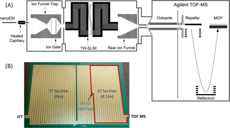
(A) Schematic of the experimental setup used in this work. (B) Photo of the bottom surface of TW SLIM module used for the present CRIMP studies showing location of the two distinct sections and the TT–ST interface, as detailed in the Experimental Section.
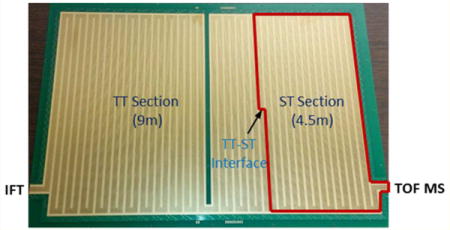
The TW SLIM module enabling ion compression was designed based upon a 13 m long serpentine path SLIM module described previously26 and used the same rf, TW, guard electrode arrangements, and spacing between two surfaces (2.75 mm). The serpentine path utilized 6 rf strips (0.43 mm wide) and 5 TW electrode arrays (0.43 mm wide and 1.03 mm long); the gaps between electrodes were 0.13 mm. Guard electrodes (3.0 mm wide) were used to laterally confine ions along the ion path (Figure 1B). A power supply (GAA Custom Engineering, LLC, Benton City, WA) provided an rf waveform of 822 kHz, 180° out-of-phase to adjacent rf electrodes to create pseudopotentials preventing ion loss to surfaces. The serpentine ion path was divided into two separately controllable sections (Figure 1B); one 9 m long section in which normal TW (TW1) is applied and most of the separation occurs (and we will refer to the “TT section”), and a 4.5 m long section in which an intermittent/stuttering TW (TW2) could be applied and that could also be switched to normal TW operation (which we will refer to as the “ST section”). The TW potentials were applied to subsets of eight electrodes in each of the five TW arrays and repeated across the entire ion path. The voltage profile on each of the eight electrode sets used four contiguous electrodes at a higher TW amplitude (H) followed by four electrodes at the lower amplitude (L), ground potential in this work (i.e., HHHHLLLL).19 This TW profile is then stepped one electrode forward at a time, to create the TW that propagates throughout the entire SLIM module (i.e., LHHHHLLL, followed by LLHHHHLL⋯, etc.). To enable CRIMP,30 the stuttering traps voltage profile is applied to the ST region where the TW potentials applied use the same timing clock and are synchronized with the first TT section (Figure S-1). Consequently, the ion compression occurs or ions are accumulated as ions are either rebinned (by the stuttering wave) or effectively blocked (by the halted TW voltage profile) at the TT–ST interface.
Ions exit the TW SLIM module into a 15 cm long “rear” ion funnel (820 kHz and ∼120 Vpp) having a 6 V/cm dc gradient that focused ions through a conductance limiting orifice (2.5 mm i.d.) into the differentially pumped region (0.34 Torr) containing a short rf-only quadrupole (1 MHz and ∼130 Vpp) and where ion currents could also be measured as an alternative to transfer to the TOF MS. Ion currents were amplified using a fast current inverting amplifier (Model 428, Keithley Instrument, Inc., Cleveland, OH), and data were recorded using a TDS-784C digital oscilloscope (Tektronix, Richardson, TX). The TOF-MS was equipped with a 1.5 m flight tube (6224, Agilent Technologies, Santa Clara, CA). The signal from the TOF detector was routed into U1084A 8-bit ADC digitizer (Keysight Technologies, Santa Rosa, CA) and processed using in-house control software.
Agilent low-concentration ESI tuning mix (Agilent, Santa Clara, CA) was directly infused for characterizing the TW SLIM module. An equimolar 1 μM 9 peptide mix (bradykinin acetate salt, kemptide acetate salt, angiotensin I human acetate salt hydrate, angiotensin II human, neurotensin, renin substrate tetradecapeptide porcine, substance P acetate salt hydrate, melittin from honey bee venom, and fibrinopeptide A human) (Sigma-Aldrich, St. Louis, MO) prepared in 50% H2O/50% methanol (v/v) and 0.1% formic acid (v/v) and serial dilutions Were used.
RESULTS AND DISCUSSION
In this work we used CRIMP to replace the external ion trapping/accumulation (in the IFT in previous SLIM reports) with subsequent peak compression in SLIM to enable accumulation and analyses of a large number of ions. This not only simplifies the instrumental design but also provides greatly enlarged charge capacities and enables subsequent peak compression.30 These new approaches provide the basis for both higher sensitivity and higher resolution IM separations in multipass SLIM SUPER IM devices.
CRIMP peak compression and its utility in IM separations have been previously reported30 and entail repetitively taking ions distributed over multiple TW bins in the TT section and depositing them into one TW bin at the start of the ST section. CRIMP uses a conventional TW in the TT region in conjunction with a stuttering (or intermittently applied) TW in the ST region. A simplified illustration of CRIMP compression is shown in Figure 2. The IM peak/distribution in Figure 2 left top panel shows ions “quantized” into packets in a set of sequential TW bins (i.e., the IM peak spans six TW bins in TT section before compression). In this simplified view we ignore ions in the process of being passed by a TW (i.e., falling back into a previous TW bin). CRIMP compression occurs as ions from two TW bins in the TT region are deposited into a single TW bin in the ST region (Figure 2 right panel), as discussed in detail previously.30 A compression ratio (CR) of 2 results in a reduction in the number of TW bins in the ST region to which ions are redistributed by a factor of 2 (Figure 2 bottom panel). After the desired region of the ion distribution (e.g., a large band of ions or an entire IM separation) is compressed, a normal TW is resumed in the ST region, effectively “locking in” the physical compression and providing temporal compression of the distribution (e.g., IM peaks).30 The essentially quantized nature of ion distributions due to the low potential troughs of the traveling waves allows for integer CR and corresponds to the number of TW bins in the TT region that are merged to a single TW bin in the ST region and repeated across the selected ion distribution during the stationary time of the TW in the ST region. Thus, CR is defined as
| (1) |
Figure 2.
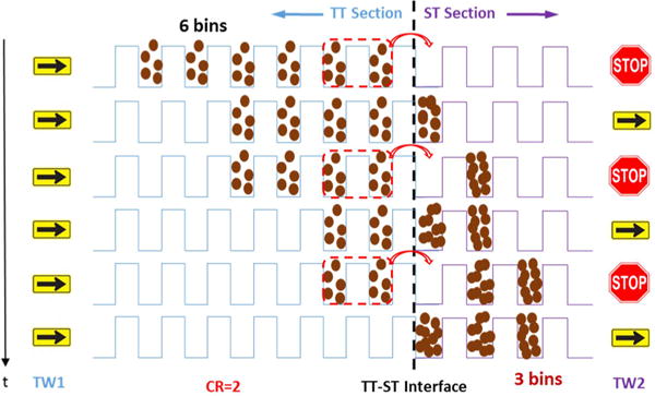
Simplified illustration of the peak compression process for an IM peak occupying six TW bins in the TT section which is compressed into three TW bins in the ST section using CR = 2. Importantly, the TW in the ST section must be switched to normal TW (i.e., same as in the TT section) for the compression to be “locked-in”.
When CR = 1 the TWs in TT and ST regions are identical to the conventional TW resulting in a normal mode of IM separation. When CRIMP is applied (CR ≥ 2), the TW bins in the ST region move at the same frequency (i.e., speed) as TW bins in the TT region but do so intermittently (i.e., stuttering mode).
Therefore, at the TT–ST interface ions being separated by IM in the TT region collapse into tighter packets in the ST region; an IM peak spanning a number of TW bins in the TT region is repopulated into fewer TW bins in the ST region, resulting in spatial compression. The spatially compressed ion population (e.g., encompassing an entire separation or set of IM peaks) is then switched to the normal TW condition (that of the TT region) to “lock in” the compression (Figures 2 and S-1). We have previously shown CRIMP compression provides increased IM peak intensities, reduced peak widths, improved resolution, and improved S/N ratios with MS detection.30
In this work we use CRIMP to modulate either bands or streams of continuously introduced ions. Figure 3A shows ion currents measured at the quadrupole as a function of the CR for a 100 ms wide band of ions injected from the IFT to the SLIM TT region using CRs from 1 (no compression) to 50. The detected width of the band (fwhm) observed for CR = 1 is consistent with the ion injection period (Table 1). As the CR was increased from 2 to 10, the peak widths were observed to narrow to ∼100/CR ms, consistent with expectations (Table 1). The peak heights also increased with CR (Figure 3A), while the peak area (proportional to the number of charges) remained constant (Figure 3B), indicating essentially lossless performance. Thus, for CR < 10 nearly ideal performance (R2 = 0.99) was observed with CRIMP. However, for CR > 10 the overall number of charges detected decreased (Figure 3B), and the observed peak widths were also greater than expected (Figure 3C and Table 1). We attribute these observations of both modest ion losses and broader ion bands due to “over-compression” of the large initial ion population introduced from the IFT (∼24 million charges) causing excessive space charge.
Figure 3.
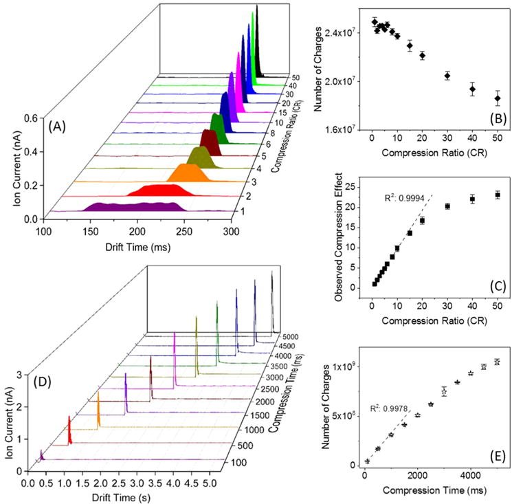
Compressing an ion band: (A) Ion currents measured at the quadrupole following the SLIM at different CRs for 100 ms long ion band injection events. (B) Number of charges measured at the quadrupole as a function of CR. (C) The observed compression vs selected CR. Compressing a continuous ion beam: (D) Ion current at the quadrupole after the SLIM for continuously introduced ions from ESI of the low concentration Agilent tuning mix solution for various compression times and CR = 200. The increased baseline following the detected ion band is due to the resumption of the continuously introduced ions. (E) Number of charges detected at the quadrupole as calculated from the detected ion pulse areas.
Table 1.
Experimentally Yielded and Theoretically Calculated Compressed Peak Width (FWHM) of the Ion Current Bands (Peaks) at Different CRs (Figure 3C)
| compression ratio (CR) | compressed peak width (fwhm)
|
|
|---|---|---|
| experimental | theoretical | |
| 1 | 101.59 | 100.00 |
| 2 | 50.85 | 50.00 |
| 3 | 34.63 | 33.33 |
| 4 | 26.26 | 25.00 |
| 5 | 21.22 | 20.00 |
| 6 | 17.06 | 16.67 |
| 8 | 13.19 | 12.50 |
| 10 | 10.41 | 10.00 |
| 15 | 7.49 | 6.67 |
| 20 | 6.07 | 5.00 |
| 30 | 5.01 | 3.33 |
| 40 | 4.61 | 2.50 |
| 50 | 4.40 | 2.00 |
We explored the use of continuous introduction of ions from the IFT and a very large CR (e.g., 200) applied for different periods of time (up to 5 s). Figure 3D shows the compressed ion current pulses measured at the quadrupole as a function of compression time applied for the continuously introduced ion population. For a shorter compression period (<1 s), the detected peak amplitude increased nearly linearly with compression time. Figure 3E shows the number of charges increased linearly to ∼1.5 × 10⁸ and reached ∼1 × 10⁹ at 5 s. As the compression time increased (e.g., at CR 200), greater numbers of incoming ions encounter excessively filled ST traps, leading to space charge driven ion redistribution, and with both ion losses and high m/z ion discrimination observed for very long compression times (>4.5 s).
Thus, it is highly desirable to avoid the detrimental effects of ion activation, loss, and mass discrimination due to excessive space charge during CRIMP. To avoid these negative effects, we have initially explored the use of space charge to alternatively cause ion redistribution into adjacent TW bins. For this purpose we use low TW amplitudes selected to allow facile space charge related driven ion redistribution, avoiding significant ion losses and ion activation. Thus, we provide an approach for the accumulation of very large ion populations in the SLIM path length needed. An initial implementation of this approach is described below.
Our initial work has shown CRIMP can be used to both temporally and spatially reduce the width of a large ion pulse, an IM separation, or essentially any ion distribution in SLIM.30 However, it also has utility for accumulating extremely large number of ions for IM separations in SLIM using a portion of its long path length as an enormous ion accumulation region. In this work we used the 9 m long TT region for ion accumulation by preventing ions from entering the ST region using a stationary waveform (i.e., CR = ∞) in the ST region, and thus blocking ions at the TT–ST interface. Ions are introduced continuously from the source and transmitted through the TT region using a gentle (low-amplitude) TW, selected as described above. Ions arriving at the TT–ST interface experience a potential wall and begin accumulate in the TT section near the interface, with space charge causing ions arriving later to “queue up” behind the already accumulated ions with the requirement that the TW speed and amplitude selected are sufficiently gentle to allow this space charge related ion reshuffling. To enable gentle conditions, a TW amplitude (H) of 7 V was used in the TT section in conjunction with a HLLLLLLL TW sequence, allowing ions to easily “roll over” waves into adjacent TW bins. Thus, as ions are accumulated, the TW in the TT region pushing ions toward the TT–ST interface wall is sufficiently gentle to allow ions to roll back if and when there was a sufficient repulsive “push” due to space charge. We again emphasize that without the use of such gentle TW conditions, ion activation and/or loss will occur due to excessive space charge (e.g., ions expanding into higher rf field regions).
After ion accumulation, the TW in the ST region is switched to the normal TW mode, and the accumulated ions are released from the TT region. Figure 4A shows the ion current recorded after the SLIM module (measured at the quadrupole) when accumulating ions for 10 s. Six broad peaks were observed which we attribute to partial separation for the major species in the mixture. The area under the curve in Figure 4A gives the total number of charges accumulated. Longer accumulation times allow greater numbers of charges to be accumulated. Figure 4B shows the number of charges accumulated, calculated based upon the detected ion currents at the quadrupole rods after rear ion funnel. The number of charges detected increased as a function of accumulation time over the range of 0.1–80 s, reaching ∼5 × 10⁹ for an accumulation time of 40 s, and plateauing at ∼80 s. The linear range for quantitative utility extended to ∼1 × 10⁹ charges and an accumulation time of ∼3 s in the present work (Figure 4B). The ion accumulation efficiency31 was estimated to be ∼95% in linear range (<3 s) and ∼20% at 80 s (where the TT section is clearly “overfilled”). These trapped ion populations are ∼16-fold greater than obtained using the recently developed TW SLIM “flat funnel”31 and exceed by more than 2 orders of magnitude of the charge capacity of any other previously reported ion trap used with either IM or MS.29
Figure 4.
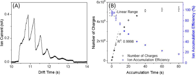
(A) Ion current measured at the quadrupole rods after the SLIM module using an accumulation time of 10 s. (B) Number of charges detected at the quadrupole as calculated from the detected ion band areas, and the resulting ion accumulation efficiencies.
The SLIM parameters that impact the ion-trapping process, including TW speed and amplitude during ion filling and ion release, TW sequence, and guard bias, were evaluated systematically based upon the number of charges at a specific accumulation time (e.g., 5 s), as shown in Supporting Information Figure S-2. TW speed, guard bias, and TW sequences from HLLLLLLL to HHHHHHLL have negligible effect on ion accumulation and release. However, a TW sequence of HHHHHHHL was ineffective for ion filling and ejection (Figure S-2A, B, and C). Low TW amplitudes in the TT region (e.g., < 15 V) facilitate ion filling (Figure S-2D) but (e.g., <25 V) are ineffective for ion release. High TW amplitudes (e.g., >40 V) reduced ion transmission efficiencies (i.e., caused ion losses) attributed to their use in conjunction with the relatively low 15 V guard bias applied (as shown in Figure S-2E; such losses can be eliminated by using a higher guard bias). High rf amplitudes provided somewhat greater ion confinement and modest increases in maximum trapped ion populations (Figure S-2F). Overall, we find the SLIM module and the use of suitable TT and ST potentials enables billions of ions to be accumulated in an efficient fashion and ejected, and the basis for greatly increasing ion populations used for IM separations.
To be of broad utility for IM separations, ion accumulation should ideally result in higher S/N ratios and not be accompanied by ion activation (e.g., significant ion heating or dissociation). To initially investigate the possibility of ion activation, we accumulated ions in the TT section from ESI of a 0.1 μM nine peptides mixture for 1 s. Figure 5A shows the mass spectrum obtained in the continuous/transmission mode, and Figure 5B shows the mass spectrum obtained in the accumulation/trapping mode. Significantly greater intensities were observed for protonated parent ions in the accumulation mode, with no evident fragmentation or change in the m/z ion range. The improved signal-to-noise ratios (S/N) are primarily attributed to the increased number of ions transported to the TOF MS due to the ion accumulation step. However, we also note that the “chemical noise” with the accumulation mode was also significantly reduced. We attribute this observation to the additioinal desolvation of electrospray-related species during the ion accumulation, a phenomenon we have previously noted after accumulation and trapping of ions from electrospray in the IFT29 and which can significantly improve the instrumental limits-of-detection (LOD). Figures 5C and D show portions of mass spectra obtained using a 1 pM solution of melittin in both continuous (i.e., no accumulation) and trapping (i.e., accumulation) modes (a corresponding mass spectrum obtained for 50% methanol in water is shown in the Supporting Information, Figure S-3). The solution was infused at a flow rate of 60 nL/min, and both mass spectra were obtained over a 50 s time period, corresponding to 50 zmol of analyte introduced. The mass spectrum in Figure 5C shows pronounced chemical noise, while Figure 5D shows this to be dramatically reduced, resulting in ∼eightfold gain in S/N. The linear dynamic range for ion accumulation was studied using a melittin solution at concentrations ranging from 1 pM to 10 nM. Figure 5E shows the intensity (summed 50 times) of the melittin [M + 4H]4+ monoisotopic peak as a function of concentration, where the greater ion accumulation increases the linear dynamic range, ∼4 orders of magnitude in this case. The nonlinearity at concentrations >10 nM (Supporting Information, Figure S-4) is due to the saturation of the MS detector or analog-to-digital converter. Thus, CRIMP in SLIM can enable the accumulation of extremely large ion populations (>109) without activation based upon the application of suitable combinations of TT and ST voltages.
Figure 5.
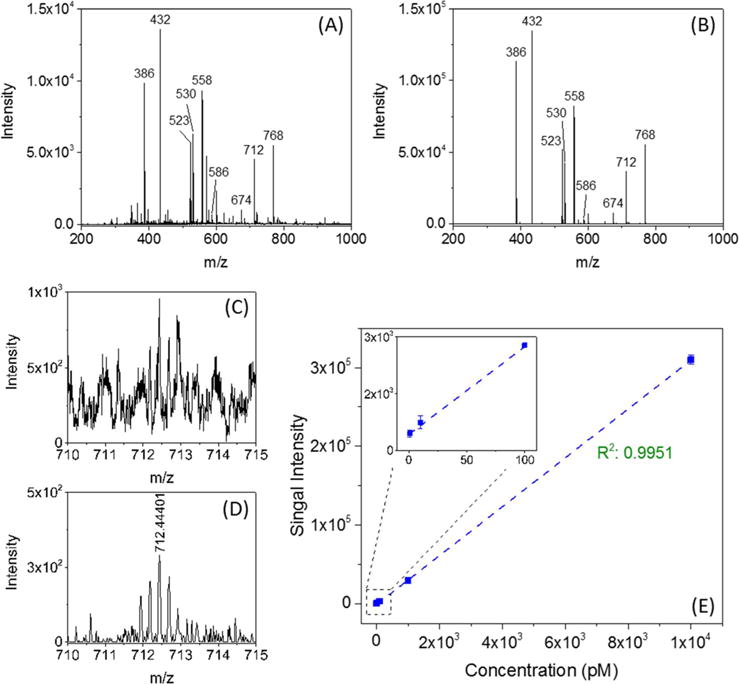
Mass spectra for ESI of nine peptides obtained (A) in continuous mode, and (B) in accumulation mode at an accumulation time of 1 s, indicating little or no ion activation occurs during CRIMP accumulation. (C) [M + 4H]4+ region from a 1 pM of melittin solution in the continuous mode and (D) in trapping mode. (E) Monoisotopic [M + 4H]4+ peak intensity of melittin as a function of concentration for an accumulation time of 1 s. The inset shows the signal intensity observed over the concentration range of 1–100 pM and infused at 60 nL/min. In both continuous and trapping modes the total TOF MS acquisition time was 50 s.
CONCLUSIONS
In this work, we have developed a TW SLIM module in conjunction with CRIMP to enable accumulation and compression of large ion populations over extended periods and provide greatly increased charge capacities. The extent of the ion population spatial compression is only limited by the onset of space charge effects, where excessively large CRs can lead to ion losses and other compression artifacts (e.g., reduction of the compression effects, ion activation). The accumulation is achieved by applying a stationary TW in the ST region for ion filling in the TT region and then resuming to normal TW operation for ion ejection. The number of charges accumulated (∼5 × 10⁹) in the 9 m region of the present SLIM module is more than 2 orders of magnitude greater than the previously reported charge capacity for the IFT, and much greater populations appear to be feasible.
The use of CRIMP within TW SLIM enables greatly expanded ion accumulation and injection without the use of grids, and the basis for doing this in conjunction with ion compression in a manner that is compatible with subsequent IM separations. We have shown that the present implementation of CRIMP for ion accumulation significantly enhances the limit of detection for peptides and provides an ∼100-fold increase in sensitivity compared to that achieved using an IFT. More importantly, the integration of the ion accumulation and compression processes with multipass TW SLIM SUPER IM27 has the potential to achieve ultrahigh resolution separations in conjunction with ultrahigh sensitivity. We anticipate that the SLIM CRIMP and SUPER IM-MS capabilities will have broad applicability.
Supplementary Material
Acknowledgments
Portions of this research were supported by grants from the National Institute of General Medical Sciences (P41 GM103493), the Laboratory Directed Research and Development Program at Pacific Northwest National Laboratory, and the U.S. Department of Energy Office of Biological and Environmental Research Genome Sciences Program under the Pan-omics Program. This work was performed at the W. R. Wiley Environmental Molecular Sciences Laboratory (EMSL), a DOE national scientific user facility at the Pacific Northwest National Laboratory (PNNL). PNNL is operated by Battelle for the DOE under contract DE-AC05-76RL0 1830.
Footnotes
Supporting Information
The Supporting Information is available free of charge on the ACS Publications website at DOI: 10.1021/acs.analchem.7b00189.
Figures S1−S4 (PDF)
ORCID
Xueyun Zheng: 0000-0001-9782-4521
Erin S. Baker: 0000-0001-5246-2213
Yehia M. Ibrahim: 0000-0001-6085-193X
Richard D. Smith: 0000-0002-2381-2349
Notes
The authors declare no competing financial interest.
References
- 1.Kanu AB, Dwivedi P, Tam M, Matz L, Hill HH. J Mass Spectrom. 2008;43(1):1. doi: 10.1002/jms.1383. [DOI] [PubMed] [Google Scholar]
- 2.McLean JA, Ruotolo BT, Gillig KJ, Russell DH. Int J Mass Spectrom. 2005;240(3):301. [Google Scholar]
- 3.Clowers BH, Ibrahim YM, Prior DC, Danielson WF, Belov ME, Smith RD. Anal Chem. 2008;80(3):612. doi: 10.1021/ac701648p. [DOI] [PMC free article] [PubMed] [Google Scholar]
- 4.Li HL, Bendiak B, Siems WF, Gang DR, Hill HH. Rapid Commun Mass Spectrom. 2013;27(23):2699. doi: 10.1002/rcm.6720. [DOI] [PMC free article] [PubMed] [Google Scholar]
- 5.Paglia G, Williams JP, Menikarachchi L, Thompson JW, Tyldesley-Worster R, Halldorsson S, Rolfsson O, Moseley A, Grant D, Langridge J, Palsson BO, Astarita G. Anal Chem. 2014;86(8):3985. doi: 10.1021/ac500405x. [DOI] [PMC free article] [PubMed] [Google Scholar]
- 6.Jurneczko E, Cruickshank F, Porrini M, Nikolova P, Campuzano IDG, Morris M, Barran PE. Biochem Soc Trans. 2012;40:1021. doi: 10.1042/BST20120125. [DOI] [PubMed] [Google Scholar]
- 7.Knapman TW, Valette NM, Warriner SL, Ashcroft AE. Curr Anal Chem. 2013;9(2):181. doi: 10.2174/1573411011309020004. [DOI] [PMC free article] [PubMed] [Google Scholar]
- 8.Hinneburg H, Hofmann J, Struwe WB, Thader A, Altmann F, Silva DV, Seeberger PH, Pagel K, Kolarich D. Chem Commun. 2016;52(23):4381. doi: 10.1039/c6cc01114d. [DOI] [PubMed] [Google Scholar]
- 9.Marcoux J, Champion T, Colas O, Wagner-Rousset E, Corvaia N, Van Dorsselaer A, Beck A, Cianferani S. Protein Sci. 2015;24(8):1210. doi: 10.1002/pro.2666. [DOI] [PMC free article] [PubMed] [Google Scholar]
- 10.Cui WD, Zhang H, Blankenship RE, Gross ML. Protein Sci. 2015;24(8):1325. doi: 10.1002/pro.2712. [DOI] [PMC free article] [PubMed] [Google Scholar]
- 11.Lanucara F, Holman SW, Gray CJ, Eyers CE. Nat Chem. 2014;6(4):281. doi: 10.1038/nchem.1889. [DOI] [PubMed] [Google Scholar]
- 12.Giles K, Williams JP, Campuzano I. Rapid Commun Mass Spectrom. 2011;25(11):1559. doi: 10.1002/rcm.5013. [DOI] [PubMed] [Google Scholar]
- 13.Silveira JA, Ridgeway ME, Park MA. Anal Chem. 2014;86(12):5624. doi: 10.1021/ac501261h. [DOI] [PubMed] [Google Scholar]
- 14.Shvartsburg AA, Seim TA, Danielson WF, Norheim R, Moore RJ, Anderson GA, Smith RD. J Am Soc Mass Spectrom. 2013;24(1):109. doi: 10.1007/s13361-012-0517-5. [DOI] [PMC free article] [PubMed] [Google Scholar]
- 15.Chen TC, Ibrahim YM, Webb IK, Garimella SVB, Zhang X, Hamid AM, Deng LL, Karnesky WE, Prost SA, Sandoval JA, Norheim RV, Anderson GA, Tolmachev AV, Baker ES, Smith RD. Anal Chem. 2016;88(3):1728. doi: 10.1021/acs.analchem.5b03910. [DOI] [PMC free article] [PubMed] [Google Scholar]
- 16.Garimella SVB, Ibrahim YM, Webb IK, Ipsen AB, Chen TC, Tolmachev AV, Baker ES, Anderson GA, Smith RD. Analyst. 2015;14(20):6845. doi: 10.1039/c5an00844a. [DOI] [PMC free article] [PubMed] [Google Scholar]
- 17.Garimella SVB, Ibrahim YM, Webb IK, Tolmachev AV, Zhang XY, Prost SA, Anderson GA, Smith RD. J Am Soc Mass Spectrom. 2014;25(11):1890. doi: 10.1007/s13361-014-0976-y. [DOI] [PMC free article] [PubMed] [Google Scholar]
- 18.Hamid AM, Garimella SVB, Ibrahim YM, Deng LL, Zheng XY, Webb IK, Anderson GA, Prost SA, Norheim RV, Tolmachev AV, Baker ES, Smith RD. Anal Chem. 2016;88(18):8949. doi: 10.1021/acs.analchem.6b01914. [DOI] [PMC free article] [PubMed] [Google Scholar]
- 19.Hamid AM, Ibrahim YM, Garimella SVB, Webb IK, Deng LL, Chen TC, Anderson GA, Prost SA, Norheim RV, Tolmachev AV, Smith RD. Anal Chem. 2015;87(22):11301. doi: 10.1021/acs.analchem.5b02481. [DOI] [PMC free article] [PubMed] [Google Scholar]
- 20.Tolmachev AV, Webb IK, Ibrahim YM, Garimella SVB, Zhang XY, Anderson GA, Smith RD. Anal Chem. 2014;86(18):9162. doi: 10.1021/ac502054p. [DOI] [PMC free article] [PubMed] [Google Scholar]
- 21.Webb IK, Garimella SVB, Norheim RV, Baker ES, Ibrahim YM, Smith RD. J Am Soc Mass Spectrom. 2016;27(7):1285. doi: 10.1007/s13361-016-1397-x. [DOI] [PMC free article] [PubMed] [Google Scholar]
- 22.Webb IK, Garimella SVB, Tolmachev AV, Chen TC, Zhang XY, Cox JT, Norheim RV, Prost SA, LaMarche B, Anderson GA, Ibrahim YM, Smith RD. Anal Chem. 2014;86(19):9632. doi: 10.1021/ac502139e. [DOI] [PMC free article] [PubMed] [Google Scholar]
- 23.Webb IK, Garimella SVB, Tolmachev AV, Chen TC, Zhang XY, Norheim RV, Prost SA, LaMarche B, Anderson GA, Ibrahim YM, Smith RD. Anal Chem. 2014;86(18):9169. doi: 10.1021/ac502055e. [DOI] [PMC free article] [PubMed] [Google Scholar]
- 24.Zhang XY, Garimella SVB, Prost SA, Webb IK, Chen TC, Tang KQ, Tolmachev AV, Norheim RV, Baker ES, Anderson GA, Ibrahim YM, Smith RD. Anal Chem. 2015;87(12):6010. doi: 10.1021/acs.analchem.5b00214. [DOI] [PMC free article] [PubMed] [Google Scholar]
- 25.Deng LL, Ibrahim YM, Baker ES, Aly NA, Hamid AM, Zhang X, Zheng XY, Garimella SVB, Webb IK, Prost SA, Sandoval JA, Norheim RV, Anderson GA, Tolmachev AV, Smith RD. ChemistrySelect. 2016;1:2396. doi: 10.1002/slct.201600460. [DOI] [PMC free article] [PubMed] [Google Scholar]
- 26.Deng LL, Ibrahim YM, Hamid AM, Garimella SVB, Webb IK, Zheng XY, Prost SA, Sandoval JA, Norheim RV, Anderson GA, Tolmachev AV, Baker ES, Smith RD. Anal Chem. 2016;88(18):8957. doi: 10.1021/acs.analchem.6b01915. [DOI] [PMC free article] [PubMed] [Google Scholar]
- 27.Deng LL, Webb IK, Garimella SVB, Hamid AM, Zheng XY, Norheim RV, Prost SA, Anderson GA, Sandoval JA, Baker ES, Ibrahim YM, Smith DR. Anal Chem. 2017;89:4628. doi: 10.1021/acs.analchem.7b00185. [DOI] [PMC free article] [PubMed] [Google Scholar]
- 28.Garimella SVB, Ibrahim YM, Tang KQ, Webb IK, Baker ES, Tolmachev AV, Chen TC, Anderson GA, Smith RD. J Am Soc Mass Spectrom. 2016;27(6):1128. doi: 10.1007/s13361-016-1371-7. [DOI] [PMC free article] [PubMed] [Google Scholar]
- 29.Ibrahim Y, Belov ME, Tolmachev AV, Prior DC, Smith RD. Anal Chem. 2007;79(20):7845. doi: 10.1021/ac071091m. [DOI] [PMC free article] [PubMed] [Google Scholar]
- 30.Garimella SVB, Hamid AM, Deng L, Ibrahim YM, Webb IK, Baker ES, Prost SA, Norheim RV, Anderson GA, Smith RD. Anal Chem. 2016;88(23):11877. doi: 10.1021/acs.analchem.6b03660. [DOI] [PMC free article] [PubMed] [Google Scholar]
- 31.Deng LL, Ibrahim YM, Garimella SVB, Webb IK, Hamid AM, Norheim RV, Prost SA, Sandoval JA, Baker ES, Smith RD. Anal Chem. 2016;88(20):10143. doi: 10.1021/acs.analchem.6b02678. [DOI] [PMC free article] [PubMed] [Google Scholar]
Associated Data
This section collects any data citations, data availability statements, or supplementary materials included in this article.


