Significance
Plants are sessile organisms without nerves. As such, they have developed specific mechanisms to carry information rapidly throughout their body in response to mechanical stimuli. Recently, it has been suggested that the first stage of this long-distance signaling could be the propagation of hydraulic signals induced by the mechanical deformation of the plant tissue (bending), but the physical origin of this hydromechanical coupling remains a conundrum. Here, we address this issue by combining experiments on natural tree branches and soft biomimetic beams with modeling. We reveal a generic nonlinear mechanism responsible for the generation of hydraulic pulses induced by bending in poroelastic branches. Our study gives a physical basis for long-distance communication in plants based on fast hydraulic signals.
Keywords: plant biomechanics, biomimetism, long-distance signaling, poroelasticity, nonlinear beams
Abstract
Plants constantly undergo external mechanical loads such as wind or touch and respond to these stimuli by acclimating their growth processes. A fascinating feature of this mechanical-induced growth response is that it can occur rapidly and at long distance from the initial site of stimulation, suggesting the existence of a fast signal that propagates across the whole plant. The nature and origin of the signal is still not understood, but it has been recently suggested that it could be purely mechanical and originate from the coupling between the local deformation of the tissues (bending) and the water pressure in the plant vascular system. Here, we address the physical origin of this hydromechanical coupling using a biomimetic strategy. We designed soft artificial branches perforated with longitudinal liquid-filled channels that mimic the basic features of natural stems and branches. In response to bending, a strong overpressure is generated in the channels that varies quadratically with the bending curvature. A model based on a mechanism analogous to the ovalization of hollow tubes enables us to predict quantitatively this nonlinear poroelastic response and identify the key physical parameters that control the generation of the pressure pulse. Further experiments conducted on natural tree branches reveal the same phenomenology. Once rescaled by the model prediction, both the biomimetic and natural branches fall on the same master curve, enlightening the universality of our poroelastic mechanism for the generation of hydraulic signals in plants.
Since Darwin and Knight (1, 2), scientists have known that plants are able to perceive external mechanical perturbation and respond to these stimuli by modifying their growth, a process called thigmomorphogenesis (3–6). In response to mechanical stress, plants tend to decrease their elongation growth and, for plants having secondary growth like trees, increase the diameter of their organs. Over the past decades, reports have refined our understanding of thigmomorphogenesis at the biomechanical, physiological, and molecular levels (4, 7–12). A remarkable feature of this mechanically induced response is that it can be local and also nonlocal. When a shoot is bent, a sudden arrest of the elongation growth is observed far away from the perturbed area (13) within minutes (8). These experiments demonstrate that plants can carry mechanosensing information over a long distance (from centimeters to meters) very rapidly throughout the whole organ. Among the different hypotheses for this long-distance signaling [hormones transport and electrical signals (14–16)], it has long been argued that hydraulic pulses could provide a unique way for rapid communication in plants, thanks to their highly connected hydraulic network that brings water from the roots to the leaves (16–18). Propagating hydraulic waves were first mentioned by Ricca in the 1920s during his study of the sensitive plant Mimosa pudica (19) and later observed in different organisms in response to wounding stress, often in association with electrical waves of depolarization (20–22). Recently, Lopez et al. (23) observed that bending the stem of a whole living tree or an isolated branch segment generates a sudden overpressure that propagates rapidly in the plant vascular system. This hydraulic signal induced by a nonwounding elastic stress appears as a promising candidate for the rapid communication of the thigmomorphogenetic response. However, the physical mechanisms responsible for its generation and the parameters that govern its properties remain poorly understood. In mechanics, the hydraulic response of a porous material saturated with water, like a branch or a stem, is described by the poroelastic theory (24, 25). In this framework, the bending of a branch is expected to induce local water expulsion/suction in response to the longitudinal compression/tension strains of the plant tissues from both sides of the neutral surface of the branch. However, according to the linear beam theory, these local changes of volume should cancel each other out in average over the whole system. Therefore, it remains unclear how hydraulic signals could be generated in plants from such bending stress.
The objective of this study is to understand the origin of this hydromechanical coupling and the physical parameters that control the generation of hydraulic pulses induced by bending in plant tissues. To this end, we use a biomimetic approach (26–29) and study the hydraulic response to bending of soft artificial branches that mimic the basic structural and mechanical features of natural stems and branches. While previous theoretical and experimental works have studied the linear behavior of poroelastic beams (30–32), very few have investigated the large deformation regime of fluid-infiltrated media composed of cellular materials like wood or soft plant tissues (33). In this work, we demonstrate a generic nonlinear mechanism responsible for the generation of hydraulic pulses in both biomimetic and natural tree branches representative of wood diversity.
Results
Evidence of Hydraulic Pulses Induced by Bending in Soft Biomimetic Branches.
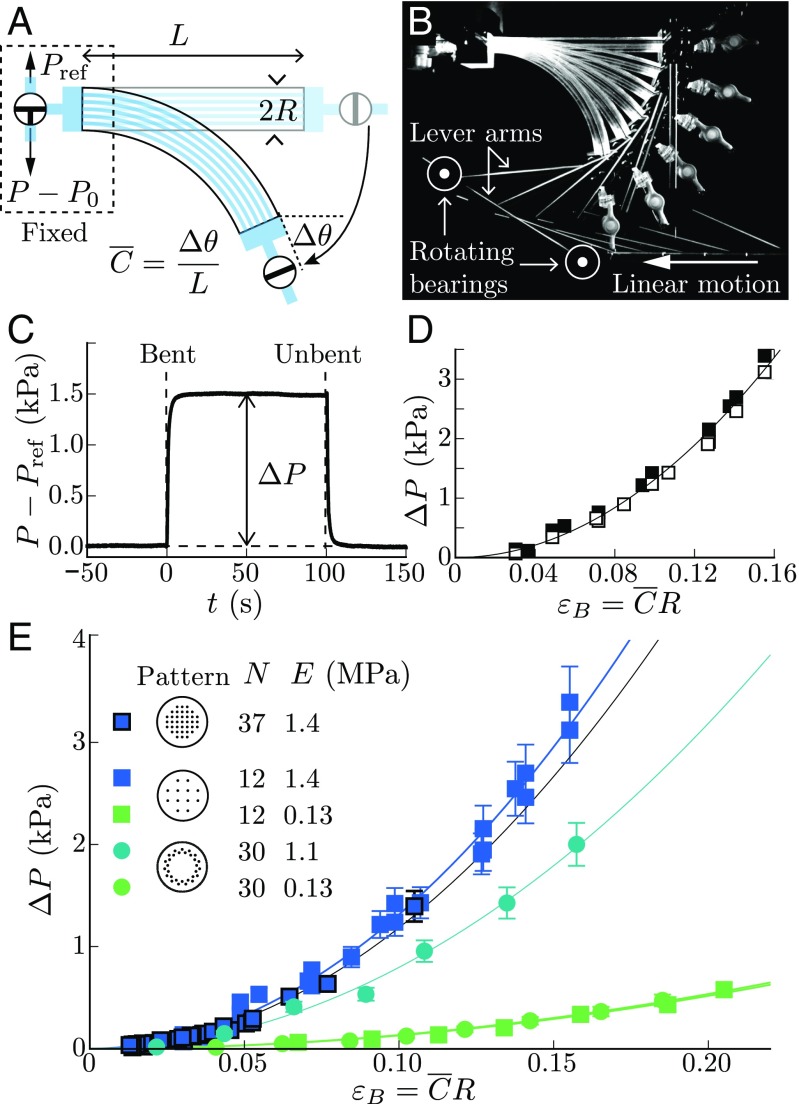
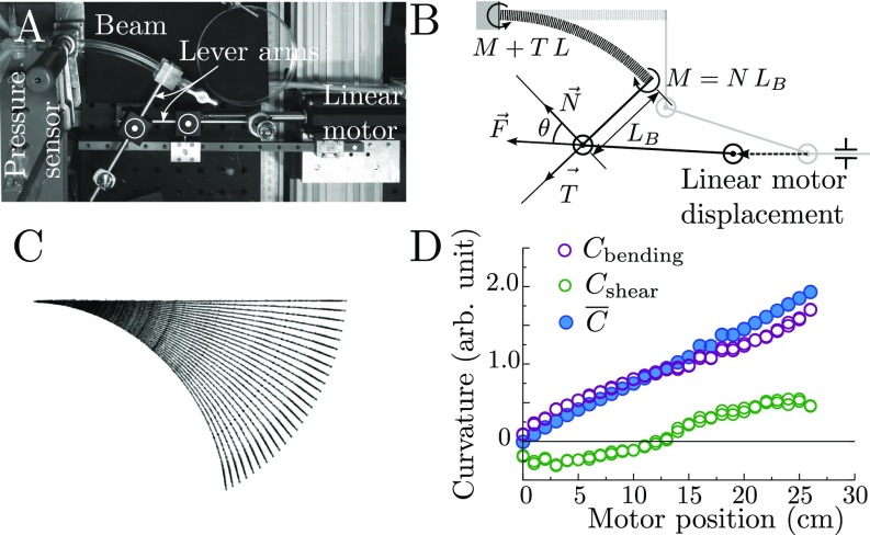
From a mechanical perspective, tree branches and stems can be viewed in first approximation as flexible elastic beams composed of microchannels that carry water longitudinally (34, 35) (Fig. 1A). To mimic these minimal ingredients, we use polydimethylsiloxane (PDMS)-based 3D molding techniques to design soft synthetic branches (Young modulus MPa, radius mm, length mm) perforated with parallel longitudinal microchannels (diameter m) with various channel numbers and array patterns (Fig. 1 B and C and Materials and Methods). The channels are filled with a nonvolatile liquid (silicone oil) and connected together to a pressure sensor at one extremity of the beam, while the other extremity is closed (Fig. 2A). To bend the branch, we design an original setup in which one extremity of the beam is fixed and the other is moved by using a system of pivoting arms connected to a linear displacement motor (Fig. 2B, Bending Setup for the Biomimetic Branches, and Fig. S1). This enables us to apply a uniform curvature on the soft beam, while minimizing compressional and shearing effects within the material. The bending strain is then defined as the maximal longitudinal strain in the beam: (36), where is the mean curvature measured by image analysis.
Fig. 1.
Natural vs. biomimetic tree branches. (A) X-ray microtomography of a Vitis vinifera branch (grape vine), showing the network of longitudinal conducting vessels (dark gray). (B) Sketch of the mold used to design the synthetic branch with the different channel patterns investigated (Top, square array, ; Middle, square array, ; Bottom, circular array, ): i, piano strings; ii, POM plate; iii, Plexiglas tube; iv, Plexiglas block. (C) Picture of the synthetic branch made of PDMS elastomer after removal from the mold (Materials and Methods).
Fig. 2.
Hydraulic pulse induced by bending in PDMS biomimetic branches. (A and B) Sketch (A) and picture (B) of the bending setup and pressure measurements, where is the variation of angle between the free extremity and the clamped extremity of the beam, the mean curvature of the beam, the beam radius, is the initial fluid-pressure in the channels, and is the fluid-pressure in the channels relative to the atmospheric pressure. (C) Pressure response to bending/unbending sequence in a closed system (square channel pattern, , MPa, ). (D) Steady overpressure vs. bending strain . Filled square, bent/unbent cycles with return to the straight state; open square, positive ramp of strain. (E) Overpressure vs. bending strain for various channel patterns, number of channels , and PDMS Young moduli . The solid lines in D and E are quadratic fits of the data.
Fig. S1.
(A) Top view of the bending setup, including a linear motor, lever arms, and rotating bearings. (B) Force balance on the bent beam. Once the displacement is imposed, the beam is subject to a force which creates a bending moment , a compression force , and a tangential force . (C) Beam’s profiles extracted by image analysis from top views during a sequence of motor displacements. Each profile is fitted by a law such that , where and are fitting parameters and is the coordinate along the beam. (D) Curvatures measured from the beam profiles as function of the displacement of the motor where .
A typical pressure response of the synthetic branch for a bending strain of order 10 is shown in Fig. 2C. Here, the beam is initially straight, and the internal fluid pressure in the channels is equal to the atmospheric pressure (no effect of the initial pressure is noticed as long as is small compared with the beam Young’s modulus ). In response to bending, a mean overpressure rises up inside the channels and reaches a steady value of the order of a few kilopascals. When the branch is brought back to its initial straight shape, the overpressure goes back to zero, showing the reversible nature of this hydraulic response. The striking observation is that the overpressure strongly increases with the bending strain, with a quadratic relationship that is independent of the bending protocol (Fig. 2D). This nonlinearity does not come from the intrinsic material properties, since the maximal strain in our case () is far below the linear elastic limit of the PDMS elastomer (). Experiments with beams of different Young’s modulus and channel geometries all exhibit the quadratic relationship between the pressure and the bending strain (Fig. 2E). The response appears independent of the channels’ number or distribution, but strongly increases with the beam’s rigidity. This confirms that the generation of these hydraulic pulses arises from a purely elastic phenomenon.
Physical Modeling: A Nonlinear Poroelastic Coupling.
Our biomimetic system therefore contains the relevant physical ingredients needed to reproduce the hydraulic pulse induced by bending recently reported in plant tissues (23). However, explaining the generation of this pulse is not straightforward. Classical linear beam theory tells us that the total volume of a symmetrical bent beam should remain constant, regardless of its elastic properties (36). This would predict a null pressure variation in a closed poroelastic beam with interconnected channels, in contradiction with observations.
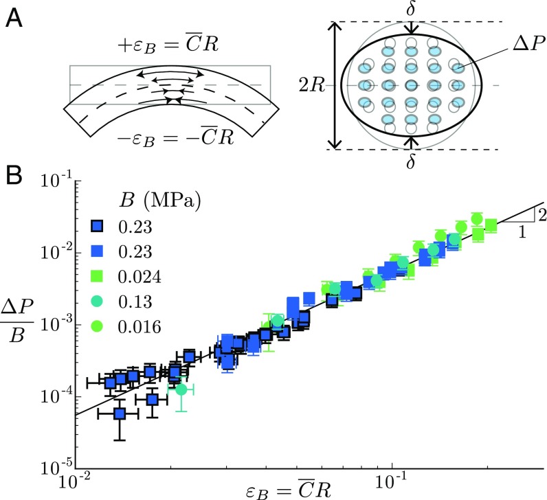
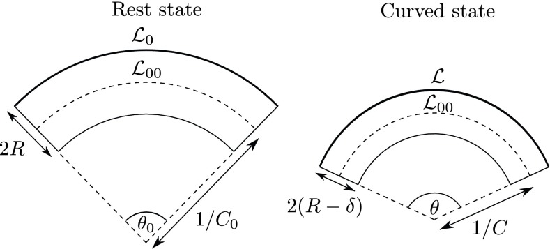
To solve this paradox, we propose a nonlinear mechanism analogous to the ovalization of thin elastic tubes (37). When an elastic beam is bent, the longitudinal elastic strain (extension or compression) increases linearly with the distance to the neutral surface (Fig. 3 A, Left). This induces a bending elastic energy per unit volume that varies quadratically with the radius of the beam, , where is the beam Young’s modulus and is the bending curvature, assumed uniform here (36). Therefore, a way for the system to lower the bending elastic energy is to squeeze its cross-section, hence decreasing the beam radius by a quantity in the transverse direction (Fig. 3 A, Right). The maximal bending strain then reduces to and the bending energy to . However, this transverse compression involves the cost of a positive compressive energy in the transverse direction . By minimizing the sum of the bending and compressive elastic energy, , the transverse compression is found to vary quadratically with the bending longitudinal strain: . For an elastic beam perforated with longitudinal channels, this compression is associated with a reduction of the channels’ volume , where is the total volume of the channels (38). If now the channels are filled with an incompressible liquid and closed, this reduction in volume is converted into a global rise of pore pressure , such that:
| [1] |
The coefficient , which relates the variation of liquid volume in the channels to the change of pore pressure, is an elastic bulk modulus known as the inverse of the specific storage coefficient in the poroelastic literature (39). Dimensionally, is proportional to the beam Young’s modulus and depends on the channels’ distribution and geometry. The dimensionless factor reads in the framework of this simple energy model, which assumes a uniform transverse compression (see Energy Model for Anisotropic Beams). A more elaborate model shows that the transverse compression is actually nonuniform and maximal at the neutral line (Materials and Methods, Eq. 2). As a result, is found to weakly depend on the channels’ distribution and varies between 0.56 and 0.59 for our biomimetic beams (Materials and Methods, Eq. 4).
Fig. 3.
Mechanism of hydraulic pulse generation and poroelastic modeling. (A) The nonlinear coupling between bending and transverse modes of deformation induces a transversal squeezing of the branch’s channels and thus an overpressure in the channels varying as , where is the elastic bulk modulus of the branch. (B) Overpressure normalized by the measured elastic bulk modulus as a function of the bending deformation for all biomimetic branches studied (same symbols as in Fig. 2E). The solid line gives the best quadratic fit of the data in log–log scale: ().
Our model therefore predicts that the bending of poroelastic beams filled with a liquid generates a global increase of the pressure that varies quadratically with the bending strain, as observed experimentally. To test Eq. 1, we independently measure the elastic bulk modulus of the biomimetic branches (Materials and Methods, Eq. 2). As predicted, data for various Young’s modulus and channel geometry all collapse into a single curve of slope 2 in log–log scale when overpressure is normalized by the bulk modulus (Fig. 3B). The prefactor found experimentally () agrees with the prediction of the model, showing the relevance of the nonlinear mechanism we propose for the generation of hydraulic pulses in the biomimetic porous branches (see Influence of the Bending Mode on the Pressure Response and Fig. S2 for additional comparison with the model in the case of a nonuniform curvature).
Fig. S2.
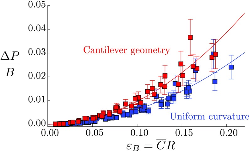
Pressure response to bending normalized by the elastic bulk modulus of the biomimetic branches as function of the bending deformation for a uniform curvature (blue symbols, quadratic fit ) and a linear variation of curvature (red symbols, quadratic fit ) (synthetic beams).
Experiments on Natural Woody Branches.
To check the validity of the model in the context of plants, we conduct experiments on natural tree branches and stems (Materials and Methods and Plant Materials). Three species representative of the wood anatomy diversity are studied: a gymnosperm species (P. sylvestris L.), whose conducting hydraulic network is made of tiny and short conduits (tracheids) regularly distributed; a ring porous angiosperm species (Quercus ilex L.), where the large conducting vessels are concentrated in the earlywood zone; and a diffuse porous angiosperm species (P. alba tremula L. clone 717-1B4), where the conducting vessels are homogeneously distributed in the annual ring structure (40). Freshly cut, well-hydrated branches are connected at one end to a pressure sensor and sealed at the other end to create a closed vascular system (Fig. 4A and Materials and Methods).
Fig. 4.
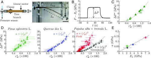
Hydraulic pulse induced by bending in natural tree branches. (A) Sketch of the experimental setup, where is the total branch length and the bent length. (Scale bar, 5 cm.) (B) Xylem water pressure measured at the fixed extremity of a pine branch (Pinus sylvestris L.) in response to a bent/unbent sequence. (C) Relationship between the overpressure and the bending strain for the same branch using two different bending protocols: incremental step displacement (filled symbols) and step displacement with return to the initial position after each bending (open symbols). Here, and , where and , with the mean curvature of the branch at rest (Extension of the Model to Beams with a Rest Curvature). The solid line is a quadratic fit of the data. (D) Overpressure vs. bending strain averaged over branches for different tree species and growing conditions (symbols) with quadratic fit (solid lines). Green: P. sylvestris L., , GPa, ; blue: Q. ilex L., , GPa, ; red: Populus alba tremula L. grown in field condition, , GPa, ; black: P. alba tremula L. grown in greenhouse conditions, , GPa, ). Each symbol corresponds to a running average over five data (seven data for poplar in field conditions) with an overlap of 50; error bars give the SD. (E) Coefficient of the quadratic fit as function of the longitudinal Young’s modulus (same color as in D). The coefficient is found proportional to (solid line: linear fit, ).
First, we observe that bending generates a large increase of the water pressure in the xylem, hence confirming the first observations of Lopez et al. (23) (Fig. 4B). The overpressure is independent of the bending rate or bending history (Fig. 4C), indicating a reversible response as in the case of the biomimetic branches. Second, for all branches and species studied, we again recover a quadratic relationship between the overpressure and the bending strain (Fig. 4D), once the pressure and the bending strain are properly defined to take into account dead-volume effects and the rest natural curvature of the branches (see Extension of the Model to Beams with a Rest Curvature, Fig. S3, and ref. 41 for the generalization of the model to naturally curved branches). The amplitude of the response for a given strain also strongly depends on the species or growing conditions, in addition to large intraspecific dispersions. By fitting the averaged data for each species and growing conditions by a quadratic law , we found a clear positive correlation between the amplitude factor and the longitudinal Young’s modulus of the branches (Fig. 4E). The case of P. alba tremula L. is especially instructive. Although all branches come from the same inbred line, the hydraulic pulse induced by bending is much higher in trees grown outside, which show much stiffer mechanical properties (red symbols in Fig. 4 D and E), than trees grown indoor, which show softer properties (black symbols in Fig. 4 D and E). This is a strong indication that elasticity, like in the biomimetic systems, controls the generation of the hydraulic pulse in natural branches.
Fig. S3.
Illustration of flattening of an initially curved beam induced by bending.
Comparison Between the Natural and Biomimetic Systems.
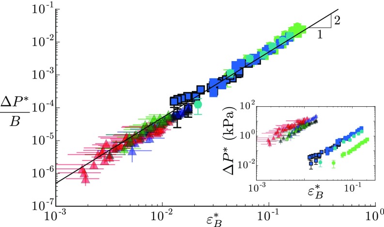
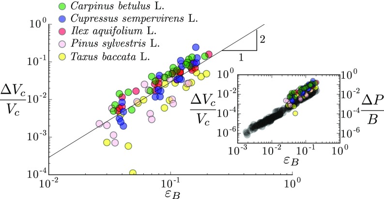
To further investigate the similarity between the synthetic and biological branches, we gather in the Fig. 5 Inset the pressure response obtained in all systems as a function of the bending strain. As expected, for a given strain, the amplitude of the pressure pulse is almost three orders of magnitude larger in the natural woody branches, whose Young’s moduli are of the order of a few gigapascals, than in the soft synthetic branches, whose Young’s moduli are of the order of a few megapascals. More precisely, the model predicts that the relevant parameters controlling the response should be the elastic bulk modulus of the porous beam. Such mechanical property is difficult to measure or compute in natural branches, as it would require the knowledge of both the anatomy of the conductive network and the transverse elastic properties of the wood. However, we are able to obtain reliable measurements on the poplar branches grown outdoors, giving GPa, that is (Materials and Methods, Measurement of the Elastic Bulk Modulus in Woody Branches, and Fig. S4). The bulk modulus of the other species or other growing condition is then estimated from their longitudinal Young modulus by assuming the same relationship to hold. Remarkably, when the pressure response is normalized by the value of the elastic bulk modulus of each branch, data from the biomimetic and biological systems all collapse on the same master quadratic curve over a range of 5 decades (Fig. 5). The prefactor of the law is also compatible with the model prediction. This latter observation may appear surprising, as the model was built for isotropic elastic materials, while wood is highly anisotropic (orthotropic) (33, 34). A crude generalization of the energy model for orthotropic media gives: , where is the Young’s modulus in the transverse direction, is an effective 2D transverse Poisson’s ratio, and is the volume fraction of the conductive channels (see Energy Model for Anisotropic Beams). Our results on natural tree branches showing that therefore suggest that , compatible with mechanical properties of green woods in a wide range of tree species (, , ) (33, 42). Interestingly, our prediction can also be compared with the experiments of Lopez et al. that reported hydraulic pulses in other tree species (23). In their study, they bent branches open at both ends and systematically measured the flux of water expelled during bending increments. We reanalyze their data to extract the total amount of water expelled as a function of the bending deformation . Although the species and experimental protocol (open vs. closed system) differ from our study, their data are found to follow the quadratic law predicted by our mechanism [Revisiting Lopez et al. (2014) and Fig. S5]. The prefactor of the quadratic law is also of order one, which gives another independent measure that fulfills the relationship in woody branches.
Fig. 5.
Comparison between biomimetic (squares; same symbols as in Fig. 3) and natural tree branches (triangles; same symbols as in Fig. 4). The overpressure normalized by the elastic bulk modulus of each branch shows a common behavior with the amplitude of the bending strain . The solid line represents the best quadratic fit of all data in log–log scale: (). (Inset) Overpressure vs. bending strain for all data.
Fig. S4.
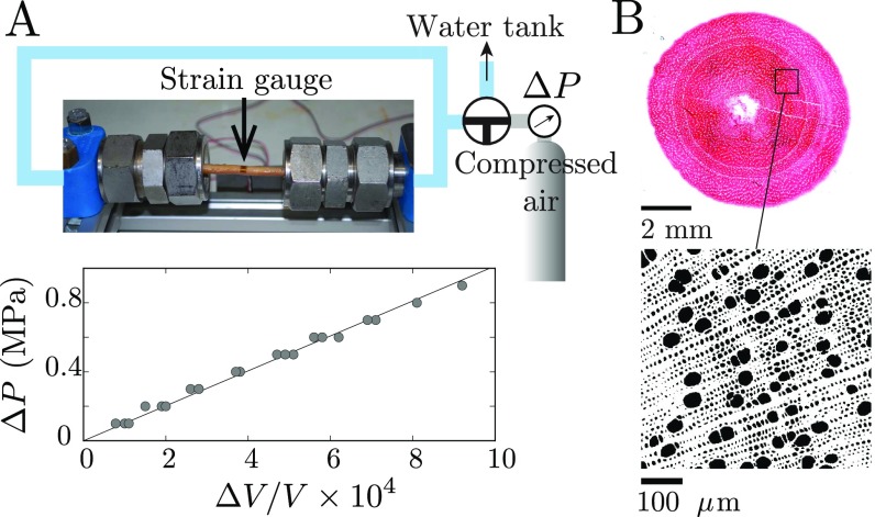
Measurement of the channel bulk modulus in poplar branches (P. alba tremula L.). (A) Experimental setup used to determine the macroscopic bulk modulus from the relationship between the pressure increments and the relative change of the branch’s volume (see plot, here GPa). (B) Cytological cross-section for measurement of the channel’s fraction (in black) and estimation of via the relation .
Fig. S5.
Normalized expelled volume of water as function of the bending deformation (the maximal deformation at the center of the branch in a four-point bending setup) on five tree species [computed from the raw data of Lopez et al., 2014 (23)]. The best quadratic fit of the data gives ().
Bending Setup for the Biomimetic Branches
The automatic bending setup for the biomimetic branches consists of a linear motor and two lever arms connected by two rotating bearings (Fig. S1 A and B). This configuration is chosen to explore a wide range of bending deformation and impose a uniform bending along the beam, while minimizing shearing effects. Two deviations from pure bending nevertheless arise with this setup. First, there exists a mean compression stress in the longitudinal direction of magnitude ( is the bending torque, is the length of the lever arm, and is the section of the beam), which adds to the bending stress (). As a consequence, the neutral surface is shifted by a distance . Second, in addition to the constant torque , there exists a torque induced by the transverse effort that varies linearly along the beam and whose maximal magnitude is , where is the length of the beam. In practice, both effects are minimized by maximizing the length of the lever arm (typically and ). Direct measurements of the curvature profile show that the curvature is approximately uniform along the beam for a wide range of imposed curvature (Fig. S1 C and D).
Energy Model for Anisotropic Beams
The energy model given in the main text can be easily extended to anisotropic beams characterized by a longitudinal Young’s modulus different from the transverse Young’s modulus , which is a first approximation of the orthotropic behavior of natural branches. The bending elastic energy per unit volume of the ovalized beam then writes (with the prefactor corresponding to a circular cross-section; ref. 36), while the compressive elastic energy per unit volume writes . The minimization of the total elastic energy thus gives: . The change of area of the beam’s cross-section associated to this transverse compression is given by: , where is the beam cross-section and is an effective 2D Poisson’s ratio in the transverse direction (38). Since by definition and assuming gives . Using the definition of the bulk modulus and the previous expressions yields:
| [S1] |
For isotropic media (), it can be shown that in the dilute channel limit with an incompressible elastic matrix (38), yielding .
Influence of the Bending Mode on the Pressure Response
In the main text, experiments on the biomimetic branches are done by applying a uniform curvature on the beam. We perform complemental experiments using a cantilever geometry, where the curvature varies linearly along the beam: (Fig. S2). Assuming that the quadratic relation between the change of channels’ volume and the bending deformation holds locally, the model predicts that the pressure response is:
| [S2] |
For a given mean curvature, the coefficient of the scaling law is therefore amplified by a factor for a linear distribution of curvature compared with the case of a uniform curvature. Such amplification is recovered in the experiments, with an amplification ratio () slightly larger than the predicted one (Fig. S2).
Extension of the Model to Beams with a Rest Curvature
The quadratic dependence of the poroelastic response observed with the synthetic branches naturally reflects the symmetry of these straight beams. For a beam with a small rest curvature , which is the case of most natural tree branches, this symmetry is broken, and one expects a linear pressure response as long as the imposed curvature increment is small compared with . To extend the model to such initially curved beams, we follow the geometrical approach proposed by ref. 41 for thin curved tubes. A beam of radius with a rest curvature is brought to the curvature . Due to the ovalization phenomenon, the cross-section is squeezed by a quantity in the curvature plane (Fig. S3). Let be the length of the fiber located at distance from the neutral surface in the rest state and its length after the increment of curvature, which brings the fiber at . Geometrical relations implies and , where is the length of the neutral surface equal in both states by definition. The corresponding longitudinal deformation associated with bending is therefore: in the limit of small rest curvature (); that is, , where , and , as defined in the main text. By minimizing the sum of the elastic bending energy and compressive energy in the transverse direction (per unit volume) with respect to , one obtains:
| [S3] |
Therefore, for a poroelastic beam with a rest curvature, the rise in pressure induced by bending is expected to vary as:
| [S4] |
When (large rest curvature and/or small deformation), the poroelastic response is linear and given by . By contrast, when (small rest curvature and/or large deformation), one recovers the quadratic relationship with the bending deformation of straight beams: .
Plant Materials
Branches of P. sylvestris with diameters ranging from 0.8 to 1.6 cm and length from 20 to 36 cm are collected on mature trees in the wild at the Puy de la Vache, Puy-de-Dôme, France [N 45.4°, E 2.6°]. Branches of Q. ilex with diameters ranging from 0.6 to 1.1 cm and lengths from 18 to 21 cm are collected from cultivated trees grown in a greenhouse. Experiments on poplars are done on hybrids (P. tremula P. alba L., clone 717-1B4) (see ref. 10 for details). One set of experiments is done on 6-mo-old stems grown in a greenhouse, with diameters ranging from 0.5 to 1.2 cm and lengths from 11 to 20 cm. A second set of experiments is done on 1- to 2-y-old branches with diameters ranging from 0.9 to 1.1 cm and lengths from 25 to 33 cm, taken from 4-y old poplars grown in an outdoor orchard at the Institut National de la Recherche Agronomique site of Crouël, Clermont-Ferrand, France [N 45.8°, E 3.2°].
Measurement of the Elastic Bulk Modulus in Woody Branches
Pressure increments are applied to the water-saturated xylem of the branch by using a compressed air bottle connected to the liquid (Fig. S4A). The relative variation of volume of the branch induced by the change of pressure is then measured by using a strain gauge glued in the transverse direction: , where is the relative variation of the branch radius and the total volume of the branch. The change of length of the branch is neglected in the computation of the variation of , as the longitudinal strain is found to be 10 times smaller than the radial deformation (consistent with the fact that the longitudinal Young’s modulus of wood is much larger than the transverse Young’s modulus). From this measurements, we obtain the macroscopic bulk modulus of the branch, defined by: . Assuming that the change of the branch volume is equal to the change of volume of the conductive channels, (the compressibility of the cell wall is negligible compared with the compressibility of the channels), and denoting the liquid fraction of the channels, , the channel bulk modulus can be obtained from the macroscopic bulk modulus as: . To measure the liquid fraction of the channel, thin cytological (16 m) transverse sections of poplar branches (without bark) are stained by using safranin and visualized with a microscope (Fig. S4B). Images are then binarized and analyzed by using the software ImageJ to compute the surface fraction of voids .
Revisiting Lopez et al. (2014)
In their study (23), Lopez et al. reported a linear correlation between the volume of expelled water (called pulse volume in the paper) and the bending deformation , in a series of four-point bending experiments on open branches from five tree species (table 1 and figure 8 of ref. 23). Such linear relationship may appear in contradiction with the quadratic law predicted by our mechanism. However, the pulse volume in their study corresponds to the volume expelled during the increment of deformation , not during the entire deformation from the initial rest state. From their raw data, we compute the total amount of water expelled at the deformation as:
| [S5] |
The total volume of water channels is then estimated as the volume of the bent lumen reported in their study for each species (the volume of the lumen is equal to the volume of the branch minus the total volume of the cell wall). With this proper representation, data from Lopez et al. (23) reveal the quadratic relationship predicted by the model (Fig. S5), with a prefactor larger but of the same order of magnitude as in our experiments (Fig. S4 Inset).
Discussion
Hydraulic pulses induced by bending were recently put forward as a promising pathway for the rapid transmission of mechanosensing information in plants. However, how such signals could be physically generated, and how they rely on the biomechanical traits of plant tissues remained poorly understood. In this work, we address these issues using a biomimetic approach. We reveal a generic mechanism for the generation of hydraulic pressure pulses under bending, both in soft artificial branches and natural tree branches. Our mechanism relies on a nonlinear coupling between the bending and transverse mode of deformation of the beam that squeezes its cross-section, by analogy with the ovalization of thin, hollow tubes. This flattening then induces a global increase of the hydraulic pressure in the conductive channels of the branch that varies quadratically with the bending strain. Hence, unlike predictions of the linear beam theory, a nonzero hydraulic pressure pulse can be produced under bending in a poroelastic beam due to nonlinear geometrical effects, independent of the material properties. This finding confirms and explains the paradox previously hypothesized about the origin of hydraulic pulses induced by bending in plants (23). In an engineering context, it could also be applied to artificial devices like microfluidic pumps or soft robots to rectify pressure and fluid flow under oscillatory motion (32, 43).
The simple poroelastic model we built shows that the key parameter controlling the amplitude of the pressure response is the elastic bulk modulus of the branch, a mechanical property that mainly depends on the Young’s modulus of the branch. The master curve that enlightens a unique mechanical law for artificial and natural branches is available in a wide range of material rigidities (Fig. 5), suggesting the robustness of the theoretical modeling. The few key parameters that drive the generation of the hydraulic pulse are basic patterns, which are common to all plants: the presence of a conducting hydraulic network in a rigid structure, without any further prerequisites about the other structural parameters. This suggests a universal physical phenomenon that occurs in all plants that daily experience the mechanical loads of the wind (44).
Our study therefore gives a physical basis for long-distance communication in plants based on hydraulic signals. However, for these pressure pulses to function as information carriers, they must fulfill two main conditions: (i) they should transfer rapidly information from the places that experience the mechanical stimuli to the apical zones that sense the signal; and (ii) they should be perceived and converted to a relevant physiological response (thigmomorphogenetic growth response).
According to our study, a bending strain of few percent caused by wind sway (44) generates a hydraulic pressure pulse of amplitude 0.01–0.1 MPa without change of conductivity (the squeezing of the cross-section is of order ). This pressure pulse first propagates ballistically at the speed of the compressive elastic waves m s−1 ( is the water density) (45), then spreads with a diffusive dynamics when viscous effects prevail over inertia. This cross-over between the ballistic and diffusive regime naturally defines an effective range of propagation without damping when the inertial timescale becomes equal to the poroelastic timescale (25), where is a longitudinal diffusion coefficient related to the channels diameter , the channel elasticity , and the water viscosity . Typical values for woody tissues give m (m, GPa, mPa s). Beyond this length, the hydraulic signal still propagates rapidly, but with a diffusive dynamics (the effective speed of the diffusion front is about 50 m s−1 for a traveling distance m).
Even though hydraulic pulses spread rapidly throughout the conductive network, whether they are perceived or not as a signal is still an open question. Typical pressure pulses induced by bending are one order of magnitude smaller in amplitude than the slow daily variation of the (negative) water pressure in the conductive network of transpiring plants (35), but their frequency is much higher (typically a few hertz). This separation of amplitude and time scales is found in most biological sensory systems (46). How this overpressure may be sensed in the apical part is still under debate, but recent works suggest that mechanosensing channels could be involved in this transduction process (11, 12), opening the pathway for ion fluxes that generate local electrical signals and molecular responses (16). Future works are needed to address these issues and establish whether thigmomorphogenesis in plants do rely on this peculiar mode of signaling: hydraulics.
Materials and Methods
Experiments on Biomimetic Branches.
Synthetic branches are made in PDMS with the Sylgard 184 Silicone Elastomer Kit using either 10% or 4% (wt) cross-linker (degassed for 30 min). The liquid PDMS is injected in a negative 3D mold made of a poly(methyl methacrylate) (PMMA) tube (length cm, inner diameter cm) containing piano strings (diameter m) fixed at both extremities in a pattern of holes drilled in a polyoxymethylene (POM) plate. Once cured (1 wk at 60 °C), the solid PDMS beam is removed from the mold and fitted into two perforated PMMA blocks. The channels are then filled with a viscous silicone oil (viscosity 1 Pas) and connected together to a differential pressure sensor. The Young’s modulus of the beam’s matrix is determined from plain slender rods of PDMS by using a tensile testing device in the linear regime of deformation (<25%). The elastic bulk modulus of the synthetic branches is determined by injecting a given amount of liquid inside the channels with a microsyringe and measuring the corresponding increase of liquid pressure. The beams are bent either manually or by using an automated bending device (see Bending Setup for the Biomimetic Branches for details). The mean curvature of the beam is measured from the difference of the angle of the beam’s profile at both extremities.
Experiments with Plant Materials.
All experiments are conducted between May and September on well-watered trees (see Plant Materials for details on the species and growing conditions). Buds and leaves are removed a few days before collecting the materials, and the scars are glued to avoid leaks during measurements. The cutting of branches and stems is done following the method described in ref. 47 to avoid any air contamination in the conducting system. The branches are then plugged to the experimental setup and flushed for several hours with degassed water to fill the conductive hydraulic network. During the bending, the branches are either in air or immersed in water to avoid evaporation. The determination of the longitudinal Young’s modulus of the branches is done after each experiment by using a standard four-point bending test. The determination of the elastic bulk modulus of the channels is done by applying pressure increments to the water-saturated xylem of the branch (Measurement of the Elastic Bulk Modulus in Woody Branches).
Refined Model.
In the Results, the quadratic relationship [1] between the hydraulic overpressure and the bending strain is obtained from simple scaling arguments, assuming a uniform transverse strain in the cross-section of the beam. Here, the prefactor of the scaling law is computed by taking into account the spatial variation of the transverse strain. For a cylindrical elastic beam of radius , bent with a uniform curvature , the balance of the bending longitudinal stress implies the existence of a compressive stress in the transverse direction due to the finite curvature of the beam. This second-order effect in the slender beam parameter is responsible for the ovalization of the cross-section and gives rise to a parabolic transverse strain field given by ref. 48:
| [2] |
where and is the height from the neutral line. To compute the liquid overpressure generated by this transverse compression field in the channel, a mean field approach is used in the limit of low channel density (low porosity). Each channel at height filled with an incompressible fluid is assumed to deform as if it was isolated in an effective infinite elastic medium and subjected to an external uniform compression field . By using the superposition principle, the relative change of volume of each channel is then given by the sum of the volume variation induced by the transverse compression strain and by the overpressure (see ref. 36, chapter 13, problem 5, and chapter 7, problem 4); that is:
| [3] |
where is the channel volume and is the channel bulk modulus as defined in the Results. In a closed system, the incompressibility of the liquid implies . Moreover, in natural branches and in our experiments, the channels are always interconnected hydraulically, so the overpressure is uniform (). Therefore, substituting Eq. 2 in Eq. 3 and summing over all channels for identical channels ( and ) gives Eq. 1 with:
| [4] |
where is the number of channels.
Acknowledgments
We thank Brigitte Girard and Pierre Conchon for their help with the wood microslices preparations on tree branches. This work was supported by Agence Nationale de la Recherche (ANR) Jeunes Chercheuses et Jeunes Chercheurs Program ARTIS Grant ANR-13-JS09-0011-01, Labex MEC Grant ANR-10-LABX-0092, the A*MIDEX Project (ANR-11-IDEX-0001-02) funded by the French government program Investissements d’avenir, and the European Research Council (ERC) under European Union Horizon 2020 Research and Innovation Program Grant 647384.
Footnotes
The authors declare no conflict of interest.
This article is a PNAS Direct Submission.
Data deposition: Data have been made available on the open-source database Zenodo at https://doi.org/10.5281/zenodo.825930.
This article contains supporting information online at www.pnas.org/lookup/suppl/doi:10.1073/pnas.1707675114/-/DCSupplemental.
References
- 1.Darwin C, Darwin F. The Power of Movement in Plants. Murray; London: 1880. [Google Scholar]
- 2.Knight TA. Account of some experiments on the descent of the sap in trees. Phil Trans Roy Soc Lond. 1803;93:277–289. [Google Scholar]
- 3.Jaffe MJ, Leopold AC, Staples RC. Thigmo responses in plants and fungi. Am J Bot. 2002;89:375–382. doi: 10.3732/ajb.89.3.375. [DOI] [PubMed] [Google Scholar]
- 4.Braam J. In touch: Plant responses to mechanical stimuli. New Phytol. 2005;165:373–389. doi: 10.1111/j.1469-8137.2004.01263.x. [DOI] [PubMed] [Google Scholar]
- 5.Telewski FW. A unified hypothesis of mechanoperception in plants. Am J Bot. 2006;93:1466–1476. doi: 10.3732/ajb.93.10.1466. [DOI] [PubMed] [Google Scholar]
- 6.Coutand C. Mechanosensing and thigmomorphogenesis, a physiological and biomechanical point of view. Plant Sci. 2010;179:168–182. [Google Scholar]
- 7.Knight MR, Smith SM, Trewavas AJ. Wind-induced plant motion immediately increases cytosolic calcium. Proc Natl Acad Sci USA. 1992;89:4967–4971. doi: 10.1073/pnas.89.11.4967. [DOI] [PMC free article] [PubMed] [Google Scholar]
- 8.Coutand C, Julien JL, Moulia B, Mauget JC, Guitard D. Biomechanical study of the effect of a controlled bending on tomato stem elongation: Global mechanical analysis. J Exp Bot. 2000;51:1813–1824. doi: 10.1093/jexbot/51.352.1813. [DOI] [PubMed] [Google Scholar]
- 9.Kern KA, Ewers FW, Telewski FW, Koehler L. Mechanical perturbation affects conductivity, mechanical properties and aboveground biomass of hybrid poplars. Tree Physiol. 2005;25:1243–1251. doi: 10.1093/treephys/25.10.1243. [DOI] [PubMed] [Google Scholar]
- 10.Coutand C, et al. Strain mechanosensing quantitatively controls diameter growth and PtaZFP2 gene expression in poplar. Plant Physiol. 2009;151:223–232. doi: 10.1104/pp.109.138164. [DOI] [PMC free article] [PubMed] [Google Scholar]
- 11.Monshausen GB, Haswell ES. A force of nature: Molecular mechanisms of mechanoperception in plants. J Exp Bot. 2013;64:4663–4680. doi: 10.1093/jxb/ert204. [DOI] [PMC free article] [PubMed] [Google Scholar]
- 12.Peyronnet R, Tran D, Girault T, Frachisse JM. Mechanosensitive channels: Feeling tension in a world under pressure. Front Plant Sci. 2014;5:558. doi: 10.3389/fpls.2014.00558. [DOI] [PMC free article] [PubMed] [Google Scholar]
- 13.Patterson MR. Role of mechanical loading in growth of sunflower (Helianthus annuus) seedlings. J Exp Bot. 1992;43:933–939. [Google Scholar]
- 14.Mousavi SAR, Chauvin A, Pascaud F, Kellenberger S, Farmer EE. GLUTAMATE RECEPTOR-LIKE genes mediate leaf-to-leaf wound signalling. Nature. 2013;500:422–426. doi: 10.1038/nature12478. [DOI] [PubMed] [Google Scholar]
- 15.Hedrich R, Salvador-Recatalà V, Dreyer I. Electrical wiring and long-distance plant communication. Trends Plant Sci. 2016;21:376–387. doi: 10.1016/j.tplants.2016.01.016. [DOI] [PubMed] [Google Scholar]
- 16.Choi WG, Hilleary R, Swanson SJ, Kim SH, Gilroy S. Rapid, long-distance electrical and calcium signaling in plants. Annu Rev Plant Biol. 2016;67:287–307. doi: 10.1146/annurev-arplant-043015-112130. [DOI] [PubMed] [Google Scholar]
- 17.Christmann A, Grill E, Huang J. Hydraulic signals in long-distance signaling. Curr Opin Plant Biol. 2013;16:293–300. doi: 10.1016/j.pbi.2013.02.011. [DOI] [PubMed] [Google Scholar]
- 18.Farmer EE, Gasperini D, Acosta IF. The squeeze cell hypothesis for the activation of jasmonate synthesis in response to wounding. New Phytol. 2014;204:282–288. doi: 10.1111/nph.12897. [DOI] [PubMed] [Google Scholar]
- 19.Ricca U. Transmission of stimuli in plants. Nature. 1926;117:654–655. [Google Scholar]
- 20.Malone M. Hydraulic signals. Phil Trans Roy Soc B Biol Sci. 1993;341:33–39. [Google Scholar]
- 21.Stahlberg R, Cosgrove D. Comparison of electric and growth responses to excision in cucumber and pea seedlings. ii. Long-distance effects are caused by the release of xylem pressure. Plant Cell Environ. 1995;18:33–41. doi: 10.1111/j.1365-3040.1995.tb00541.x. [DOI] [PubMed] [Google Scholar]
- 22.Stankovic B, Zawadzki T, Davies E. Characterization of the variation potential in sunflower. Plant Physiol. 1997;115:1083–1088. doi: 10.1104/pp.115.3.1083. [DOI] [PMC free article] [PubMed] [Google Scholar]
- 23.Lopez R, et al. Tree shoot bending generates hydraulic pressure pulses: A new long-distance signal? J Exp Bot. 2014;65:1997–2008. doi: 10.1093/jxb/eru045. [DOI] [PMC free article] [PubMed] [Google Scholar]
- 24.Biot MA. General theory of three-dimensional consolidation. J Appl Phys. 1941;12:155–164. [Google Scholar]
- 25.Dumais J, Forterre Y. “Vegetable dynamicks”: The role of water in plant movements. Annu Rev Fluid Mech. 2012;44:453–478. [Google Scholar]
- 26.Noblin X, et al. Optimal vein density in artificial and real leaves. Proc Natl Acad Sci USA. 2008;105:9140–9144. doi: 10.1073/pnas.0709194105. [DOI] [PMC free article] [PubMed] [Google Scholar]
- 27.Wheeler T, Stroock A. The transpiration of water at negative pressures in a synthetic tree. Nature. 2008;455:208–212. doi: 10.1038/nature07226. [DOI] [PubMed] [Google Scholar]
- 28.Vincent O, Marmottant P, Gonzalez-Avila S, Ando K, Ohl CD. The fast dynamics of cavitation bubbles within water confined in elastic solids. Soft Matter. 2014;10:1455–1461. doi: 10.1039/c3sm52697f. [DOI] [PubMed] [Google Scholar]
- 29.Zwieniecki MA, Haaning KS, Boyce CK, Jensen KH. Stomatal design principles in synthetic and real leaves. J R Soc Interface. 2016;13:20160535. doi: 10.1098/rsif.2016.0535. [DOI] [PMC free article] [PubMed] [Google Scholar]
- 30.Skotheim JM, Mahadevan L. Dynamics of poroelastic filaments. Proc R Soc A Math Phys Eng Sci. 2004;460:1995–2020. [Google Scholar]
- 31.Scherer GW. Bending a gel rod with an impermeable surface. J Non Cryst Solids. 1996;204:73–77. [Google Scholar]
- 32.Holmes DP, Tavakol B, Froehlicher G, Stone HA. Control and manipulation of microfluidic flow via elastic deformations. Soft Matter. 2013;9:7049–7053. [Google Scholar]
- 33.Gibson LJ, Ashby MF. Cellular Solids, Structure and Properties. Cambridge Univ Press; Cambridge, UK: 1999. [Google Scholar]
- 34.Niklas K. Plant Biomechanics: An Engineering Approach to Plant Form and Function. Univ of Chicago Press; Chicago: 1992. [Google Scholar]
- 35.Tyree MT, Zimmermann MH. Xylem Structure and the Ascent of Sap. Springer; New York: 2002. [Google Scholar]
- 36.Landau LD, Lifshitz EM. Theory of Elasticity. Elsevier; New York: 1986. [Google Scholar]
- 37.Brazier LG. On the flexure of thin cylindrical shells and other “Thin” sections. Proc R Soc A Math Phys Eng Sci. 1927;116:104–114. [Google Scholar]
- 38.Day AR, Snyder KA, Garboczi EJ, Thorpe MF. The elastic moduli of a sheet containing circular holes. J Mech Phys Solids. 1992;40:1031–1051. [Google Scholar]
- 39.Wang H. Theory of Linear Poroelasticity with Applications to Geomechanics and Hydrogeology. Princeton Univ Press; Princeton: 2000. [Google Scholar]
- 40.Crivellaro A, Schweingruber FH. Stem Anatomical Features of Dicotyledons. Kessel; Remagen, Germany: 2015. [Google Scholar]
- 41.Clark R, Reissner E. Bending of curved tubes. Adv Appl Mech. 1951;2:93–122. [Google Scholar]
- 42.Green DW, Winandy JE, Kretschmann DE. Wood Handbook: Wood as an Engineering Material. Forest Products Laboratory; Madison, WI: 1999. Mechanical properties of wood; pp. 4-1–4-45. [Google Scholar]
- 43.Shepherd RF, et al. Multigait soft robot. Proc Natl Acad Sci USA. 2011;108:20400–20403. doi: 10.1073/pnas.1116564108. [DOI] [PMC free article] [PubMed] [Google Scholar]
- 44.De Langre E. Effects of wind on plants. Annu Rev Fluid Mech. 2008;40:141–168. [Google Scholar]
- 45.Knipfer T, Steudle E. Root hydraulic conductivity measured by pressure clamp is substantially affected by internal unstirred layers. J Exp Bot. 2008;59:2071–2084. doi: 10.1093/jxb/ern064. [DOI] [PMC free article] [PubMed] [Google Scholar]
- 46.Smith CUM. Biology of Sensory Systems. John Wiley & Sons; New York: 2008. [Google Scholar]
- 47.Wheeler JK, Huggett BA, Tofte AN, Rockwell FE, Holbrook NM. Cutting xylem under tension or supersaturated with gas can generate PLC and the appearance of rapid recovery from embolism. Plant Cell Environ. 2013;36:1938–1949. doi: 10.1111/pce.12139. [DOI] [PubMed] [Google Scholar]
- 48.Ennos A, van Casteren A. Transverse stresses and modes of failure in tree branches and other beams. Proc Biol Sci. 2010;277:1253–1258. doi: 10.1098/rspb.2009.2093. [DOI] [PMC free article] [PubMed] [Google Scholar]


