Abstract
Background and Objectives:
This in vitro study seeks to evaluate and compare the marginal and internal fit of cobalt-chromium copings fabricated using the conventional and direct metal laser sintering (DMLS) techniques.
Methods:
A master model of a prepared molar tooth was made using cobalt-chromium alloy. Silicone impression of the master model was made and thirty standardized working models were then produced; twenty working models for conventional lost-wax technique and ten working models for DMLS technique. A total of twenty metal copings were fabricated using two different production techniques: conventional lost-wax method and DMLS; ten samples in each group. The conventional and DMLS copings were cemented to the working models using glass ionomer cement. Marginal gap of the copings were measured at predetermined four points. The die with the cemented copings are standardized-sectioned with a heavy duty lathe. Then, each sectioned samples were analyzed for the internal gap between the die and the metal coping using a metallurgical microscope. Digital photographs were taken at ×50 magnification and analyzed using measurement software. Statistical analysis was done by unpaired t-test and analysis of variance (ANOVA).
Results:
The results of this study reveal that no significant difference was present in the marginal gap of conventional and DMLS copings (P > 0.05) by means of ANOVA. The mean values of internal gap of DMLS copings were significantly greater than that of conventional copings (P < 0.05).
Conclusions:
Within the limitations of this in vitro study, it was concluded that the internal fit of conventional copings was superior to that of the DMLS copings. Marginal fit of the copings fabricated by two different techniques had no significant difference.
Keywords: Cement thickness, fabrication techniques, internal gap, marginal gap
INTRODUCTION
Porcelain fused to metal prosthesis has been one of the most widely used types of dental prostheses. It is composed of a metal coping or framework covered with multilayer sintered porcelain material.[1] A good marginal fit is one important requisite for the long-term success of the prosthesis.[2] A fixed dental prosthesis with excellent marginal fit may reduce risks of biological complications such as secondary caries and periodontal diseases by minimizing marginal accumulation of food, bacteria, and plaque.[1] The fit and distortion of the porcelain fused to metal crowns, including how the fit affected by the fabrication procedures has been intensely scrutinized.[3]
Today, there is no consensus regarding cement film thickness and clinical acceptance. However, long-term follow-up and laboratory studies discuss different levels of gaps for clinical acceptance.[2] A few studies on the fit of prostheses fabricated in cobalt-chromium alloy have demonstrated marginal discrepancies of 74–99 μm, with internal gaps ranging from 250 to 350 μm using laser melting technology on single crowns and with laser sintered cobalt-chromium crowns with a mean internal gap of 63 μm.[2,3,4] The use of cobalt-chromium alloy in dentistry has increased due to its low price and different fabrication methods.[2,4] Only few published studies are there on properties such as biocompatibility, long-term effects, and the fit of fixed dental prosthesis for this material and the new fabrication methods.[2,5]
The traditional technique for fabricating the metal copings of porcelain fused to metal prosthesis is the lost-wax technique using various metal alloys for casting.[3] Casting of base metal alloys is technique sensitive and due to their high hardness, trimming, and finishing of cast base metal alloys is time-consuming for dental laboratories.[4] The possible problems with this technique are making impressions in the oral cavity which may cause discomfort for patients and inaccurate marginal fit may result from contraction of impression material, distortion of wax patterns, or irregularities in the cast metal.[1] In efforts to overcome the limitations of the conventional lost-wax method, computer-aided design/computer-aided manufacturing (CAD/CAM) systems have been introduced.[1]
The newly developed direct metal laser sintering (DMLS) system is an additive metal fabrication technology.[1] Based on information received from three-dimensional (3D) computer-aided design and using a data file, metal powder is shot selectively and fused with a laser to laminate approximately a 20–60 μm thick layer with each shooting to complete a metal structure.
Advantages of the DMLS system include easy fabrication of complex shapes, operation of an automatic system, and short working time due to elimination of the procedures of fabricating a wax pattern, investing, burn out, and casting.[1] While the traditional casting method using the conventional lost-wax method might waste metal in spruing and other procedures, the DMLS system could reduce metal waste by selectively shooting the required amount. One disadvantage of the DMLS system is the cost of the equipment.[1] While an essential condition for a successful dental prosthesis is good marginal fit, there is a little data on the marginal fit of fixed dental prostheses fabricated by the DMLS system.[1] This in vitro study seeks to evaluate and compare the marginal and internal fit of cobalt-chromium copings fabricated using the conventional and DMLS techniques.
MATERIALS AND METHODS
The present study was conducted to evaluate and compare the marginal and internal fit of cobalt-chromium copings fabricated by conventional and the DMLS techniques.
Fabrication of master model
A wax pattern [Figure 1] simulating a molar tooth preparation was milled from a wax block to achieve a 360° chamfer margin with 16° of total convergence angle. The preparation had an occlusogingival height of 5 mm and diameter of 8 mm at the occlusal level and 10 mm at the cervical level. The pattern was then fixed on a wax base of dimensions 15 mm × 14 mm × 5 mm (L × W × H). The entire assembly was then cast using cobalt-chromium alloy. The metal model so obtained was measured and refined to rectify the errors made during casting [Figure 2].
Figure 1.
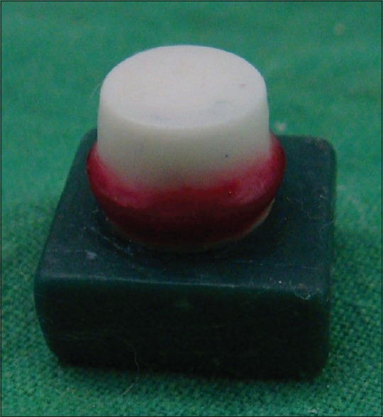
Wax pattern for master model
Figure 2.
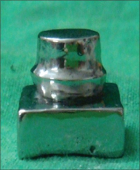
Master model
Fabrication of working models
Impression of the master die was made using silicone impression material in a custom made metal tray [Figure 3]. Working model was made using die stone as shown in Figure 4. For standardization, the working models were measured mesiodistally, occlusogingivally, and buccolingually using a metal gauge. Working models with standardized measurements were selected.
Figure 3.
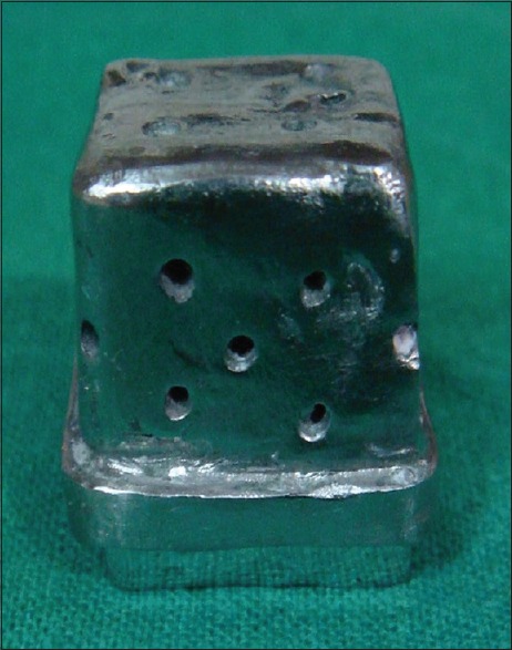
Custom made impression tray
Figure 4.
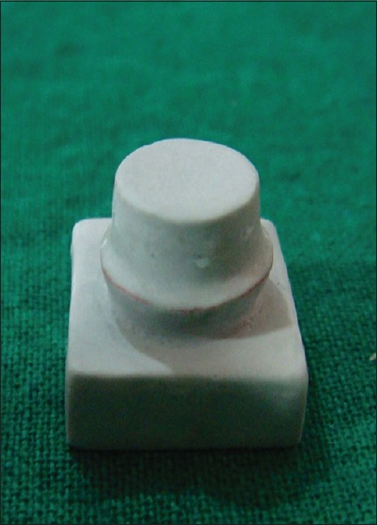
Working model
A total of thirty standardized working models made of die stone were selected. Ten working models were used for preparing DMLS copings, ten working models for preparing conventional copings, and the other ten working models for the cementation of conventional copings.
Preparation of conventional copings
The conventional copings were prepared by lost-wax technique in a centrifugal induction casting machine [Bego, Bremen, Fornex T– Figure 5]. Ten working models were selected. A single layer of die hardener and four coats of die spacer were applied on the prepared surface of the working models (50 μm). The die spacer was applied 0.5 mm short of the cervical margin. Wax patterns for copings were made with a 0.5 mm thickness using inlay wax. The thickness was standardized and measured using a wax gauge. Sprue was attached to the wax pattern, invested, and cast in the casting machine (Bego, Bremen, Fornex T). The finished copings were placed on the new working models without die spacer as shown in Figure 6. The new working models were also standardized in the similar manner by measuring the occlusogingival, mesiodistal, and buccolingual width.
Figure 5.
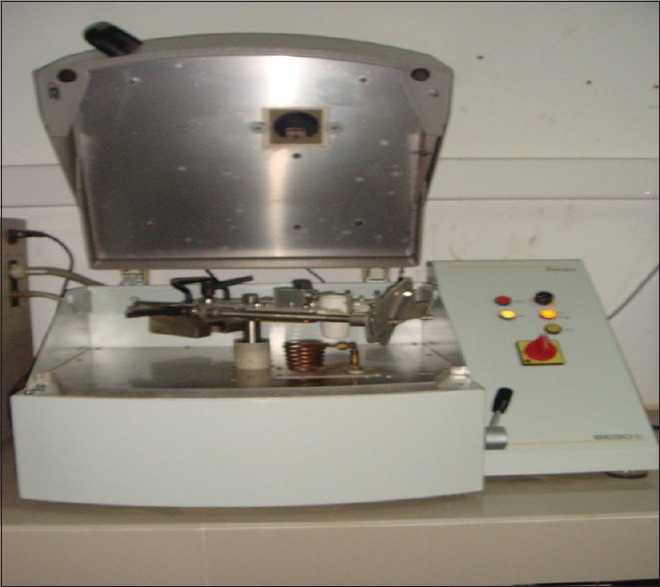
Casting machine (Bego, Bremen, Fornex T)
Figure 6.
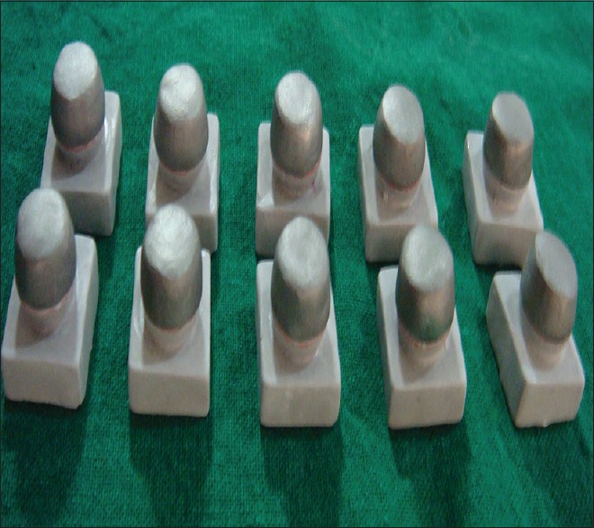
Conventional copings on the working models
Preparation of direct metal laser sintered copings
Copings were made in the DMLS machine [EOSINT M270, EOS GmbH, Germany, Figure 7]. The ten working models were read by the scanner, using Cambridge software, by an experienced dental technician. Cobalt-chromium copings of 0.5 mm thickness, with a 50 μm of cement film thickness and short of their cervical margin by 0.5 mm, were designed.
Figure 7.
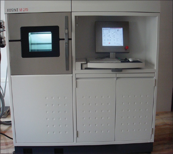
Direct metal laser sintering machine (EOSINT M270, EOS GmbH, Germany)
DMLS technology fuses metal powder into a solid part by melting it locally using the focused laser beam and was builtup additively layer by layer, using layers of 20 μm thickness. A total of 10 DMLS copings were fabricated [Figure 8].
Figure 8.
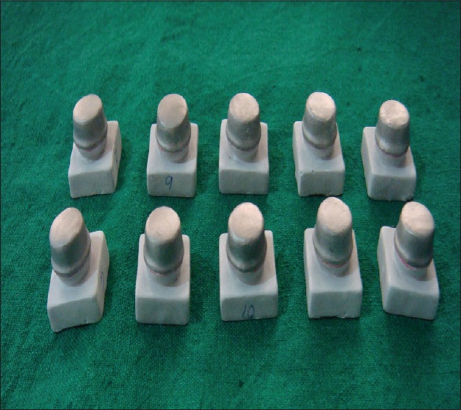
Direct metal laser sintered copings on the working models
Cementation of copings to working model
The conventional and DMLS copings were cemented to the working models using glass ionomer cement. The cement was measured and mixed according to the manufacturer's instructions and applied to the intaglio surface of the copings. Individual copings were seated on the working casts with firm finger pressure by the same operator for 2 min. Excess cement was removed with an explorer. After cementation, the specimens were stored for 24 h in room temperature before sectioning.
Measurement of marginal gap
After cementation, marginal gap of conventional copings and DMLS copings were measured at four predetermined points (one on midbuccal, midmesial, midlingual, and middistal surfaces). The measurements were made using the metallurgical microscope in micrometers and were tabulated for statistical analysis.
Sectioning of samples
A customized vice was made with a rail for standardized sectioning of samples. The samples were sectioned using a carborundum disc in a heavy duty lathe. The vice was customized on the basis of the height of the mandrel from the base of the heavy duty lathe and the width of the carborundum disc. Each sample was fixed on to the vice and sectioned into two pieces [Figure 9]. Water was sprayed to prevent production of heat. The samples were cleaned and fine finishing was done to remove the debris and measurements were done.
Figure 9.
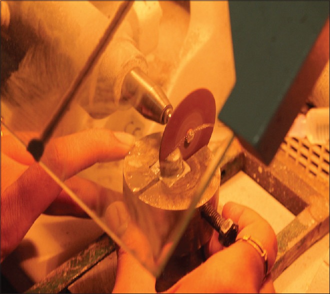
Sectioning of samples
Measuring the internal gap
The internal gap of copings prepared by conventional and DMLS techniques was measured using metallurgical microscope (Olympus BX5, Japan) calibrated by an experienced engineer according to the manufacturer's instructions. The internal gap of copings was measured at seven standardized points, two points on each axial wall, and three points on the occlusal surface. Furthermore, digital photographs, digital imaging solution based on the analysis platform, were taken with a magnification of ×50 and analyzed in a measuring program (Olympus, Japan) [Figure 10]. All measurements were made by evaluating the cement film thickness present between the coping and working die.
Figure 10.
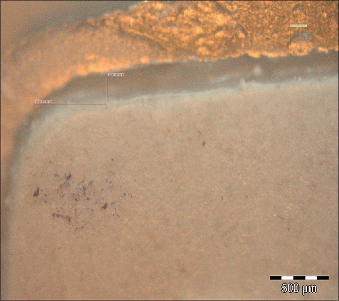
Photo showing measurements of internal gap in metallurgical microscope
RESULTS
Statistical analysis
Results were tabulated and subjected to unpaired t-test and one-way analysis of variance (ANOVA) to detect statistically significant differences. Statistical analysis was done using IBM corporation SPSS version 20 (Chicago, USA) program at a significant level of P ≤ 0.05 [Tables 1–4].
Table 1.
Comparison of the marginal gap between the conventional copings and direct metal laser sintered copings using unpaired t-test
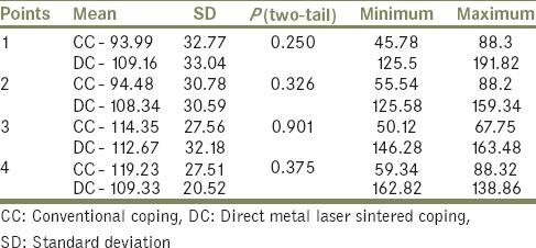
Table 4.
Internal gap of conventional copings and direct metal laser sintered copings

Table 2.
Comparison of the internal gap between the conventional copings and direct metal laser sintered copings using unpaired t-test
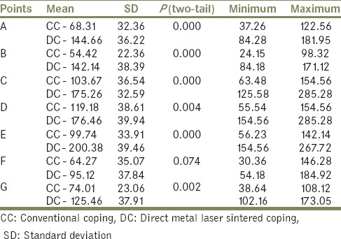
Table 3 shows comparison of the marginal gap of conventional copings and DMLS copings by means of ANOVA. There is no significant difference present in the marginal gap, with the P > 0.05.
Table 3.
Marginal gap of conventional copings and direct metal laser sintered copings using ANOVA

Table 4 shows comparison of the internal gap of conventional copings and DMLS copings by means of ANOVA. There is a significant difference present in the internal gap, with P < 0.05.
The following results were drawn from the present study:
The copings fabricated using the conventional and DMLS techniques had a comparable marginal fit without any statistically significant difference. This might be because the margin determination was done under manual adjustment
Copings fabricated using the conventional technique had a statistically significant superior internal fit when compared to that of DMLS technique. This could be because of any defects in precision of the scanner that reads the abutments, how the software can transform the scanning data into a 3D model in the computer, and the precision of the machine that will CAM the objects from the CAD data.
DISCUSSION
The objective of the present study was to evaluate and compare the marginal and internal fit of cobalt-chromium copings fabricated using the conventional casting and DMLS techniques. The conventional copings were prepared by lost-wax technique in a casting machine (Bego, Bremen, Fornex T). DMLS copings were prepared by EOSINT M 270 machine. A total of twenty samples were standardized selected, ten in each group. The copings were cemented on to their respective working models. Marginal gap was measured at four standardized points using metallurgical microscope. Each sample was standardized sectioned. The internal gap was evaluated by measuring the cement thickness between the coping and the working die at seven predetermined points using the same metallurgical microscope.
In the present study, the master model of a prepared molar tooth with a diameter of 10 mm at the cervical level was made using cobalt-chromium alloy (Colado® CC, Ivoclar vivadent AG, Germany).[6] The crown preparation was similar in volumetric size to an average molar.[6] A 360° chamfer preparation with 16° total occlusal convergence was given.[2] Cobalt-chromium metal was used because of the strength and wear resistance.[7]
The impression of the master model was made using elastomeric impression material (Elite HD +, Zhermack, Italy) using a custom made perforated metal tray (nickel-chromium alloy, girobond®, Germany) for dimensional accuracy.[8] Vertical and horizontal stops were made on to the impression tray to standardize the impression technique. Finger pressure was used to mimic a clinical situation.[2] Thirty different working models were produced using the same type of die stone (Type 4 Diestone, Pastel Rock, Kerr, Italy). Type 4 die stone has high strength, low expansion, and ideal working characteristics. Thus, the problem of wear of master model was eliminated.[2] For standardization, the working models were measured mesiodiatally, occlusogingivally, and buccolingually using a metal gauge (6368 Medis CЄ). Working models with standardized measurements were selected.
A uniform die spacer thickness of 50 μm2 within 0.5 mm short of the cervical margin was used in both fabrication techniques.[9] In conventional technique, the die spacer (Pro-Die Spacer, al dente, Germany) was applied according to the manufacturer's recommendation. In DMLS technique, it is controlled by computer software (PSW Software, EOS GmbH, Germany).
The thickness of wax pattern (Renfert, Germany) was standardized by measuring using a wax gauge. Another person examined and accepted the waxing.[2] A ring-free casting technique was used to minimize the distortion.[2,10] Outer surface polishing was done in the same way for both fabrication techniques using carbide burs.[2]
In conventional lost-wax technique, some risk factors that can lead to distortion are the use of spacer to obtain a thickness of 50 μm, manual waxing, removing the wax to adapt it on the cone, the thickness of the wax, storing time, and operator skill. To minimize some of these factors, the same operator performed the waxing and casting.[2]
For standardization, cobalt-chromium alloy (EOS Cobalt Chrom SP2, EOS, Germany) was used for DMLS copings[1] and cobalt-chromium alloy (Colado® CC, Ivoclar vivadent AG, Germany) for fabrication of copings using conventional technique.[9] Even though nickel-chromium alloy is widely used for conventional casting technique, a recent investigation by Akova et al. showed that the marginal fit of conventionally cast nickel-chromium and cobalt-chromium copings was not significantly different.[5]
Glass ionomer cement (GC Gold label, luting and lining cement, GC Corporation, Tokyo, Japan) was used for cementation since it is most widely used in cementation of metal ceramic crowns.[11] The manufacturer's instructions for powder-liquid ratio and manipulation of cement were followed.[11] The seating force applied in this study was finger pressure, which can be reproduced clinically.[12] Weaver et al. determined that the seating force did not affect the degree of marginal discrepancies.[12,13] In conventional technique, the finished copings were placed on the working models without die spacer. The new working models were also standardized in the similar manner by measuring the occlusogingival, mesiodistal, and buccolingual width.
Marginal gap was measured before sectioning thus any distortion if present during sectioning was avoided. A customized vice was made with a rail for standardizing the sectioning of samples.[2] The samples were sectioned using a carborundum disc with diameter of 3.5 cm and width of 0.5 mm (LM Abrasive, Italy) in a heavy duty lathe (Ray Foster, Foster alloy grinder, Model AGO3, Serial 9151, USA).[2] The vice was customized on the basis of the height of the mandrel from the base of the heavy duty lathe and the width of the carborundum disc. Each sample was fixed on to the vice and sectioned into two pieces.[2] Water was sprayed to prevent heat production. The samples were cleaned and fine finishing (emery paper No: 00) was done to remove the debris and measurement was done. The finishing was always done in a direction away from the die. Longitudinal sectioning was done to measure the internal gap on the two axial walls as well as on the occlusal surface.[2] In the present study, both vertical gap and marginal gap along the horizontal planes were examined.
For measuring marginal and internal fit of dental prostheses, several methods have been used in previous studies: (1) a direct measuring method measures the gap or amount of cement directly by microscope after setting the dental prosthesis on the tooth model and sectioning it; (2) using silicone replica, the thickness of silicone located between the dental prosthesis and tooth model is measured by microscope; (3) a recently introduced technique using X-ray microcomputed tomography that involves shooting the inner side of the dental prosthesis.[1]
In the present study, direct measuring method that measures the gap or amount of cement directly by microscope after cementation of the metal copings on the working model and sectioning was used, to stimulate a clinical situation.[2] The direct measuring method has a critical problem of destroying the metal copings and the working model. In this study, damaged prostheses and tooth models were discarded.
All measurements were made using metallurgical microscope of ×50 magnification (Olympus BX51, Japan) that was calibrated by an experienced engineer according to the manufacturer's instructions. Furthermore, digital photographs (digital imaging solution based on the analysis platform) were taken with a magnification of ×50 and analyzed in a measuring program (Olympus, Japan).
The statistical analysis was done using the Microsoft Office Excel 2007, USA, and statistical software IBM CORPORATION SPSS Version 20 (Chicago, USA).[1]
Marginal fit of copings
According to Sulaiman et al.[1,14] and Mclean and von Fraunhofer,[1,2,15] the acceptable mean marginal gap is 100–120 μm. The mean of marginal fit of conventional copings was 105.52 μm and that of DMLS copings was 109.87 μm. There is no statistically significant difference in the mean of the marginal fit between the two groups (P > 0.05). The marginal gap measured is within the normal limits.
Internal fit of copings
The mean internal fit of conventional copings was 83.37 μm and that of DMLS copings was 151.35 μm. The mean internal fit of copings showed that the conventional copings had better fit. There is a significant difference of the internal fit in the copings prepared by two methods (P < 0.05). The internal fit in both types of copings had higher values on the occlusal aspect of the prepared surface when compared to the axial wall.
The results of the present study are supported by the investigation done by Ucar et al. that reported insignificant difference between marginal gap of direct metal sintered system and the conventional method.[4] They also reported that the total amount of internal gap measured by weight of filled light body silicone was significantly larger in DMLS system compared to the conventional method.
The result of the present study is also consistent with the study done by Kim et al., which reported that selective laser sintered (SLS) group cores had higher values of marginal and internal gaps than the casting group cores, and the difference was statistically significant.[9] The finished metal ceramic crown ga P values were also significantly higher in the SLS group compared to the casting group.
In another study, Kim et al. reported that marginal fit of the DMLS system appears significantly inferior compared to that of the conventional lost-wax technique and slightly larger than the acceptable range.[1] They concluded that for the clinical application of DMLS crowns, further improvement of DMLS system may be required.
The result is inconsistent with a previous investigation by Örtorp et al. that has reported superior fit of DMLS system compared to the conventional method.[2]
In vitro studies present better quality of fit in a controlled laboratory environment with optimal circumstances than in a clinical setting. However, the fabrication procedures for dental restorations in the dental laboratory do affect the fit more than the study design.[2] The main clinical and laboratory variables are impression making, master cast fabrication, die spacer, fitting procedures, and cementation. DMLS technique could minimize some of these variables since fewer critical manual steps are present.[2] However, there are three main factors that could affect the fit: the precision of the scanner that reads the abutments, how the software can transform the scanning data into a 3D model in the computer, and the precision of the machine that will CAM the objects from the CAD data.[8,16]
Shortcomings of this study might be the defects in the cementation method; here, finger pressure was used. Even though this method simulates the cementation of fixed restoration, it may vary with each sample. In a study by Quante et al., the seating pressure was standardized as 50N using a loading device.[3] Other shortcomings can be defects in cement in the area of measurement. Measurements on longitudinally sectioned crowns provide only two-dimensional information in the plane of sections; 3D volume between the crown and their dies cannot be assessed. Furthermore, the present study was done under in vitro conditions; the results may vary in oral environment.
Future research should include measurement of the mechanical properties, surface characteristics, metal to ceramic bond strength, and to assess the 3D volume between the crowns fabricated using the laser sintered cobalt-chromium alloy as well as laser-melting technology and their dies, along with investigation of the biocompatibility of the crowns prepared by laser sintering and laser melting technique (SLM). SLM is an emerging new additive technique designed to use a high-power density laser to melt and fuse metallic powder together. Unlike laser sintered technique, SLM fully melt the alloy particles into a solid 3D-crown.
For the CAD/CAM technique, development could probably speed up production by excluding time-consuming steps. These advances and the rapid development of digitized processes will continue, making this computerized technique more cost-effective and flexible with better accuracy and precision. Initially, a new technique is often costly, which is a potential limitation.[16]
CONCLUSIONS
Within the limitations of this in vitro study, it was concluded that the internal fit of conventional copings was superior to that of the DMLS copings. Marginal fit of the copings fabricated by two different techniques had no significant difference.
Financial support and sponsorship
Nil.
Conflicts of interest
There are no conflicts of interest.
REFERENCES
- 1.Kim KB, Kim WC, Kim HY, Kim JH. An evaluation of marginal fit of three-unit fixed dental prostheses fabricated by direct metal laser sintering system. Dent Mater. 2013;29:e91–6. doi: 10.1016/j.dental.2013.04.007. [DOI] [PubMed] [Google Scholar]
- 2.Örtorp A, Jönsson D, Mouhsen A, Vult von Steyern P. The fit of cobalt-chromium three-unit fixed dental prostheses fabricated with four different techniques: A comparative in vitro study. Dent Mater. 2011;27:356–63. doi: 10.1016/j.dental.2010.11.015. [DOI] [PubMed] [Google Scholar]
- 3.Quante K, Ludwig K, Kern M. Marginal and internal fit of metal-ceramic crowns fabricated with a new laser melting technology. Dent Mater. 2008;24:1311–5. doi: 10.1016/j.dental.2008.02.011. [DOI] [PubMed] [Google Scholar]
- 4.Ucar Y, Akova T, Akyil MS, Brantley WA. Internal fit evaluation of crowns prepared using a new dental crown fabrication technique: Laser-sintered Co-Cr crowns. J Prosthet Dent. 2009;102:253–9. doi: 10.1016/S0022-3913(09)60165-7. [DOI] [PubMed] [Google Scholar]
- 5.Akova T, Ucar Y, Tukay A, Balkaya MC, Brantley WA. Comparison of the bond strength of laser-sintered and cast base metal dental alloys to porcelain. Dent Mater. 2008;24:1400–4. doi: 10.1016/j.dental.2008.03.001. [DOI] [PubMed] [Google Scholar]
- 6.Gassino G, Barone Monfrin S, Scanu M, Spina G, Preti G. Marginal adaptation of fixed prosthodontics: A new in vitro 360-degree external examination procedure. Int J Prosthodont. 2004;17:218–23. [PubMed] [Google Scholar]
- 7.Roach M. Base metal alloys used for dental restorations and implants. Dent Clin North Am. 2007;51:603–27, vi. doi: 10.1016/j.cden.2007.04.001. [DOI] [PubMed] [Google Scholar]
- 8.Bhaskaran E, Azhagarasan NS, Miglani S, Ilango T, Krishna GP, Gajapathi B, et al. Comparative evaluation of marginal and internal gap of Co-Cr copings fabricated from conventional wax pattern, 3D printed resin pattern and DMLS tech: An in vitro study. J Indian Prosthodont Soc. 2013;13:189–95. doi: 10.1007/s13191-013-0283-5. [DOI] [PMC free article] [PubMed] [Google Scholar]
- 9.Kim KB, Kim JH, Kim WC, Kim HY, Kim JH. Evaluation of the marginal and internal gap of metal-ceramic crown fabricated with a selective laser sintering technology: Two- and three-dimensional replica techniques. J Adv Prosthodont. 2013;5:179–86. doi: 10.4047/jap.2013.5.2.179. [DOI] [PMC free article] [PubMed] [Google Scholar]
- 10.Lombardas P, Carbunaru A, McAlarney ME, Toothaker RW. Dimensional accuracy of castings produced with ringless and metal ring investment systems. J Prosthet Dent. 2000;84:27–31. doi: 10.1067/mpr.2000.107783. [DOI] [PubMed] [Google Scholar]
- 11.Gonzalo E, Suárez MJ, Serrano B, Lozano JF. Comparative analysis of two measurement methods for marginal fit in metal-ceramic and zirconia posterior FPDs. Int J Prosthodont. 2009;22:374–7. [PubMed] [Google Scholar]
- 12.Kokubo Y, Ohkubo C, Tsumita M, Miyashita A, Vult von Steyern P, Fukushima S, et al. Clinical marginal and internal gaps of Procera AllCeram Crowns. J Oral Rehabil. 2005;32:526–30. doi: 10.1111/j.1365-2842.2005.01458.x. [DOI] [PubMed] [Google Scholar]
- 13.Weaver JD, Johnson GH, Bales DJ. Marginal adaptation of castable ceramic crowns. J Prosthet Dent. 1991;66:747–53. doi: 10.1016/0022-3913(91)90408-o. [DOI] [PubMed] [Google Scholar]
- 14.Sulaiman F, Chai J, Jameson LM, Wozniak WT. A comparison of the marginal fit of In-Ceram, IPS Empress, and Procera crowns. Int J Prosthodont. 1997;10:478–84. [PubMed] [Google Scholar]
- 15.McLean JW, von Fraunhofer JA. The estimation of cement film thickness by an in vivo technique. Br Dent J. 1971;131:107–11. doi: 10.1038/sj.bdj.4802708. [DOI] [PubMed] [Google Scholar]
- 16.Venkatesh KV, Nandini VV. Direct metal laser sintering: A digitised metal casting technology. J Indian Prosthodont Soc. 2013;13:389–92. doi: 10.1007/s13191-013-0256-8. [DOI] [PMC free article] [PubMed] [Google Scholar]


