Abstract
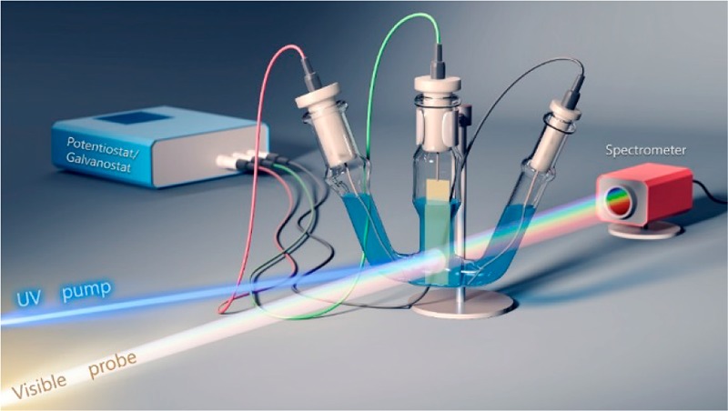
The charging of a mesoscopic TiO2 layer in a metal halide perovskite solar cell can influence the overall power conversion efficiency. By employing CsPbBr3 films deposited on a mesoscopic TiO2 film, we have succeeded in probing the influence of electrochemical bias on the charge carrier recombination process. The transient absorption spectroscopy experiments conducted at different applied potentials indicate a decrease in the charge carrier lifetimes of CsPbBr3 as we increase the potential from −0.6 to +0.6 V vs Ag/AgCl. The charge carrier lifetime increased upon reversing the applied bias, thus indicating the reversibility of the photoresponse to charging effects. The ultrafast spectroelectrochemical experiments described here offer a convenient approach to probe the charging effects in perovskite solar cells.
Utilizing metal halide perovskites beyond the popular application of photovoltaics requires better understanding of their optoelectronic properties.1−3 Properties such as excitation intensity dependent emission yield4 and spontaneous emission5,6 have drawn considerable attention to these materials as possible active components in lasing and light emitting devices.7−9 Efforts have been made to establish the nonthermalized relaxation of hot electrons, charge carrier recombination processes,1,2,10,11 and charge transport as well as the role of surface defects through time-resolved absorption and emission spectroscopy. Another important phenomenon is the mobility of halide ions under light irradiation.12−15 This behavior becomes especially apparent in mixed halide films as one observes photoinduced segregation under light irradiation.14,16,17,3−5
The greater mobility of electrons and holes in metal halide perovskites is facilitated by the screening of charge carriers.18 During the operation of photovoltaic devices, however, charge carrier recombination directly competes with the extraction of charge carriers through the respective interface with the electron transport layer (ETL) and the hole transport layer (HTL). Under continuous illumination, the accumulation of charge carriers at the ETL and HTL shifts the Fermi level of the two electrodes close to the respective band edges thus creating a potential gradient within the device. This anomalous electrical potential distribution across the layers of CsPbBr3 solar cells under different illuminations have been mapped using Kelvin probe force microscopy.19 The role of TiO2, considered to be an electron transport layer, continues to be elusive, because of its ability to capture and store electrons.20−22 For example, light soaking or application of a bias before J–V analysis of results in greater efficiency of the solar cell.23 Furthermore, electron storage in the TiO2 layer often leads to higher photovoltage and/or induced hysteresis in J–V curves.24,25
Although a few studies exist to probe the fate of charge carriers under solar cell operation conditions,19,26,27 there is a need to better understand how the electron storage in the ETL influences the charge carrier recombination in perovskite films. Such effects can be well studied by utilizing the principles of semiconductor photoelectrochemistry.20,28,29 However, the difficulty in applying electrochemistry principles to perovskite films arises from stability issues.30−32 Careful choice of organic solvent and electrolyte is needed to conduct electrochemical and spectroelectrochemical experiments.
To further clarify the charging of TiO2 films and its influence on the excited state behavior of perovskite films, we have now probed the charge carrier recombination of CsPbBr3 films deposited on a mesoscopic TiO2 layer at different electrochemical biases. By employing a narrow electrochemical window between −0.6 and +0.6 V vs Ag/AgCl we were able to conduct spectroelectrochemical experiments with good reversibility. Ultrafast spectroelectrochemical measurements that elucidate the influence of electrochemical bias on the bimolecular charge recombination are discussed.
The CsPbBr3 nanocrystals prepared by hot injection method were spin-cast on bare and TiO2-coated fluorine doped tin oxide (FTO) glass slides using a previously reported method.33Full experimental details can be found in the Supporting Information.
Establishing the Electrochemical Stability Window. The stability of CsPbBr3 films in Bu4NPF6/dichloromethane (DCM) solution has enabled us to conduct electrochemical and spectroelectrochemical measurements on this system. Figure 1 shows the cyclic voltammograms recorded separately with anodic and cathodic scans using two different electrodes. The CsPbBr3 exhibits a reduction peak at −1.4 V vs Ag/AgCl corresponding to the reduction of Pb2+ to Pb0 and an oxidation peak at +0.85 V vs Ag/AgCl corresponding to the oxidation of Br– ions. The irreversibility of these peaks suggests that these peaks arise from the cathodic and anodic corrosion, and thus partial decomposition, of the perovskite material. It is interesting to note that similar reduction and oxidation peaks were used to estimate the conduction and valence band energies of colloidal perovskite nanocrystals32 and organic semiconductors.34 Given the irreversibility of these peaks, it raises an important question of whether one can consider anodic and cathodic corrosion potentials to represent band energy positions. The expanded current scale shows the onset potentials that induce corrosion (oxidation and reduction onset seen around +0.65 and −1.2 V vs Ag/AgCl, respectively). The inactivity of CsPbBr3 film between these two onsets offers an electrochemical window to carry out spectroelectrochemical measurements. Thus, we selected a potential window of −0.6 to +0.6 V vs Ag/AgCl for spectroelectrochemical investigations of FTO/CsPbBr3 and FTO/TiO2/CsPbBr3 electrodes. The absorption spectra recorded before and after the electrochemical cycling within this window showed very little changes (Figure S1).
Figure 1.
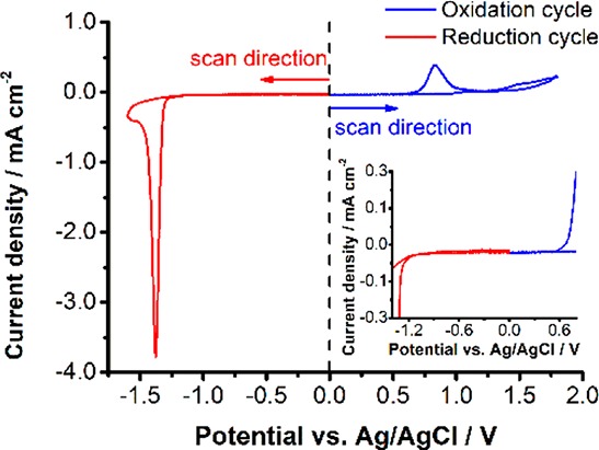
Cyclic voltammograms of FTO/TiO2/CsPbBr3 films in deaerated DCM containing 0.1 M Bu4NPF6 electrolyte (scan rate = 10 mV s–1). Two separate electrodes were employed to probe the anodic and cathodic scans. A magnified region is shown in the inset for the better visibility of the onset potentials of the oxidative and reductive processes.
Transient Absorption of CsPbBr3 with Applied Bias. The low exciton binding energy facilitates charge separation following the bandgap excitation of perovskites. The charge separation and charge recombination process in metal halide perovskite films can be readily probed through transient absorption spectroscopy.35−39Figure 2 shows the time-resolved transient absorption spectra of FTO/TiO2/CsPbBr3 electrodes while being held at four different applied potentials. The time-resolved spectra of a FTO/TiO2/CsPbBr3 electrode recorded without applied bias is shown in the Supporting Information (Figure S2). The disappearance of the excitonic band, as indicated by the bleaching at 520 nm, represents charge separation. With increasing time, the bleaching at 520 nm recovers as the photogenerated electrons and holes combine.35 The time-resolved spectra recorded at −0.4 and +0.4 V show very similar features to those recorded in the absence of applied bias. Thus, qualitatively, the applied bias has no effect on the spectral evolution of transients in this potential regime. On the other hand, the spectra recorded at extreme cathodic (−1.2 V) and anodic (+1.0 V) potentials show variation in the spectral features with recovery time. In addition, the maximum bleaching intensity is significantly diminished. Thus, at these extremes a major fraction of the perovskite has degraded and become nonresponsive to excitation. These discrepancies in the transient absorption reaffirm the instability of the perovskite film at these electrochemical bias potentials (in close agreement with cyclic voltammetry).
Figure 2.
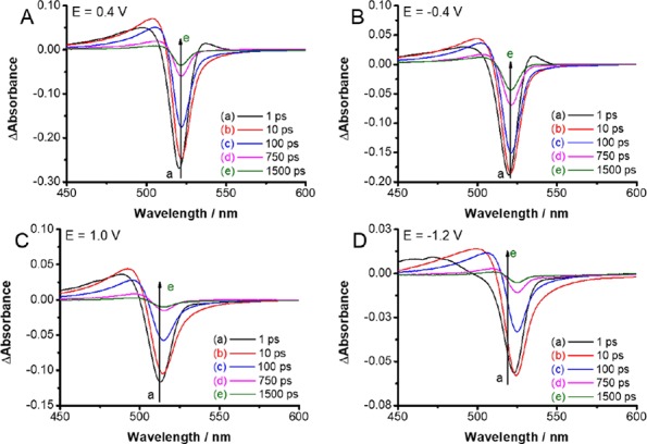
Time-resolved transient spectra recorded following 387 nm laser pulse excitation (4 μJ cm–2) of FTO/TiO2/CsPbBr3 electrode in a spectroelectrochemical cell with deaerated DCM containing 0.1 M Bu4NPF6 electrolyte. The spectra were recorded at applied potentials of (A) +0.4 V; (B) −0.4 V; (C) +1.0 V, and (D) −1.2 V vs Ag/AgCl.
Effect of Electrochemical Bias on the Charge Carrier Recombination. To further probe the effect of electrochemical bias on the charge carrier recombination in CsPbBr3 films we monitored the bleaching recovery (520 nm) at several different potential values from −0.6 to +0.6 V vs Ag/AgCl. The bleaching recovery follows simple second order decay.35 The contribution of trapped charge carriers at high excitation intensity becomes negligible.4 We also maintained similar magnitude of bleaching (ΔA = −0.25 at 520 nm) so that the initial charge carrier concentration is the same for all sets of measurements. The bleaching recovery profiles recorded at different applied potentials and the fitting of the data to second order kinetics (1/ΔA versus time) are shown in Figure 3A,B, respectively. Because the initial carrier concentrations were kept similar in all these bleaching recovery experiments, we can directly compare the slopes to obtain relative pseudo-first-order rate constants or apparent lifetimes of charge carriers.
Figure 3.
(A) Bleaching recovery profiles, (B) kinetic fit 1/ΔA vs time, and (C) relative pseudo-first-order rate constants determined from the slope of plots in panel B with the dashed line to guide the eye (the magnitude of bleaching was kept constant at −0.25 for all of these experiments so that initial charge carrier concentration is the same in all experiments). The applied potentials ranged from −0.6 to +0.6 V vs. Ag/AgCl. Experimental conditions were the same as in Figure 2.
The pseudo-first-order rate constants measured at different applied potentials showed an interesting trend as we increase the applied bias from −0.6 to +0.6 V in steps (Figure 3C). At 0.0 V and more negative potentials, the rate constant of charge carrier recombination showed only a small variation. The apparent rate constant k (pseudo-first-order) obtained from the slope was ∼2 × 10⁹ s–1 at −0.6 V and ∼2.5 × 10⁹ s–1 at 0 V, respectively. On the other hand, we observe an increase by a factor of 3 in the bleaching recovery rate constant as we increased the applied bias from 0 V to +0.6 V. Because electrons are depleted from the TiO2 layer under anodic bias, one can expect an additional pathway for photogenerated electrons to participate in the charge injection into TiO2 film (kET). The competing charge injection process thus renders faster bleaching recovery at anodic bias. These observations are consistent with the mechanism of charge injection from excited molecular sensitizer into TiO2 that is influenced by applied bias.28,29
Reversibility of Bleaching Recovery Kinetics to Applied Bias. In another, separate experiment we recorded transient absorption spectra under a forward scan (−0.6 to +0.5 V) followed by a reverse scan (+0.5 to −0.6 V). The lifetimes derived from the inverse slope of 1/ΔA versus time plots are taken as a measure for comparison. These apparent lifetimes obtained at set potentials during forward and reverse scans are presented in Figure 4A.
Figure 4.
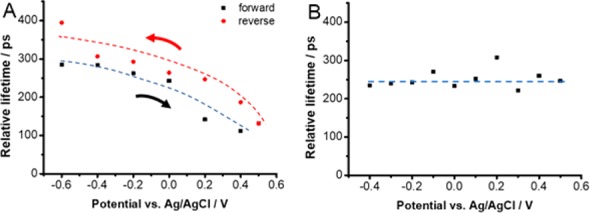
Dependence of bleaching recovery lifetime determined from the inverse slope of the kinetic fit of 1/ΔA vs time. Measurements were carried out with (A) FTO/TiO2/CsPbBr3 and (B) FTO/CsPbBr3 electrodes in deaerated DCM containing 0.1 M Bu4NPF6 electrolyte. The electrodes were biased at set potentials in the range −0.6 to +0.5 V vs Ag/AgCl and excited with 387 nm laser pulse to record time-resolved transient absorption spectra.
The decay profiles recorded at a set potential during forward and reverse scans showed the same trend of dependence on the applied bias. There seems to be a small hysteresis in the measured lifetimes when the scan is reversed. Additionally, spectra recorded for both the forward and reverse scans show no change in the shape of the features (Figure S3).
To check the hypothesis that electron accumulation in TiO2 film increases the lifetime of photogenerated electrons, we carried out spectroelectrochemical experiments with FTO/CsPbBr3 film (i.e., without TiO2 layer). Interestingly the bleaching recovery is not influenced by the applied electrochemical bias (at least within the studied time-range). The bleaching recovery lifetime remains unchanged at applied potentials in the range of −0.6 to +0.5 V vs Ag/AgCl (Figure 4B). These experimental results further elucidate the role of TiO2 in influencing the charge carrier recombination processes in perovskite films.
The Influence of TiO2 Layer on Bleaching Recovery Lifetime. The results presented in Figures 3 and 4 show the decrease in bleaching recovery time as we subject the FTO/TiO2/CsPbBr3 electrode to anodic (positive) bias. Because the bleaching is indicative of the charge separation, its recovery represents the charge recombination. Hence, one can relate the measured lifetime to electron survivability following bandgap excitation of the perovskite film. The band energy diagram in Figure 5 shows a possible scenario of Fermi level changes during open circuit and electrochemical bias conditions. The mesoscopic TiO2 layer, which is in contact with perovskite films, responds to applied bias by accumulating electrons under negative bias or depleting electrons under positive bias. Earlier studies carried out with TiO2 films alone or dye sensitized SnO2 films have shown the electron accumulation under negative bias.20,40 If the TiO2 film has excess electrons, as in the case of negative applied bias, we see suppression of electron transfer from excited perovskite to TiO2. Hence charge carrier recombination is the only process dictating the carrier lifetime. On the other hand, under anodic bias, the electron transfer from excited CsPbBr3 to TiO2 is greatly favored and this process now competes with recombination with holes. As a result, the bleaching recovery rate constant increases (or lifetime decreases) as the FTO/TiO2/CsPbBr3 electrode is subjected to positive bias.
Figure 5.
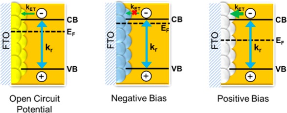
Schematic diagram illustrating the band energies and the Fermi level response to applied bias. The charge transfer from excited perovskite to TiO2 (kET) competes with the charge recombination (kr) and is influenced by the electron accumulation (or depletion) during electrochemical bias.
The role of mesoscopic TiO2 films in perovskite solar cells remains an intrigue. Perovskite solar cells can perform well without the presence of a TiO2 mesoscopic layer. For example, planar MAPbI3 based solar cells with a different ETL (e.g., fullerenes) can deliver efficiencies in the range of 20%.41,42 Yet, the champion cells that utilize mesoscopic metal oxide architecture exhibit superior performance.43 Thus, the role of TiO2 as an ETL that captures electrons from excited CsPbBr3 seems to play an important role in delivering superior device performance. The influence of electron accumulation (or depletion) on the charge recombination rate is a good indication why higher efficiencies are observed in photovoltaic devices containing mesoscopic TiO2 films.
It has been a common practice to manipulate the J–V characteristics through light soaking or applying cathodic bias.25 The perovskite solar cells show higher efficiency as the cells pretreated with cathodic bias (or light soaking) exhibit higher photovoltage. Under these pretreatment conditions, electron accumulation occurs in the TiO2 film as reflected from a small increase in photovoltage. In fact, in our previous report on best practices in solar cell characterization, we were able to demonstrate the improvement in power conversion efficiency measurement of a poorly performing solar cell through pretreatment at a negative bias.23 Indeed, the spectroelectrochemical experiments presented in this study show the effect of cathodic bias on increasing the carrier lifetime. More generally, the in situ electrochemical transient absorption measurement can be a useful tool to probe the electron injection process from the excited perovskite film to the ETL and thus allow a convenient evaluation tool for different perovskite/ETL pairs.
Acknowledgments
P.V.K. acknowledges support by the Division of Chemical Sciences, Geosciences, and Biosciences, Office of Basic Energy Sciences of the U.S. Department of Energy (award DE-FC02-04ER15533). R.S. acknowledges support of King Abdullah University of Science and Technology (KAUST-Award OCRF-2014-CRG3-2268). This collaborative research received funding from the European Research Council (ERC) under the EU’s Horizon 2020 research and innovation program (GFS and CJ, grant agreement No 716539). ELI-ALPS is supported by the EU and cofinanced by the European Regional Development Fund (GOP-1.1.1-12/B-2012-000, GINOP-2.3.6-15-2015-00001). This is contribution number NDRL No. 5191 from the Notre Dame Radiation Laboratory.
Supporting Information Available
The Supporting Information is available free of charge on the ACS Publications website at DOI: 10.1021/jacs.7b10958.
Experimental methods, film preparation, spectroscopic and spectroelectrochemical measurements (PDF)
Author Contributions
# Contributed equally to this work.
The authors declare no competing financial interest.
Supplementary Material
References
- Manser J. S.; Christians J. A.; Kamat P. V. Chem. Rev. 2016, 116, 12956. 10.1021/acs.chemrev.6b00136. [DOI] [PubMed] [Google Scholar]
- De Angelis F.; Meggiolaro D.; Mosconi E.; Petrozza A.; Nazeeruddin M. K.; Snaith H. J. ACS Energy Lett. 2017, 2, 857. 10.1021/acsenergylett.7b00217. [DOI] [Google Scholar]
- Huang H.; Bodnarchuk M. I.; Kershaw S. V.; Kovalenko M. V.; Rogach A. L. ACS Energy Lett. 2017, 2, 2071. 10.1021/acsenergylett.7b00547. [DOI] [PMC free article] [PubMed] [Google Scholar]
- Draguta S.; Thakur S.; Morozov Y. V.; Wang Y.; Manser J. S.; Kamat P. V.; Kuno M. J. Phys. Chem. Lett. 2016, 7, 715. 10.1021/acs.jpclett.5b02888. [DOI] [PubMed] [Google Scholar]
- Milot R. L.; Eperon G. E.; Green T.; Snaith H. J.; Johnston M. B.; Herz L. M. J. Phys. Chem. Lett. 2016, 7, 4178. 10.1021/acs.jpclett.6b02030. [DOI] [PubMed] [Google Scholar]
- Zheng K.; Žídek K.; Abdellah M.; Chen J.; Chábera P.; Zhang W.; Al-Marri M. J.; Pullerits T. ACS Energy Lett. 2016, 1, 1154. 10.1021/acsenergylett.6b00352. [DOI] [Google Scholar]
- Protesescu L.; Yakunin S.; Bodnarchuk M. I.; Krieg F.; Caputo R.; Hendon C. H.; Yang R. X.; Walsh A.; Kovalenko M. V. Nano Lett. 2015, 15, 3692. 10.1021/nl5048779. [DOI] [PMC free article] [PubMed] [Google Scholar]
- Jurow M. J.; Lampe T.; Penzo E.; Kang J.; Koc M. A.; Zechel T.; Nett Z.; Brady M.; Wang L.-W.; Alivisatos A. P.; Cabrini S.; Brütting W.; Liu Y. Nano Lett. 2017, 17, 4534. 10.1021/acs.nanolett.7b02147. [DOI] [PubMed] [Google Scholar]
- Congreve D. N.; Weidman M. C.; Seitz M.; Paritmongkol W.; Dahod N. S.; Tisdale W. A. ACS Photonics 2017, 4, 476. 10.1021/acsphotonics.6b00963. [DOI] [Google Scholar]
- Wehrenfennig C.; Liu M.; Snaith H. J.; Johnston M. B.; Herz L. M. J. Phys. Chem. Lett. 2014, 5, 1300. 10.1021/jz500434p. [DOI] [PubMed] [Google Scholar]
- Johnston M. B.; Herz L. M. Acc. Chem. Res. 2016, 49, 146. 10.1021/acs.accounts.5b00411. [DOI] [PubMed] [Google Scholar]
- Eames C.; Frost J. M.; Barnes P. R. F.; O’Regan B. C.; Walsh A.; Islam M. S. Nat. Commun. 2015, 6, 7497. 10.1038/ncomms8497. [DOI] [PMC free article] [PubMed] [Google Scholar]
- Yuan Y.; Huang J. Acc. Chem. Res. 2016, 49, 286. 10.1021/acs.accounts.5b00420. [DOI] [PubMed] [Google Scholar]
- Slotcavage D. J.; Karunadasa H. I.; McGehee M. D. ACS Energy Lett. 2016, 1, 1199. 10.1021/acsenergylett.6b00495. [DOI] [Google Scholar]
- Mosconi E.; De Angelis F. ACS Energy Lett. 2016, 1, 182. 10.1021/acsenergylett.6b00108. [DOI] [PMC free article] [PubMed] [Google Scholar]
- Hoke E. T.; Slotcavage D. J.; Dohner E. R.; Bowring A. R.; Karunadasa H. I.; McGehee M. D. Chem. Sci. 2015, 6, 613. 10.1039/C4SC03141E. [DOI] [PMC free article] [PubMed] [Google Scholar]
- Yoon S. J.; Draguta S.; Manser J. S.; Sharia O.; Schneider W. F.; Kuno M.; Kamat P. V. ACS Energy Lett. 2016, 1, 290. 10.1021/acsenergylett.6b00158. [DOI] [Google Scholar]
- Zhumekenov A. A.; Saidaminov M. I.; Haque M. A.; Alarousu E.; Sarmah S. P.; Murali B.; Dursun I.; Miao X.-H.; Abdelhady A. L.; Wu T.; Mohammed O. F.; Bakr O. M. ACS Energy Lett. 2016, 1, 32. 10.1021/acsenergylett.6b00002. [DOI] [Google Scholar]
- Panigrahi S.; Jana S.; Calmeiro T.; Nunes D.; Martins R.; Fortunato E. ACS Nano 2017, 11, 10214–10221. 10.1021/acsnano.7b04762. [DOI] [PubMed] [Google Scholar]
- Redmond G.; Fitzmaurice D. J. Phys. Chem. 1993, 97, 1426. 10.1021/j100109a029. [DOI] [Google Scholar]
- Subramanian V.; Wolf E. E.; Kamat P. V. J. Am. Chem. Soc. 2004, 126, 4943. 10.1021/ja0315199. [DOI] [PubMed] [Google Scholar]
- Vinodgopal K.; Hua X.; Dahlgren R. L.; Lappin A. G.; Patterson L. K.; Kamat P. V. J. Phys. Chem. 1995, 99, 10883. 10.1021/j100027a032. [DOI] [Google Scholar]
- Manser J. S.; Saidaminov M. I.; Christians J. A.; Bakr O. M.; Kamat P. V. Acc. Chem. Res. 2016, 49, 330. 10.1021/acs.accounts.5b00455. [DOI] [PubMed] [Google Scholar]
- Kim H.-S.; Jang I.-H.; Ahn N.; Choi M.; Guerrero A.; Bisquert J.; Park N.-G. J. Phys. Chem. Lett. 2015, 6, 4633. 10.1021/acs.jpclett.5b02273. [DOI] [PubMed] [Google Scholar]
- Nemnes G. A.; Besleaga C.; Stancu V.; Dogaru D. E.; Leonat L. N.; Pintilie L.; Torfason K.; Ilkov M.; Manolescu A.; Pintilie I. J. Phys. Chem. C 2017, 121, 11207. 10.1021/acs.jpcc.7b04248. [DOI] [Google Scholar]
- Schelhas L. T.; Christians J. A.; Berry J. J.; Toney M. F.; Tassone C. J.; Luther J. M.; Stone K. H. ACS Energy Lett. 2016, 1, 1007. 10.1021/acsenergylett.6b00441. [DOI] [Google Scholar]
- Li Z.; Mercado C. C.; Yang M.; Palay E.; Zhu K. Chem. Commun. 2017, 53, 2467. 10.1039/C6CC10315D. [DOI] [PubMed] [Google Scholar]
- Kamat P. V.; Bedja I.; Hotchandani S.; Patterson L. K. J. Phys. Chem. 1996, 100, 4900. 10.1021/jp951269l. [DOI] [Google Scholar]
- Tachibana Y.; Haque S. A.; Mercer I. P.; Moser J. E.; Klug D. R.; Durrant J. R. J. Phys. Chem. B 2001, 105, 7424. 10.1021/jp010173q. [DOI] [Google Scholar]
- Hsu H.-Y.; Ji L.; Ahn H. S.; Zhao J.; Yu E. T.; Bard A. J. J. Am. Chem. Soc. 2015, 137, 14758. 10.1021/jacs.5b09758. [DOI] [PubMed] [Google Scholar]
- Shallcross R. C.; Zheng Y.; Saavedra S. S.; Armstrong N. R. J. Am. Chem. Soc. 2017, 139, 4866. 10.1021/jacs.7b00516. [DOI] [PubMed] [Google Scholar]
- Ravi V. K.; Markad G. B.; Nag A. ACS Energy Lett. 2016, 1, 665. 10.1021/acsenergylett.6b00337. [DOI] [Google Scholar]
- Hoffman J. B.; Schleper A. L.; Kamat P. V. J. Am. Chem. Soc. 2016, 138, 8603. 10.1021/jacs.6b04661. [DOI] [PubMed] [Google Scholar]
- Cardona C. M.; Li W.; Kaifer Ag. E.; Stockdale D.; Bazan G. C. Adv. Mater. 2011, 23, 2367. 10.1002/adma.201004554. [DOI] [PubMed] [Google Scholar]
- Manser J. S.; Kamat P. V. Nat. Photonics 2014, 8, 737. 10.1038/nphoton.2014.171. [DOI] [Google Scholar]
- Ponseca C. S.; Savenije T. J.; Abdellah M.; Zheng K.; Yartsev A.; Pascher T.; Harlang T.; Chabera P.; Pullerits T.; Stepanov A.; Wolf J.-P.; Sundström V. J. Am. Chem. Soc. 2014, 136, 5189. 10.1021/ja412583t. [DOI] [PubMed] [Google Scholar]
- Stranks S. D.; Eperon G. E.; Grancini G.; Menelaou C.; Alcocer M. J. P.; Leijtens T.; Herz L. M.; Petrozza A.; Snaith H. J. Science 2013, 342, 341. 10.1126/science.1243982. [DOI] [PubMed] [Google Scholar]
- O’Regan B. C.; Barnes P. R. F.; Li X.; Law C.; Palomares E.; Marin-Beloqui J. M. J. Am. Chem. Soc. 2015, 137, 5087. 10.1021/jacs.5b00761. [DOI] [PubMed] [Google Scholar]
- a Manser J. S.; Reid B.; Kamat P. V. J. Phys. Chem. C 2015, 119, 17065. 10.1021/acs.jpcc.5b05898. [DOI] [Google Scholar]; b Wu K.; Liang G.; Shang Q.; Ren Y.; Kong D.; Lian T. J. Am. Chem. Soc. 2015, 137, 12792. 10.1021/jacs.5b08520. [DOI] [PubMed] [Google Scholar]; c Begum R.; Parida M. R.; Abdelhady A. L.; Murali B.; Alyami N. M.; Ahmed G. H.; Hedhili M. N.; Bakr O. M.; Mohammed O. F. J. Am. Chem. Soc. 2017, 139, 731. 10.1021/jacs.6b09575. [DOI] [PubMed] [Google Scholar]
- Bedja I.; Hotchandani S.; Kamat P. V. J. Phys. Chem. 1994, 98, 4133. 10.1021/j100066a037. [DOI] [Google Scholar]
- Anaraki E. H.; Kermanpur A.; Steier L.; Domanski K.; Matsui T.; Tress W.; Saliba M.; Abate A.; Grätzel M.; Hagfeldt A.; Correa-Baena J.-P. Energy Environ. Sci. 2016, 9, 3128. 10.1039/C6EE02390H. [DOI] [PMC free article] [PubMed] [Google Scholar]
- Fang Y.; Bi C.; Wang D.; Huang J. ACS Energy Lett. 2017, 2, 782. 10.1021/acsenergylett.6b00657. [DOI] [Google Scholar]
- Shin S. S.; Yeom E. J.; Yang W. S.; Hur S.; Kim M. G.; Im J.; Seo J.; Noh J. H.; Seok S. Il. Science 2017, 356, 167. 10.1126/science.aam6620. [DOI] [PubMed] [Google Scholar]
Associated Data
This section collects any data citations, data availability statements, or supplementary materials included in this article.


