

Abstract
Wearable sensors have recently seen a large increase in both research and commercialization. However, success in wearable sensors has been a mix of both progress and setbacks. Most of commercial progress has been in smart adaptation of existing mechanical, electrical and optical methods of measuring the body. This adaptation has involved innovations in how to miniaturize sensing technologies, how to make them conformal and flexible, and in development of companion software that increases the value of the measured data. However, chemical sensing modalities have experienced greater challenges in commercial adoption, especially for non-invasive chemical sensors. There have also been significant challenges in making significant fundamental improvements to existing mechanical, electrical, and optical sensing modalities, especially in improving their specificity of detection. Many of these challenges can be understood by appreciating the body’s surface (skin) as more of an information barrier than as an information source. With a deeper understanding of the fundamental challenges faced for wearable sensors, and of the state-of-the-art for wearable sensor technology, the roadmap becomes clearer for creating the next generation of innovations and breakthroughs.
INTRODUCTION
Wearable sensing technology has recently and rapidly moved from largely a vision of science fiction, to a wide array of established consumer and medical products. This explosion of wearable sensors can be attributed to several factors, such as affordability and ergonomics provided by advances in miniaturized electronics, the proliferation of smart-phones and connected devices, a growing consumer desire for health awareness, and the unmet need for doctors to continuously obtain medical quality data from their patients. However, despite significant initial success, there remains pent-up demand to obtain even greater information from the body. This demand remains unsatisfied at least in part because most of the sensing modalities found in present wearables (heart rate, galvanic skin response, etc.) are non-specific (e.g. how many things can increase your heart rate, or cause you to sweat). Furthermore, most wearable sensor products still rely on techniques that have been available for decades. This is even true for the most advanced wearables, such as continuous transdermal glucose monitors, which leverage more than three decades of advances in enzyme electrodes found in simple and ultra-low-cost finger-prick glucose teststrips.1 In fact, transdermal glucose monitoring is arguably the only wide-spread wearable sensor that specifically measures the continuous status of an important disease (diabetes).
Today, there are diagnostic tools for nearly every analyte that a doctor would care to measure from a patient. Unfortunately, such tools are not wearable, and still dominantly require a blood draw and conventional bench-top assay techniques. So the core question on the minds of many is as follows: how can wearable sensor technology begin to bridge over into modalities that measure more specific physiological events, such as the confirming the health of a baby through measuring mechanical fetal motion while in the mother’s womb, or differentiating a dangerous seizure from just increased physical exertion, or alerting an athlete or worker that they are becoming dangerously dehydrated, or telling the health-conscious just how much that highly-refined white bread spiked their blood glucose levels, or mapping and containing the spread of viral infection across a population well before most of the population becomes symptomatic? This article aims to address such questions through a review of wearable sensors in terms of their present status, critical challenges, and future prospects. It is fitting that we report our review here in the journal Lab on a Chip, because addressing these challenges without doubt, will require innovative miniaturization of analytical techniques currently only found in bench-top and point-of-care settings. It is further fitting that our review appears here in Lab on a Chip, because creating continuous sensors is one of the next major frontiers for the field, building on the many breakthroughs previously reported in this journal for one-time point-of-care sensors.
The scope of this review will focus on wearable technologies that can extract information from within the body without implanting a sensor into the body. Therefore, even though they are wearable, simple limb-motion accelerometers and environmental sensors are not reviewed herein. We will begin the review with a primer on terminologies, because the next frontier of wearables will delve into techniques and terminologies traditionally utilized by analytical chemists. Even if a sensor is not chemical in nature, such terminology is critical if meaningful data is to be extracted from the body. We will then continue the review with a brief historical perspective on successes and failures in wearable sensors, else many of us are likely to repeat past mistakes, or focus on already-solved problems. By definition, if a technology is wearable, it therefore likely interfaces with the epidermis, be it the oral mucosa in the mouth (saliva sensing) or the stratum corneum on our skin. Therefore, this review presents the epidermis in its true form: not so much as an opportunity but rather a challenging barrier to obtaining information from the body. Understanding the challenges created by interfacing with the epidermis is critical if researchers are to continue to advance wearable sensors. Our reviews of wearable sensor technologies will be broken up into four major categories: mechanical, electrical, optical, and chemical sensors. For each, we will present the basic physics of the body-to-signal transduction method, followed by the state of the art in what is possible, an understanding of unresolved challenges, and finally commentary on future prospects. In the last section of this review, we will touch upon what roles traditional lab on a chip technology may play in wearables. Certainly, not every condition or analyte can be measured through a simple press-against-skin sensor. Rather, in some cases fluid handling, preconcentration, incubation, and other techniques may be required to satisfy the most challenging applications in detection. This review will not only serve as an introductory platform for those new to the field of wearable sensors, but will even benefit even those of us experienced in wearables by deepening our understanding of competing sensing modalities and of the fundamental challenges that face the entire field.
Primer on Terminologies and Standards
The required characteristics of a wearable sensor depend on the application. There are several key analytical parameters that must be evaluated when developing wearable sensors. The terminologies used here are commonly used for chemical sensors, but can, and often should, be applied to non-chemical measurements as well (mechanical, optical, etc.).
Wearable chemical sensors must be able to detect their target chemicals rapidly, with short response times corresponding to the dynamic concentration variation of the analyte. This requirement mandates also that most wearable sensors will possess a reversible response with no carry over so that they can provide accurate data with negligible hysteresis.
The selectivity of a wearable sensor reflects its ability to discriminate between the target analyte and co-existing interfering components. This term should not to be confused with specificity which measures the proportion of negative results that are correct.
Every sensor is designed to work over a specific dynamic range which spans the lowest measurable concentration to the highest measurable concentration (e.g. saturated sensor signal). Within this dynamic range, the sensor sensitivity is defined as the change in the sensor signal per change in the concentration input. The lowest measurable concentration is referred to as the limit of detection, and is the lowest concentration of the target analyte that can be distinguished from the absence of that analyte (i.e., a blank value) within a stated confidence limit. It is commonly defined as the analyte concentration at which the signal is increased relative to the background level by three times the standard deviation of the noise. Limit of detections reported in literature can often be misleading, because so many factors can confound a sensor that limit of detection can be difficult to reproduce except under very special conditions.
Stability deals with the degree to which sensor performance and hence response remain constant over time. Stability is a major issue faced by wearable chemical sensors, and by many mechanical sensors that stretch or deform. For chemical sensors, continuous exposure to biofluids may lead to biofouling, chemical changes, or irreversible non-specific adsorption on the transducer surface. For mechanical sensors, they can reach strain limits or experience to many actuation cycles, either resulting in mechanical material degradation or failure. Optical and electrical sensors are often inherently robust, especially if they rely on proven metal and semiconductor materials.
Historical Perspective
Several historical examples of wearable sensors are provided here. This sampling is not exhaustive and simply touches on several major examples of the introduction of new classes of wearable sensors.
In the 1960’s, as the frontiers of space exploration were being challenged, the Apollo Space Program was well aware that space flight would expose humans to physical extremes. This created a need to continuously monitor astronaut health, including transmitting the data back to the earth.2 Continuous monitoring was achieved with wearable sensors (Figure 1a) capable of electrocardiogram, a heated thermistor that detected breathing by cooling due to air movement in and out of the mouth, and a rectal probe for accurate body temperature.2
Figure 1.
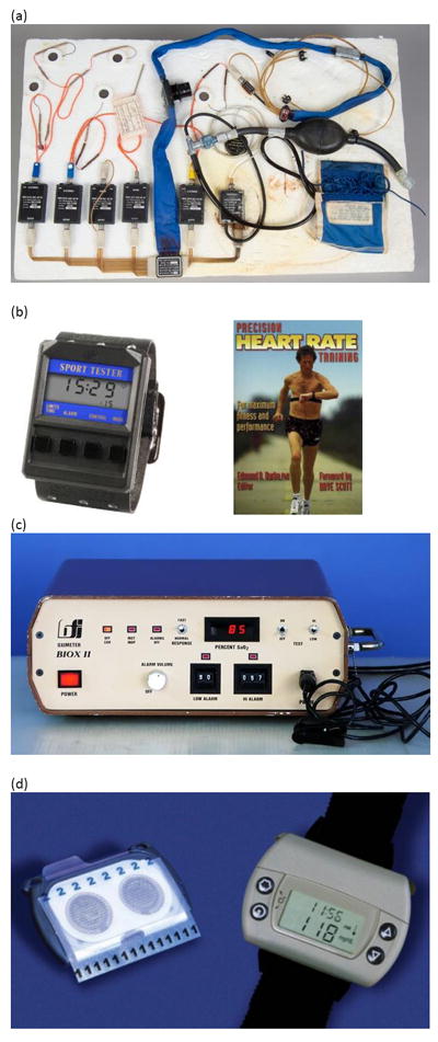
Historical examples of sensors including (a) wearable sensors for the Apollo Space Program2, (b) Polar’s ‘Sport Tester PE2000’ heart rate monitor, (c) pulse oximetry worn on the fingertip, and (d) non-invasive chemical glucose sensing with the GlucoWatch product3 (discontinued). The devices shown in (a) and the pulse-ox meter in (c) were wearable, but they were not wireless like the devices shown in (b) and (d).
Later, in the 1980’s, the general population began to experience the impact of wearable sensors. Wireless electrocardiogram (EKG) heart rate monitors were used in 1977 by the Finnish National Cross-Country Ski team, using a wearable form factor developed by Prof. Seppo Säynäjäkangas. Popularity of this wearable monitor grew to the point of introduction of commercial products by Polar Electro in the early 1980s. A watershed moment occurred in 1982 when Polar introduced the Sport Tester PE2000 (Figure 1b). Also in the 1980’s, Biox (Colorado USA) introduced the first commercial pulse oximeter. Within several years, pulse oximetry emerged as standard measurement during general anesthesia (Figure 1c).
Wearable chemical sensors took much longer to see a meaningful attempt at commercial introduction. For example, in 1962, Leland Clark and Ann Lyons from the Cincinnati Children’s Hospital developed the first glucose enzyme sensing electrode. It took much longer though, for a non-invasive wearable sensor to be attempted. A particularly important historical example is taught by examining the GlucoWatch product introduced by Cygnus in 2002 (Figure 1d). GlucoWatch was an impressive achievement in non-invasive biosensing of glucose for diabetes patients. The device utilized two gel pads on skin that were cycled with DC potential to extract, by reverse iontophoresis, both interstitial fluid and glucose in the interstitial fluid.3 The watch-like device utilized a current density of ~0.5 mA/cm2 to extract interstitial fluid through mainly pre-existing pathways in the stratum corneum (sweat ducts, hair follicles) at a rate of ~5 to 50 nL/min/cm2. Reverse iontophoresis generates an electro-osmotic flow of interstitial fluid through paracellular pathways, because plasma membranes are negatively charged which promotes a moving electro-osmotic sheath of Na ions. The DC potential was reversibly cycled every 10 minutes between the gel pads to prevent pH accumulation at the electrodes, which otherwise would harm the skin. The glucose was sensed using the well-known immobilized glucose-oxidase enzymatic electrode system. Cygnus secured FDA approval of the GlucoWatch for diabetes monitoring, which was quite an accomplishment given that the approach was non-invasive and that diabetes can be life-threating if glucose is not accurately monitored. However, GlucoWatch ultimately failed as product due to repeated need for calibration using traditional finger-prick methods, errors in readings if any sweating occurred, and in some cases an unusual tingling sensation or skin damage after multiple hours of reverse iontophoresis. Even today, non-invasive wearable chemical sensors do not yet exist as a widespread product (and as a reminder, although widely used, transcutaneous glucose monitors are not applicable in this review because they are invasive).3
Lastly, it is worth to briefly discuss wearable sensors as we know them today. Today’s wearable sensors are dominated by commercial wrist-watch sensors such as FitBit and Apple Watch, and medical patches such Medtronic’s SEEQ Cardiac monitoring system. It is important to note, that wearable sensors today are primarily simple electrical and optical measurements on skin, most of which having been available for decades. This is an excellent segue, as this review now shifts to discussing the opportunities and challenges as wearable sensors attempt to extract new types of information from the body.
The Epidermis as an Information Barrier
That the epidermis is an information barrier is hardly surprising, since it is the first line of defense in our immune system, and because it serves as barrier to loss of water and circulating nutrients and solutes in blood. The epidermis also protects underlying tissue from damaging ultra-violet light. Furthermore, the stratum corneum is dry and oily, and therefore electrically resistive. The epidermis is also soft, stretchy, and slides over underlying organs, dampening the effects of mechanical forces inside the body. For all these reasons and more, the epidermis generally is more of an information barrier than it is an information source when it comes to wearable sensing. In this section, we first describe the epidermal structure in detail, including sources of chemical contamination. We then examine the impedance and noise sources specific to mechanical, optical, and electrical sensing. Lastly, we should note that there are some applications where the epidermis is not a barrier (e.g. wound healing, transdermal needle-based glucose monitors). As noted previously, such technologies are not included in this review because they are at least partially invasive in nature (i.e. they require a non-natural opening through the skin).
Epidermal Structure
The epidermis is a stratified squamous epithelium with each of the strata serving an important role (Figure 2). The deepest layer, the stratum basale, forms a continuous sheet of cells (largely keratinocytes, but also melanocytes, Langerhans cells, Merkel cells) that separate the dermis from the epidermis. The highly proliferative keratinocytes in this layer divide and migrate upward to form the stratum spinosum. The keratinocytes of this layer actively synthesize fibrillar proteins that serve as the precursor to desmosomes, a type of cell-to-cell adhesion structure important for tissues to resist high shear stresses. These keratinocytes mature to form the stratum granulosum, which is responsible for inducing cell dehydration then cell death, cross-linking keratin fibers, and releasing lamellar bodies to form the intercellular hydrophobic barrier of the stratum corneum.4 The tight junctions between cells of the stratum granulosum further impede the flow of water and solutes between the viable epidermis and the stratum corneum. Some areas of thick skin possess a stratum lucidum, a region of several additional layers of keratinocytes found between the stratum granulosum and the stratum corneum. The stratum corneum is held together by corneodesmosomes. Proteases degrade these junctions and eventually cause the dead cells at the surface to shed in a process called desquamation. The tight junctions of the stratum granulosum and the organized intercellular lipid lamellae of the stratum corneum form the epidermal barrier.5 Skin appendages such as hair, sebaceous glands, and sweat glands provide a natural pathway through the stratum corneum barrier, but still have layers of surrounding live cells that separate the outside world from the inside of the body.
Figure 2.

Diagrammatic cross-section of human skin, including a zoomed in view of the epidermis. Adapted from Blausen 2014.189
Epithelia like the epidermis are common in other areas and organs of the body where a barrier function is required. The oral mucosa (mouth lining) is made up of both keratinized and non-keratinized stratified squamous epithelia. Keratinized regions are found in the masticatory mucosa where abrasion is common such as the surface of the tongue, hard palate, and gingiva. The lining mucosa is largely non-keratinized and lacks a stratum corneum. The corneal and conjunctiva epithelia of the eye are also examples of similar structures. However, the focus of our next discussion will be on the skin, because the skin is where most wearables currently interface with the body.
Chemical Impedance and Contamination
Chemical Impedance
As noted in the previous section, the skin is by design a barrier to transport of chemicals. The superficial layers of the epidermis, which include the tight junctions of the stratum granulosum and the interlamellar hydrophobic barrier of the stratum corneum are the major contributors to chemical impedance of the epidermis. Disrupting this epidermal barrier is possible, and has been extensively studied for transdermal drug delivery purposes. The barrier can be disrupted by mechanical methods such as microneedles6, tape-stripping which removes the stratum corneum7, sonophoresis8, electroporation and reverse iontophoresis9,10, and chemical methods such as permeability enhancers that increase paracellular pathways5. The effectiveness of all these methods, and/or determining the integrity of the epidermis, is often assessed by measuring a change in the transepidermal water loss (TEWL).11 Of these techniques, only the invasive methods that form an actual physical pore can allow access to analyte concentrations at their blood and interstitial fluid levels. For all non-invasive methods, even with skin-permeability enhancers, the chemical impedance of the skin remains very high.
Chemical Contamination
Not only does the skin serve as a barrier to analytes, but it can also contaminate analyte concentrations when collecting samples such as sweat, interstitial fluid, and blood. For example, estimates of the density of bacteria found on the skin are as high as 10 billion/cm2.12 Bacteria can consume analytes such as energy sources like glucose and secrete analytes such as proteins or cellular waste products. These alterations of levels of analytes by the microflora pose a challenge for chemical biosensing applications. In addition, sweat minerals have been shown to accumulate in the superficial layers of the epidermis and possibly in the sweat duct itself prior to sweating events.13 It can be assumed that similar accumulation may occur with other analytes, including proteins. For example, simply washing the skin surface does not mitigate contamination, as shown in Table 1 where even small analytes (calcium) to large analytes (proteins) exist at concentrations high enough cause significant errors in the concentrations measured in sweat.13 These contaminants also can cause significant errors for blood or interstitial fluid samples when the sample volume is very small and a needle is used to puncture the skin for fluid extraction. Finally, the skin surface is constantly being coated with proteases which aid in the shedding of dead skin cells and a mixture of triglycerides, wax esters, squalene, and metabolites from sebaceous glands.4,14
Table 1.
Evidence of contamination in initial sweat samples collected from skin into a bag with: true sweat level based on dripping sweat collection and an oil layer on skin to block contamination; dripping sweat collection without an oil layer on skin to block contamination; scraping sweat collection without an oil layer to block contamination. cAMP is cyclic adenosine monophosphate. Skin was washed/rinsed/dried before collection. Adapted.13,15
| Analyte | M.W. (Da) | Wash & true level | Wash & drip collect | Wash & scrape collect |
|---|---|---|---|---|
| calcium | 40 | ~0.25 mM | + 150% | + 500% |
| urea | 60 | ~4 mM | + 40% | + 150% |
| cAMP | 329 | ~0.2 nM | + 200% | + 650% |
| protein | 10’s k | ~25 mg/dL | + 60% | + 150% |
Chemical contamination does not always have to be a problem. For example, in non-invasive sweat sensing applications, epidermal contaminants can be avoided by preventing sweat from contacting the epidermis by coating the skin with an occluding layer of petroleum jelly or oil.13,15 Furthermore, with the growing awareness of the linkages between the microbiome and health status, measuring the microbe-induced concentrations of analytes on the skin could represent a significant opportunity in itself.12
Mechanical Impedance, Noise, Delamination, and Stretching
Mechanical Impedance
Due to the complex, highly anisotropic composition of the human skin, the skin produces a non-linear stress-strain curve when elongated. The collagen fibers present in the dermis align, resisting further deformation at around 30% strain. Silver et al. calculated Young’s moduli of 0.10 MPa rising up to 18.8 MPa at approximately 30% strain of human skin tested within 7 days of autopsy.16 The mechanical properties of skin are also orientation dependent defined by Langer lines, which are directions along which have the lowest elastic modulus on the human skin.17 The Young’s modulus (elasticity) of the human skin is also largely variable with age, hydration, and location on the human body.18-20
The human skin is also frequency dependent and can be modeled as springs, dampers, and masses. When the human skin is stimulated with a variable mechanical input, the mechanical impedance of the skin changes as a function of frequency. As the frequency of a normal force increases, the mechanical resistance (dampening component) of the skin increases and the elasticity (spring and mass component) of the skin becomes stiffer.21
In addition to normal forces, elastic wave propagation systems have been used to evaluate shear wave attenuation along the skin.22 At lower frequencies shear waves propagate along the surface of the human skin (stratum corneum), while at higher frequencies shear waves propagate through the bulk medium in the dermis containing mucopolysaccharide-water gel components.23 Shear wave propagation is transmitted via viscous coupling within the human skin medium. Therefore, water, which affects the viscosity of the stratum corneum, can directly affect the mechanical properties of the human skin within physiologically relevant frequencies.
Coupling to the Skin
To best match the skin’s modulus, silicone elastomers, such as polydimethylsiloxane (PDMS), have been used. PDMS is a common silicone elastomer with a Young’s modulus of ~3 MPa (Sylgard 184, 10:1)24, but is far too stiff in comparison to the human skin which can lead to delamination. Alternatively, softer materials such as silicone elastomer Ecoflex (Smooth-On) have been widely used due to its Young’s modulus (125 kPa) matching that closely to that of the human skin allowing for conformal contact to the human body.25-27
Mechanical Noise
The noise from wearable mechanical sensors can be classified into two categories: motion induced noise and sensor intrinsic noise. Motion induced noise is challenging for applying mechanical sensors in use cases, such as body movement during respiration rate measurement28-31, or bending effects during pressure measurements.32 These types of noise usually can be reduced by using a redundant sensor, while also applying algorithms to pick out the real signal from noise.28,33 Sensor intrinsic noise is also a challenge in wearable mechanical measurements such as temperature noise for resistive sensors25,34,35 and parasitic noise in capacitive sensors36-38
Stretching
Another challenge in fabricating robust mechanical sensors is designing materials to stretch. Any materials that are significantly thin inherently are able to withstand larger bending strains (ε = d/2r), but these materials cannot stretch, fracturing at tensile strains of ~1%.39-41 Research has shown that materials that are strained fail due to fracturing, slipping, or delamination of the thin film.42,43 These failure modes occur due to the weak adhesion between the thin film and substrate. Improving the adhesion of the thin film to the substrate has been found to significantly improve the mechanical robustness of thin films due to strain delocalization.41,44-48 Li et al. reported theoretical calculations illustrating the importance of interfacial strength between the thin film and substrate in strain delocalization.48,49 Their calculations have shown that interfacial strength helps metallic thin films deform uniformly over large tensile strains, whereas weaker interfacial strengths lead to necking at areas of metal debonding or slipping from the substrate.49 Improving the adhesion of the active sensing material to the substrate can then improve the robustness and reliability of the mechanical sensor.
Electrical Impedance and Noise
Electrical Impedance
Skin-interfaced electrodes in wearable sensors transduce naturally occurring, time dependent ionic flows in the human body to measurable electrical signals; alternatively, as actuators such as nerve stimulation, they stimulate changes in these flows. The quality of recordings and the efficiency of stimulation largely depend on the electrical impedance of the electrode-skin-body interface. The best interface typically consists of a ‘wet’ electrode contact, typically achieved by a hydrogel or electrically conductive adhesive, both containing electrolytes. Prolonged use of wet electrodes will also hydrate the skin, reducing its electrical impedance. Without a wet contact (i.e. a dry electrode) the roughness of skin introduces pockets of air that can result in a higher electrical impedance. The electrical impedance of skin with a dry electrode can therefore vary greatly with even slight changes in the pressure of electrode contact. We will continue our discussion assuming a good ‘wet electrode’ contact to the upper surface of the skin. In this case, the electrical impedance is limited to the skin itself and the underlying body.
This electrical impedance of the skin can be approximated using equivalent circuit models that consist of parallel and series combinations of resistors (R) and capacitors (C) (Figure 3).50,51 These models attempt to capture the effective behaviors of the complex structures and properties of the various layers of the skin and its contact with the electrodes. The top layer of the skin, known as the epidermis, plays the most important role in this context. The construction involves multiple sublayers, depending on the location across the body, and each of these evolves continuously with time.52 The topmost layer, the stratum corneum consists of flattened, stacked non-nucleated dead cells (corneocytes) and intercellular lipids, with a thickness (10 -100 μm) that varies with the number of corneocyte layers (15-20 layers on most body sites) and the state of hydration.52-55 The stratum corneum is electrically insulating, with a resistance that is significantly higher than that of the underlying layers of the epidermis. The resistance and capacitance of the stratum corneum are in the range of ~105 Ω cm2 and ~30 nF/cm2.51,56,57 This capacitance is easily calculated assuming a thickness of 15-20 μm and a dielectric constant of ~ 15-20.55For measurement frequencies between 1 Hz to 10 kHz, the stratum corneum dominates the overall impedance of the electrode/skin contact. This impedance can vary strongly depending on the activity and density of sweat glands which can form a path of ionic conduction, and on the local thickness and composition of the stratum corneum.51,57-59
Figure 3.
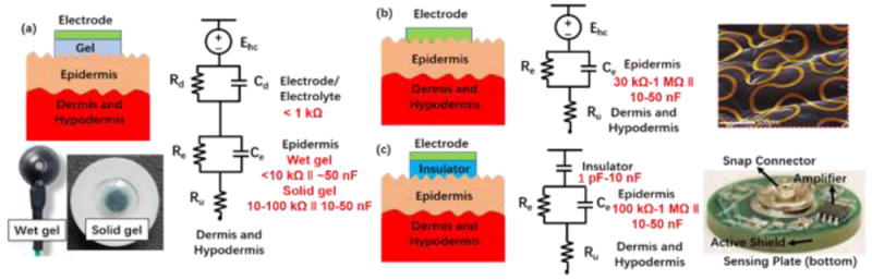
Equivalent circuit models of electrode-skin interfaces for different electrode designs. (a) Gel electrodes, including wet and solid forms (Disposable Deep EEG Cup Electrode, Rhythmlink; ECG Electrode H1354LG, Kendall). (b) Dry contact electrodes.61 (c) Dry capacitive (non-contact) electrodes.51
Using a series of parallel RC-circuit models, the impedance of each skin layer, including epidermis, dermis and hypodermis, can be approximated as a complex expression Z (ω) = R/(1 + jωCR), where R and C are the resistance and capacitance of the skin layer, ω is angular frequency, and j is the imaginary unit. The entire epidermis, including the SC, can be treated equivalently with a resistance Re and capacitance Ce which is chosen according to the body location and the presence of electrodes (discussed in the next paragraph). The underlying dermis and hypodermis layers are significantly more conductive than the epidermis, such that their capacitance can be neglected and the impedance can be treated as purely resistive (Ru). The mode of electrode contact must be considered as well, including any contact potential that might result from metal contact. Figure 3 summarizes and compares the impedance of the electrode/epidermis interface and the entire system for various types of electrodes.
Our discussion will now return to dry electrodes. Dry electrodes eliminate the electrolyte materials entirely, and rely instead on direct contact with the skin. The formats range from flat metal pads to open network mesh structures to soft conductive composites. Although such electrodes do not offer direct skin-hydrating effects, they can trap some moisture from natural transepidermal water loss and/or sweating. The impedance depends on these effects and on the contact quality of electrodes on the skin. As reported in the literature, in the presence of dry electrodes, resistance Re ranges from 30 kΩ cm2 to 1 MΩ cm2 and the capacitance Ce ranges from 10 nF/cm2 to 50 nF/cm2.60,61 In extreme cases, a parallel RC circuit representing the electrode-electrolyte interface that results from trapped moisture can be added in series, similar to the case of wet electrodes. Additional detailed discussion on advanced dry-electrode formats is reserved for the Wearable Electrical Sensors subsection.
Electrical Noise
Electrical noises affecting the signal quality and statistical power of wearable electrophysiological recordings mainly include intrinsic body noise, skin-electrode interface noise and environment noise.50,62,63 Body noise is unavoidable and not dominating in most cases, including undesirable eye movements, muscle activity, cardiovascular activity and skin potentials. This type of noise can be largely lessened with data processing techniques. Skin-electrode interface noise contributes to a significant part of the signal noises for various electrodes as discussed above. Motion artifacts often arise from the interface due to relative motion of electrodes to the skin. Wearable systems with robust mechanical attachment of electrodes on the body can be designed to decrease these motion artifacts. Environment noises come from 50/60 Hz powerline interference, electromagnetic interference from surrounding electronics and moving electric charges in the recording environment. The implementation of a buffer at the electrode sites, shielding electrodes and cables, and driven right leg circuits can effectively reduce these interference noises.
Optical Impedance and Noise
Optical measurements performed through the skin offer noninvasive, contactless modes for acquiring essential information of relevance to physiological health. In some cases the skin offers a passive window as an optical interface to underlying vascular structure and organ systems; in others, the optical properties of the skin itself are important.64
Optical Impedance
Transmission, absorption and scattering properties associated with the human skin can be considered by dividing the system into three layers of distinct tissue types and their optical characteristics65 (Figure 4): (1) the stratum corneum a thin layer which predominantly consists of dead squamous cells, which are highly keratinized,66 (2) the underlying epidermis, which contains skin pigmentation comprised of mainly melanin which absorbs shorter wavelengths such as UV, and visible light is also absorbed to some extent. (3) The dermis, which is highly vascularized and contains absorbers in the visible spectral range, including blood hemoglobin, carotene and bilirubin67. Visible light attenuation is also dominantly determined by the dermis because it is thicker than the layers above it.
Figure 4.
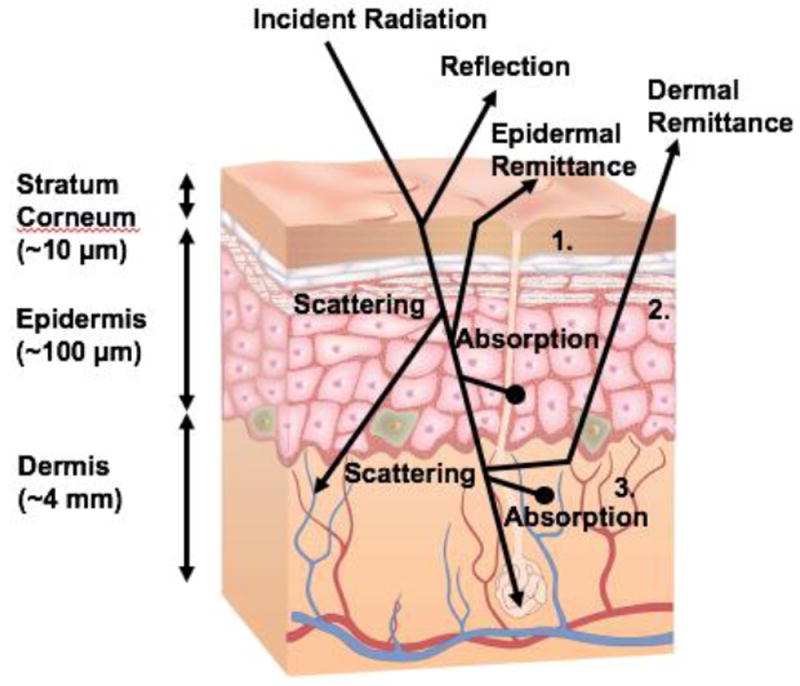
Schematic diagram of optical pathways in skin. Species largely responsible for absorption and scattering in the skin are:keratinized squamous cells (1) and large melanin aggregates (2). The vascularized dermis (3) includes absorbers such as oxygenated and deoxygenated hemoglobin, carotene and bilirubin. Scattering occurs on collagen fibrils and bundles.
The optical characteristics of the stratum corneum are mainly defined by its rough surface which results in non-specular (diffuse) reflection. Interfacial Fresnel reflection due to the refractive index (nd) mismatch of air (nd=1) and the stratum corneum (nd~1.55) at this layer is typically 4-7% for normal incident light68. Part of the incoming radiation undergoes diffuse forward scattering within this layer, thereby causing collimated light to diffuse65. The scattering characteristics of the epidermis follow from interactions with large melanin aggregates, known as melanosomes (>300 nm in diameter) which exhibit mainly forward scattering, and with melanin particles (30–300 nm in diameter), which create Mie scattering. Scattering in the dermal layers result from collagen fibrils and bundles (1-8μm)69 that create a combination of Mie and Rayleigh scattering69. Overall scattering of the skin is dominated by the dermis partly because its thickness (~4 mm) is much larger than that of the epidermis (~100 μm) and the stratum corneum (~10 μm). For some surfaces, like the palmer surface of the hand, the stratum corneum can be much thicker and become more dominant in the optical impedance (e.g. an extreme example, being calluses on the hand).
The skin can also serve as a window to investigate the health of underlying organs. One such approach, known as functional near infrared spectroscopy (fNIRS)70, allows for spatial resolved observations of oxygenation changes in the brain. Techniques such as diffuse optical tomography allows for insight in tissue health and is an effective tool for breast cancer detection.
Optical Noise
Optical noise sources interfering with the signal acquisition can be classified into two categories, environmental noise and motion artefacts. Environmental noise such as ambient and natural light can emit slow light transients such as variations in day or room light or high frequency noise such as pulse width modulated or fluorescent artificial light sources71. These environmental noise sources are less significant due to the high absorption of the skin and generally low light intensity of the parasitic light in comparison to the measured signal. Environmental noise is also eliminated easily by covering the sensing area with an opaque material. Motion artefacts however, which are induced by relative motion to the sensor is the primary source of noise that presents a major challenge in many measurement techniques72,73.
Wearable Sensors
We will now discuss mechanical, electrical, optical, and then chemical sensors. For each sensing modality, we will first discuss the basic body-to-signal transduction method. Next, actual devices and demonstrations will be reviewed. Lastly, we will briefly touch on unmet challenges and outlook, which should help those new to the field determine what innovations they could contribute.
Wearable Mechanical Sensors
In this section, four classes of mechanical sensors will be discussed: piezoresistive, capacitive, iontronic, and piezoelectric. Within each class of mechanical sensors, different mechanical modalities will be discussed individually.
1. Piezoresistive Sensors
Resistive Strain Sensors: Body-to-Signal Transduction
When conductive materials are subjected to mechanical deformation, their electrical properties change. This electromechanical response is known as the piezoresistive effect as seen in Figure 5. Due to the Poisson ratio (v), materials that are elongated also contract in the transverse direction of elongation. Consequently, the resistance R of a conductive material will change as shown by the following equation:
where ρ is resistivity, L is the length, and A is the cross-sectional area of the conductor. The piezoresistive effect has been widely used in wearable electronics for the detection of human physiological movement due to its simple readout, high sensitivities, and simple device designs.74-76
Figure 5.
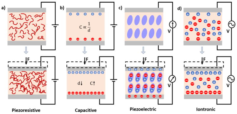
Schematics illustrating the different modalities of mechanical sensors. a) Piezoresistivity b) Capacitance c) Piezoelectricity190 d) Iontronic.
Resistive Strain Sensors: Devices and Demonstrations
A wearable resistive strain sensor must meet certain criteria including high stretchability and flexibility, low hysteresis, and high sensitivity. A device that is able to stretch and flex will be mechanically reliable when mounted on the body allowing for long-term use. A wearable strain sensor ideally will also not exhibit extensive plastic deformation when subjected to repeated strain. Most importantly, strain sensors must exhibit high sensitivity to strain to improve signal acquisition and detections of dynamic strain. The strain sensitivity is typically characterized with gauge factor (GF):
where ΔR is the change in resistance, Ro is the unstrained resistance, and ε is strain.
A typical stretchable strain sensor consists of a thin film conductor on a silicone elastomer (i.e PDMS). When these conductors are stretched, the geometrical change induces a change in electrical resistivity. Therefore, it is possible to mount these strain sensors on the human body to detect and quantify motion, such as the bending of a finger, elbow, or knee.
In addition to simple geometrical change in resistance, microcracking of the conductor has shown to contribute to even higher GFs.77,78 For example, Kang et al. reported nanoscale crack junctions in Pt thin films inspired by the crack-shaped slit sensory organs of spiders as shown in Figure 6.77 When strained, the microcrack junctions become larger thereby increasing the electrical resistance of the sensor. These nanoscale crack junctions were achieved by bending Pt thin films over a set curvature. Using this controlled cracking strain sensor, a GF of 2000 (450-fold increase in GF at 0.5% strain) over a range of 0-2% was achieved allowing detections of physiological signals such as speech patterns and heart rate. However, the durability and stretchability was limited, showing signal degradation at about 500 cycles of 2% strain.
Figure 6.
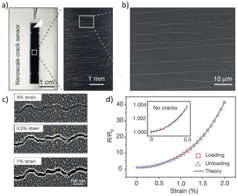
a) Platinum thin film strain sensor using microcracking strategy. b) Scanning electron image (SEM) illustrating the microcrack junctions within the Platinum film. c) SEM image of the microcrack junctions at various strains. d) Electrical resistance change in response to strain.77
Microcracked strain sensors exhibit high GFs but are not able to withstand large amounts of strains. To address this issue, high aspect ratio nanomaterials, such as carbon nanotubes (CNTs), have been used to greatly improve stretchability. During high strains, each individual nanoparticles remain in contact due to their high aspect ratio.79 For example, CNTs spray deposited onto a silicone elastomer could achieve strains of up to 500% with a measured GF of 1.75.25 Silver nanowires (AgNWs) have also been shown to withstand strains of up to 70% with a range of GF’s from 2-14.80 It is also possible to incorporate buckled structures within CNT thin films to greatly improve stretchability of up to 750% strain, but exhibiting a lower GF of 0.65.27
Resistive Strain: Unmet Challenges and Outlook
In general, to fabricate highly sensitive strain sensors, stretchability is typically compromised. Conversely, highly stretchable strain sensors are generally characterized with low GFs, or strain sensitivities. In addition, stretchable strain sensors suffer from hysteresis due to the viscoelastic properties of silicone elastomeric substrates. Pegan et al. have shown that wrinkled microstructures in platinum thin films were able to achieve GFs of 42 while still being able to elongate up to 185% strain using a shrinking fabrication process.81 Correlation with spirometry data and the wrinkled stretchable strain sensors were made as shown in Figure 7. Although high GFs and stretchability were achieved, hysteresis could not be eliminated rendering high frequency dynamic measurements difficult.
Figure 7.
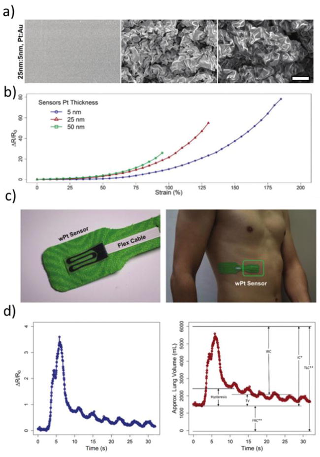
a) SEM images of the processing of a Pt:Au thin film using a shrinking fabrication process: Deposition, shrinking, and then transferring to a silicone elastomer from left to right. Scale bar is 5 μm. b) Strain sensitivity curves of different thickness of Pt wrinkled thin films. c) Wrinkled Pt thin films were put in adhesive and mounted onto the body to detect respiration. d) Electrical resistance response to chest wall expansion during respiration is shown on the left. Right graph shows correlated lung volumes using spirometric and strain sensor data.81
Resistive Pressure: Body-to-Signal Transduction
Piezoresistive sensors can also be designed to detect subtle pressures such as pulsatile blood flow or ‘touch’. Unlike strain sensors, piezoresistive pressure sensors are typically comprised of two contacting electrodes with a nominal resistivity. This nominal resistivity can then be modulated by increasing or decreasing the number of electrical contact points between the electrodes by applying pressure. The pressure sensitivity (PS) can then be defined as
where R is resistance, Ro is the initial resistance, and P is pressure. As with strain sensors, an ideal pressure sensor would be highly flexible, exhibit low hysteresis, and have high pressure sensitivities. Strategies to improve mechanical compliance are similar to that as discussed before with strain sensors.
Resistive Pressure: Devices and Demonstrations
To improve the sensitivity of piezoresistive pressure sensors, structural surface modification of the electrodes is necessary. Incorporation of nano/micro-scaled structures can provide large changes in contact resistance allowing for detections of smaller pressures. For example, Yao et al. demonstrated that a fractured micro-structure graphene coated polyurethane sponge produces a two-order of magnitude increase in sensitivity within the 0-2 kPa regime in comparison to a sensor with no fractures.82 Dynamic bridging of AgNWs and graphene oxide allowed for pressure sensitivities of up to 5.8 kPa-1.83 The fracturing provides an increasing amount of electrical contact points when pressure is applied allowing for higher pressure sensitivities. Similarly, Pan et al. achieved pressure sensitivities of 133.1 kPa-1 using elastic microstructured films prepared from a polypyrrole hydrogel allowing for detections of less than 1 Pa as seen in Figure 8.84
Figure 8.
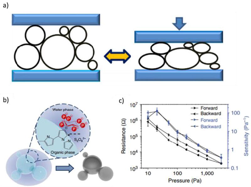
a) Schematic illustration of the elasticity of hollow sphere structured polypyrrole (PPy). b) Schematic illustration of the phase separation between water and organic components for the synthesis of PPy hydrogels. c) Electrical resistance response to induced pressure.84
Resistive Pressure: Unmet Challenges and Outlook
Although characterized with high pressure sensitivities, piezoresistive pressure sensors are typically fabricated using thick PDMS substrates which poses limitations in wearable applications. In addition, piezoresistive sensors still require an external power source for continuous monitoring applications. Current available wearable piezoresistive strain sensors include Velostat, a flexible conductive polymer impregnated with carbon black, and conductive rubbers from Adafruit. However, these products lack stretchability (maximum of 70% strain), conformality to the human body, and high strain sensitivities (GF = 1). Velostat has a response that is sensitive to changes in temperature and its performance suffers from effects of viscoelastic creep.85 Therefore, further research is needed in achieving commercially available highly stretchable, sensitive, and robust sensors for wearable applications. Addressing these issues could provide steps toward an ideal continuous wearable monitoring system using piezoresistive sensors.
2. Capacitive Sensors
Capacitive: Body-to-Signal Transduction
Capacitive sensors are a highly attractive sensing mechanism for mechanical stimuli, as they have gained popularity in consumer electronic touch-screens with good device sensitivity, low power consumption, and adaptive sensing configurations.36,86-94 Parallel-plate configuration is the most popular architecture adapted in the mainstream capacitive sensor designs as it is easy to construct and straightforward to model. The capacitive change is governed by the classic equation of
in which ε is the permittivity of the cavity between two plates, A and d represent the overlap area and the distance between two plates, respectively. As the distance, area, or permittivity is altered by the external loads, it leads to the change of capacitive readouts36,86-94, which can be measured either as a passive capacitor36,86-91 or through modifying the response curve of an active component, such as field-effect transistors (FET)92-94.
Capacitive: Devices and Demonstrations
Capacitive pressure sensors have been largely employed in consumer electronics and industrial applications, and more recently, with emerging wearable trends, they extend their applications to various human-pressure sensing interfaces, including electronic skin mimicking tactile sensation79,92,95,96, body pressure mapping36,89, joint bending detection36,88. As the key element of a capacitive sensor, new electrode materials have always been a subject of interest to improve the flexibility and stretchability.36,79,97 Example electrode materials include conductive nanostrcutures36,79 and polymeric conductors94. In addition, modified sensing structures and interfaces have been explored to further increase the device sensitivity.90,94 Bao’s group introduced a series of capacitive wearable sensors.79,91,92 In 2011 they introduced a flexible capacitive pressure and strain sensing array based on carbon nanotubes coated polymer film where pressure and strain can be measured in a transparent and flexible package (Figure 9a).79 Then, a microstructure patterned elastic layer was been introduced to the capacitive pressure sensor, creating the electrical response of a thin-film FET (Figure 9b).90,92 Human radial artery pulse waves could be captured by this device, benefitting from its high sensitivity (Figure 9c).92
Figure 9.
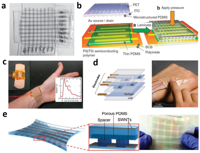
(a) photo of pressure and strain sensors based on transparent elastic films of carbon nanotubes. (b) Microstructured pressure sensor array. (c) Pulse pressure signal were obtained by attaching the pressure sensor to the wrist of a test person (d) The ionic gel based sensor array structure and when attached on the back of a hand. (e). Schematic and photo illustration of the energy harvesting e-skin.
Besides pressure, other sensing modalities, such as stretch and bending, have also been achieved with capacitive sensors. Suo’s group synthesized highly stretchable biocompatible ionic hydrogel films98 to function as the electrode plates of a parallel plate capacitor (Figure 9d).97 The ionic conductor/dielectric/ionic conductor hybrid structure can measure pressure and stretch by attaching its ultraflexible, stretchable and transparent sensing film on human skin.97 A recent effort by Bao’s group has led to a multifunction wearable sensor that can differentiate pressure, stretch and bending, and provide energy harvesting function, all in a multilayer porous polymer/single-walled nanotubes structure (Figure 9e).91
Capacitive: Unmet Challenges and Outlook
Currently, parallel plate capacitive sensors dominate the commercial flexible pressure sensor market, such as Pressure Profile Systems, Inc. (PPS) flexible tactile sensation99 and body pressure mapping100 systems. Although the parallel plate capacitive sensors suffer from parasitic noises from the body and from the environment, particularly in wearable applications, they offer high sensitivity, low power consumption and FET integratability in comparison with other sensing modalities.
3. Iontronic Sensors
Iontronic: Body-to-Signal Transduction
To tackle the challenges of the high sensitivity and low parasitic noise, a new iontronic interface sensing mechanism has been introduced with significant improvements on device sensitivity and signal to noise ratio. Electrical double-layer (EDL) based supercapacitors have long been used in energy storage devices, relying on very high surface areas that provide high energy density in small package. The EDL supercapacitor exists at the nanoscale interface between the electrode and the electrolyte. When utilized in flexible mechanical sensors, it enables a high surface area and electrical capacitance that is at least 1,000 times higher than similarly sized traditional parallel plate capacitive sensors. This sensing mechanism enables greater immunity to environmental or body capacitive noises (can be hundreds of pF87), which is of importance for wearable applications. By integrating with ionic materials, such as ion gels and ionic liquids, electrical double-layer (EDL) based capacitive sensing devices have been studied for wearable sensing applications.101-106
Iontronic: Devices and Demonstrations
An EDL-based pressure sensor was first reported using an electrolytic sensing droplet sealed in a polymeric package. This iontronic interface droplet sensing concept was later implemented in a matrix format for flexible pressure mapping and radial arterial waveform monitoring (Figure 10a,b).102 Furthermore, ionic gel has been introduced to this EDL sensing mechanism to achieve pressure measurement using a package made entirely of soft materials.106 The ultrahigh pressure-to-sensitivity of this device (3.1 nF/kPa) not only enabled it to measure subtle body interface pressure changes such as radial arterial pulse waveform measurement, but also detected pressure variation in a high capacitive noise environment (under water) (Figure 10c,d). In a medical application where interface pressure for chronic venous disorder compression therapy is to be measured, the EDL-based iontronic pressure sensor array has been introduced to determine pressure distribution for real-time measurement in a wearable health monitoring device construct (Figure 10e).105
Figure 10.
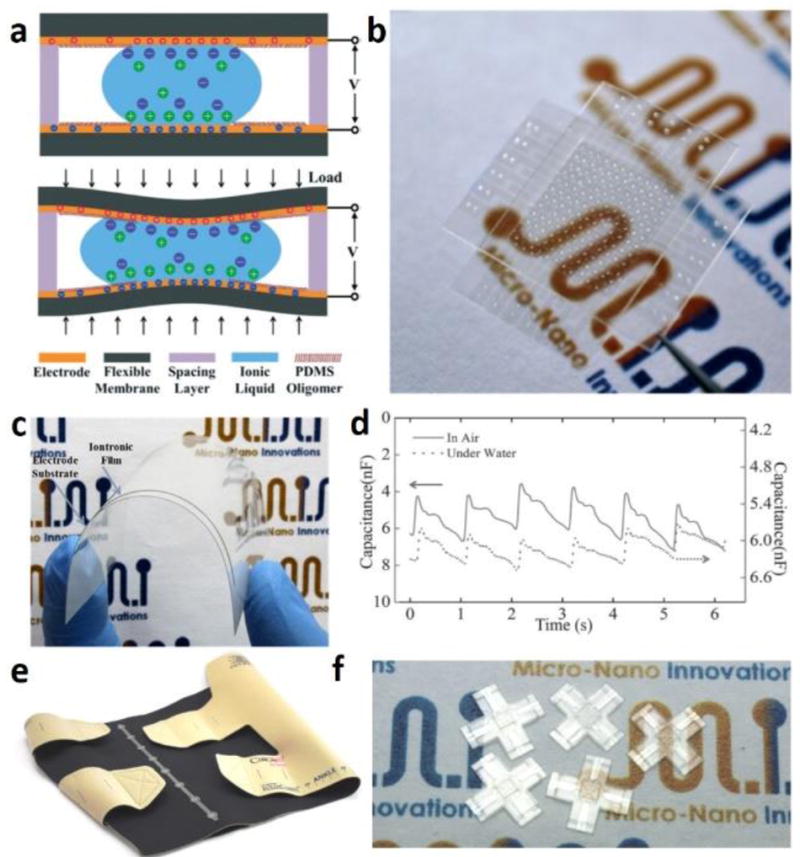
(a) Iontronic droplet sensor operation principle. (b) Photo of an iontronic microdroplet sensing array. (c) Photo of a flexible ionic gel film on electrode substrate. (d) Real-time pulse pressure waveforms in the dry and underwater environments. (e) Photo of a commercial inelastic legging integrated with the iontronic flexible sensing array. (f) Prototypes of the microfluidic tactile sensors for three-dimensional force measurements.
Besides pressure measurement, Ionic liquid has also been employed as EDL capacitive sensing element to resolve three-dimensional contact forces in a flexible and transparent microfluidic package for reconstructing finger tactile sensation.101 Benefiting from the highly sensitive and adaptive EDL capacitive sensing principle, 29.8 nF/N sensitivity can be achieved in 5 mm by 5 mm compact microfluidic package (Figure 10f).
Iontronic: Unmet Challenges and Outlook
Since the iontronic sensors are only a recently discovered technology, integrating this technology with industrial mass manufacturing is an unresolved challenge. Furthermore, when utilized for body-wearable applications, material toxicity must be considered as ionic materials sometimes have bio-compatibility issues when in contact with the body.
4. Piezoelectric Sensors
Piezoelectric: Body-to-Signal Transduction
The sensing mechanism for the piezoelectrical sensor is based on the piezoelectric effect of the materials that generate electrical charges under external mechanical force, pressure, or strain.107-110 When a mechanical stress is applied to a piezo-electric material, there is a change in electrical polarization inside the material (e.g. reconfiguration of the dipole-inducing surrounding, or by re-orientation of molecular dipole moments). This change in polarization results in a change in surface charge (voltage) at the surface of the piezoelectric material. The piezoelectric material usually used in wearable applications are PZT107,108,111, ZnO nanowires112, and P(VDF-TrFE)109,110,113.
Piezoelectric: Devices and Demonstrations
Applications of this technology include skin-mounted sensors for tactile sensation109, finger bending motion detection107,108, measuring arterial pulse pressure waveform108, detecting body movements108,113, and biomechanics characterization111. A tattoo-like PZT pressure sensor has been introduced by the Rogers group for vital signs monitoring. A device with a sensitivity of 0.005 Pa and mechanical response time of 0.1ms was achieved in a 25 μm-thick package (Figure 11a).108 Later in clinical setting, this piezoelectric device has been configured into biomechanics characterization tools to detect soft tissue viscoelasticity (Figure 11b).111 The device has been conformably contacted with textured skin and organ surfaces to conduct the measurement under quasi-static and dynamic conditions.108
Figure 11.
(a) photograph of the piezoelectrical pressure sensor wrapped on a cylindrical glass support and laminated on a wrist. (b) Photographs of a piezoelectric device fully laminated on the skin and its SEM image on artificial skin sample for tissue viscoelasticity measurement.
Piezoelectric: Unmet Challenges and Outlook
Commercial products such as piezoelectric film sensors have become available from multiple vendors. As an example, piezorelectric sensors are used in the sleep monitoring bands (Beddit114). The main disadvantage of these sensors is the charge leaking nature of the material which makes it difficult or impossible to detect stationary or low frequency mechanical stimuli. However, the high sensitivity and fast response time of the piezoelectrical sensors are still useful for detection of vibrations or dynamic pressure changes. Piezoelectric mechanical sensors also have the potential of achieving self-powered detection in wearable applications.115
Wearable Electrical Sensors
Electrical Sensors: Body-to-Signal Transduction
Electrical sensors measure a change in electrical resistance of the skin, or measure changes in capacitive or conductively coupled charge at the skin surface. In most cases, high-input-impedance electronics are used to detect these very small changes in charge. That leaves one major challenge for the body-to-signal transduction: good electrical contact with skin. There are two types of electrical contacts, wet electrodes, and dry electrodes. Wet electrodes combine a solid conductive pad interfaced to the skin via an electrolyte gel that minimizes the impedance of skin by: (1) hydrating it; (2) forming a conformal electrical contact with its textured surface (Figure 3). Dry electrodes eliminate the electrolyte materials entirely, and rely instead on direct contact with the skin. Further details on the electrical coupling (impedance) of wet electrodes and of dry electrodes was previously discussed in the Electrical Impedance and Noise sections of this review.
Electrical Sensors: Devices and Demonstrations
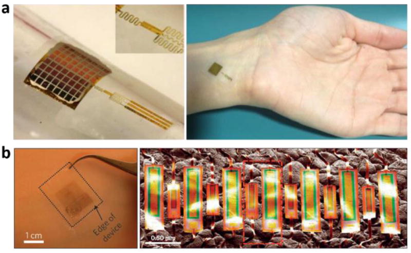
Many wearable sensing devices require repeated placement and removal of the device, prolonged use, and/or other factors that may not permit use of a wet-electrode format. Therefore, this sub-section begins with a detailed discussion on optimized dry-electrode configurations. Optimized dry-electrode interfaces minimize air gaps between the electrodes and the skin, and eliminate artifacts associated with relative motions between the electrodes and skin. Some of the most successful designs involve electrodes in ultrathin, low-modulus, stretchable configurations.116 The image in Figure 3b highlights the degree of conformality that is possible with a filamentary open mesh type electrode.61 In these designs, inert, bio-compatible metals such as gold minimize any chemical reactions with biofluids and/or immune reactions by the skin itself. Layout possibilities range from simple periodic serpentine geometries to fractal designs with enhanced stretchability and with orientationally and spatially tailored responses.117 A rich range of available fractal motifs can serve as space-filling structures with generalizable design rules. Fig. 12f shows devices in mesh architectures conformally mounted on the skin.118 Mechanical simulations in these and related geometries show that appropriate layouts can ensure that the strains in the metals remain well below their elastic limit. Optimized designs enable measurements of biopotentials with clinically relevant quality.119 One disadvantage is that the open mesh geometry reduces the area of the contact between the conducting parts of the electrode and the skin, thereby increasing the resistance and decreasing the capacitance of the interface. Composites that consist of soft silicone matrices and electrically conductive dopants, such as carbon nanotubes, graphene or carbon black, represent alternatives that improve the area coverage (Figure 12g-j).120,121 For long term use, dry electrodes must be constructed in a manner that allows some degree of transepidermal water loss and minimal thermal load, either through the use of thin backing materials that themselves are water permeable or through the introduction of physical microperforations.
Figure 12.
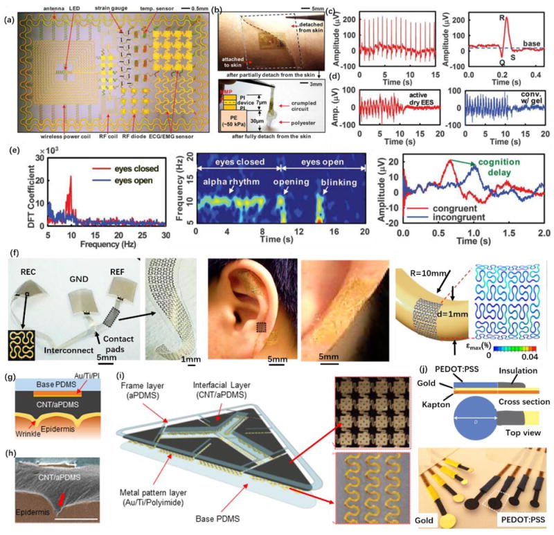
Demonstration of dry epidermal electrodes. (a) An electronics platform with multifunctionality and matched physical properties to skin.116 (b) The device conformally attached to the skin through van der Waals forces with negligible mass or mechanical loading on the skin. (c) ECG signals measured with an active epidermal electronic device shown in (b), showing a clear physiological signal corresponding to a single heartbeat (right) and (d) EMG measurements showing the comparison with that collected using conventional gel electrodes. (e) EEG measurements using a passive electronic device, including discrete Fourier transform coefficient of EEG alpha rhythms at ~10 Hz (left), the spectrogram of the alpha rhythm corresponding to the eyes close and open, and demonstration of Stroop effects in EEG. (f) Epidermal electronics with fractal architectures, showing devices laminated on the auricle and mastoid and finite element method analysis on the device with simultaneous bending along two orthogonal axes.118 (g) Conformal contact of carbon nanotubes (CNT)/PDMS adhesives with the textured skin surface, confirmed by a SEM cross-sectional image (h).120 (i) Structure of an ECG electrode composed of a CNT/PDMS interfacial layer and serpentine interconnect metal wires. (j) Schematic and photograph of dry electrodes with PEDOT:PSS coatings.121
Another type of dry electrode involves a purely capacitive interface, sometimes referred as noncontact dry electrodes. In the equivalent circuit for this case, an insulating layer that separates the surface of the skin from the conducting electrodes, can be approximated as a capacitor (Figure 3c). The interface can be described by a series connection of the capacitor with a parallel arrangement of resistance Re (100 kΩ cm2-1 MΩ cm2) and capacitance Ce (10-50nF/cm2).58,60 In most cases, the capacitance of the insulating layer (1 pF -10 nF) dominates the interface impedance.51 The nature of this electrical coupling leads to high levels of sensitivity to motion artifacts and time-dependent stray charges, thereby typically demanding the need for actively shielded amplifiers, as shown in Figure 3c. Capacitive electrodes eliminate irritation and allergic reactions that can sometimes be caused by the presence of electrolyte gels or by the direct contact of metal electrodes, and they also prevent exposure to leakage currents or electrical shorts. Under ideal testing conditions, the signal quality with such setups can approach those of standard wet electrodes, but in wearable applications, the artifacts can be prohibitive. It is worth noting that epidermal mesh electrodes can also be designed for capacitive sensing by fully encapsulating them with an insulating layer. Here, acquired electrophysiological signals can be less susceptible to motion artifacts associated with the coupling capacitance compared to conventional flat, rigid electrodes.61,122
Our discussion next turns to device demonstrations of wearable electrical sensors (Figure 12). Wearable systems with electrical interfaces to the skin allow high fidelity measurements of a broad range of physiologically relevant biopotentials, from electrocardiogram (ECG or EKG), electroencephalogram (EEG), electromyogram (EMG), electrooculogram (EOG), electroretinogram (ERG), galvanic skin response (GSR, also known as skin impedance or electrodermal activity (EDA)), to electrical impedance tomograph (EIT).50,51,58,59,123-125 Advanced technologies allow simultaneous measurement and analysis in several of these modes, at a single location with a single device or in multiple, time-synchronized positions across the body. The data typically consists of electrical potential, impedance and/or resistance. Dry electrodes are generally preferred due to their ability to operate stably for extended periods (days to weeks) without signal degradation and without causing discomfort. Here, the main limiting factor is the process of natural exfoliation of dead cells from the SC, such that accumulation to sufficiently high densities can degrade the electrical and mechanical properties of the interface. As discussed in the previous sections, dry electrode designs and supporting electronics must be considered carefully to enable high quality signal acquisition.51 Open mesh electrodes supported by ultrathin, low modulus elastomers offer excellent conformality to the skin and robust adhesion, with interface impedances in the range of a few tens of kΩ over frequency ranges relevant for most biopotential measurements, comparable with that achievable with solid gel electrodes.61 These designs can also incorporate capacitive coupling as outlined in the previous paragraph, but without any motion artifacts, due to the nature of the conformal contacts. In both cases, devices that use such electrodes can capture high fidelity electrophysiological recordings, including ECG, EEG, and EMG, without signal degradation and adverse effects on the subjects for up to two weeks, across bandwidth of 0.3 Hz-2 kHz. In some practical scenarios, noise induced by electromagnetic interference, triboelectric charging and other sources must be considered. A drive right leg (DRL) circuit can minimize the common-mode noise and amplifiers near the sensing site, and can lessen the differential input of common-mode noise. Shielding of the lead wires can also effectively reduce the noise from stray external electric fields.
Materials, mechanics designs and device structures now exist to allow such supporting electronics to be built directly into the same ultrathin, soft platforms as the conformal dry electrodes (Figure 12).61,116 An ideal is for the overall physical characteristics of these systems to match those of the epidermis itself, to enable robust, high quality interfaces without discomfort or irritation at the skin surface (Figure 12b). Representative electrical measurements, including EEGs, ECGs and EMGs, appear in Figure 12c-12e. The ECG data provides clear information on the depolarization of the right and left ventricles of the human heart, with quantitative correlation to clinical standards. EMG recordings show signal to noise ratios comparable to those of data obtained using conventional gel electrodes (Figure 12d). Similarly, high-quality EEG measurements of alpha rhythms are also possible (Figure 12e), where Peano fractal mesh electrodes enable integration on the highly irregular and textured surfaces on the auricle and the mastoid for up to two weeks (Figure 12f). Similar electrode interfaces can also be used to perform bioimpedance measurements, for determination of skin hydration at uniform or variable skin depth.126 In these measurements, the differential impedance collected from individual isolated capacitive electrodes directly correlates to the skin hydration level due to the electrical contributions of water in the skin. Multiplexed measurements from arrays of electrodes yield spatial maps of hydration, with quantitative accuracy as determined through comparisons to non-wearable hydration sensors.
Soft microfluidic enclosures capture some of the same advantageous mechanical properties of these systems, but in a manner that is compatible with standard, chip scale components.127 Such soft, stretchable electronic platforms integrate high-modulus, rigid, state-of-the-art functional components and a free-floating highly stretchable interconnect network in a thin elastomeric microfluidic enclosure that supports sensors, radios, circuits, and power supply components, with a wireless operational mode. These systems allow not only electrophysiological sensing, including precision measurements of ECG, EMG, EOG, EEG, but also motion recording with a triaxial accelerometer and temperature measurement with a thermal sensor.
Electrical Sensors: Unmet Challenges and Outlook
Fundamental advances in electrode interfaces and integrated circuits design methodologies for wearable electrophysiological sensing will have substantial impact on medical diagnostics and personal healthcare. Beyond measurement of biopotentials that arise from underlying processes, such interfaces can be used to determine electrical properties of the skin itself, including hydration level, electrolyte concentration, on-set of sweating and others. Additionally, electrical stimulation through the skin can provide a feedback interface for prosthetic control and for augmented computer interfaces. In all cases, new concepts in electrical coupling through the skin will be valuable, particularly those that can circumvent limitations associated with the stratum corneum. Consumer and medical skin-mounted devices with embedded electrical measurement capabilities are just now beginning to become available, thereby foreshadowing the emergence of a significant new commercial opportunity for electronics technology and medical data analytics.
Wearable Optical Sensors
Optical Sensors: Body-to-Signal Transduction
Optical measurement systems designed for capturing such information vary widely, from highly accurate, large-scale setups designed for use in clinical or laboratory settings, to primitive but functional platforms that integrate with consumer electronic goods such as wrist-mounted wearables, to newly emerging skin-like devices that combine the most attractive features of the other two options. In each case light sources introduce light into the body through the skin, and by changes in light scattering and light absorption the body reveals information through the light that is back-reflected to an optical detector. The light sources range from broadband incoherent lamps to narrow-band light emitting diodes to coherent, single-wavelength lasers69. The wavelength of these light sources can range from UV into the deep infrared, depending on needed penetration depth and significant absorption peak for the relevant sensing application. Similar breadth appears in the detectors, which span from broadband photodiodes, to avalanche photodetectors and photomultiplier tubes. Integrated optics, diffraction gratings, narrowband optical filters and bulk lenses represent some examples of affiliated passive devices for light capture, wavelength selection and light guidance.
Optical Sensors: Devices and Demonstrations
Compact optical diagnostic devices are now commonplace in conventional wearable devices and various other commodity consumer electronic goods. The most widely used systems capture heart rate, heart rate variability and oxygenation.128
For diagnostic purposes, the processes of scattering and absorption define features that establish the basis for capturing biologically and clinically relevant information. The most prominent example is in methods that exploit changes in the optical properties of hemoglobin in its oxygenated and deoxygenated state129 to allow for the extraction of heart rate130 as well as tissue131 and arterial oxygenation132. Analysis of the pulsatile component of blood flow allows the calculation for key physiological parameters such as arterial oxygen saturation via pulse oximetry and heart rate, and heart rate variability via photoplethysmography (PPG) 133. The static component of the signal can yield information oxygenation states of tissue and underlying organs. Such optically measured parameters have clinically established relevance in assessments of cardiovascular134, myocardial135 and tissue health136. Studies of oxygen availability through near infrared light spectroscopy137 indicate the potential to indirectly quantify the ventilatory threshold and lactate concentration138. Optical detection of glucose is of great interest, but the convolution of absorption features of glucose with those of water, hemoglobin, proteins and fats create practical difficulties139.
Another substance of relevance in optical measurements is bilirubin140, which is an indicator for coronary artery health141 and hyperbilirubinemia142. Additionally, the scattering143 and fluorescent144 properties can be used to extract information related to tissue health, specifically through the detection of naturally occurring fluorescent chromophores (fluorophores) such as NADH, elastin, collagen and flavins or externally administered fluorophores for the detection of malignant or premalignant tissue143. Popular techniques to study the detailed layered and spatial structures in the skin include coherence tomography68 imaging methods for blood flow mapping145.
Device geometries depend on application requirements and measurement locations on the skin. Most hard-wired systems, as well as conventional wireless devices, rely on a transmission configuration in which the light source mounts opposite to the detector. This setup ensures that the detected light interacts through a substantial optical path length with the target tissue146 and to thereby yield strong signal attenuation for extraction of pulsatile changes. A disadvantage of this geometry is that it can be applied easily only to relevant regions of the anatomy, such as the finger or ear lobe147, and it does not offer straightforward means for system miniaturization148. Approaches that explore backscattered reflection enable the light source and detector to be positioned adjacent to one another, in the same plane. The result allows for measurements via interfaces to nearly any region of the body, with simple means for miniaturization and wireless operation.
Reflectance mode measurements such as these are, however, susceptible to motion artifacts. Here, slight changes in the relative positioning of the optical components to the probing volume146 create parasitic noise. Digital and analog filtering algorithms can be helpful in this context149 and systematic compensating approaches that exploit accelerometers as motion sensors150 yield significant improvements, but at the expense of additional complexity in device design. As a result, conventional hardware for reflection mode measurements of PPG are typically large and bulky, especially those that involve wireless operation and associated batteries for power supply. Challenges also arise in balancing the total power consumption and overall size of the system with the signal to noise ratio of the measurement, where the drive current for the light source and the separation between the source and the detector are critically important parameters151.
Recent advances in soft, bio-integrated device technologies116 and supporting concepts in mechanical and materials design152,153 provide routes to differentiated types of devices, whose key characteristics are ‘skin-like’ properties and geometries61. In one particularly useful class of such technology, RF energy harvesting and data communication occur via approaches that exploit near field communication (NFC)154 technology, thereby bypassing the need for batteries and enabling, as a result, ultrathin, ultraminiaturized designs for lamination directly on the skin, much like a temporary transfer tattoo155,156 (Figure13 (a)). Carefully optimized layouts and strategies in heterogeneous integration form the basis for hybrid systems of this type, in which high performance inorganic materials define the active functionality and specialized elastomers and polymers enable bio-compatible physical properties and interfaces. Integrated multi-colored LEDs and photodetectors allow direct readout of optical properties of the skin using any NFC-enabled platform, such as a smartphone or a tablet computer (Figure 13 (b-d)). In extremely miniaturized embodiments, the devices can mount directly on the fingernail, to allow optical assessment of the underlying tissue bed157 (Figure 13(e-i)). Conformal integration with the skin or the nail yields a stable interface for reliable measurement. This intimate contact, taken together with minimal inertial effects due to the low mass of the devices (~0.2 g for skin and ~0.15g for fingernail), results in robustness against motion artifacts (Figure 13 (g)) along with opportunities in effective chronic monitoring via photoplethysmography (Figure 13 (c),(d)) and/or arterial oxygenation by pulse oximetry (Figure 13 (g)).
Figure 13.

Exploded-view illustration of the construction of skin mounted PPG device (a), during operation in a mechanically deformed state (b). Pulse signal extracted with skin mounted device (c). Exploded-view schematic visualizing layer makeup of the miniaturized NFC enabled pulse oximeter device. (d). Microscopic picture of device without elastomeric encapsulation (e). Wireless fingernail mounted oximeter during operation (f). Extracted oxygenation information with simultaneous measurement of acceleration revealing high resistance against motion artefacts. (g) Device in operation on a NFC enabled computer input device (h). Device operation behind earlobe (i).
Alternative approaches to similar types of technologies leverage organic semiconductors and electroluminescent materials for the LEDs, and devices can also be applied to the skin to yield signals that can be used for pulse oximetry.152,153 Examples in Figure 14 ((a)(b)) and Figure 14 ((c)(d) show reflectance and transmission based geometries, respectively. Integrated wireless platforms for these measurement platforms represent topics of current work.
Figure 14.

a) Organic pulse oximeter based reflectance scheme. (b) layout of the system with concentric LED’s and circular photodiode with resulting signal output. (c) Organic Transmission based oximeter, with subsequent resulting raw data and signal extraction (d).
Optical Sensors: Unmet Challenges and Outlook
The rapidly increasing sophistication of both hybrid and organic bio-integrated optical measurement systems provides many opportunities, both in device research and in studies of relationships between data and health status. In the former, development of low power computational capabilities for data analytics, on the device, have great potential. In the latter, schemes for using optics to measure additional parameters such as flowrates, bilirubin concentrations, pressure pulse wave velocities and properties of deep buried structures are of interest. In this context, additional communication capabilities could facilitate multi nodal networks of sensors that record various vital information across the body to yield a more complete picture for health status.
Wearable Chemical Sensors
Existing wearable sensors track primarily the user’s vital signs and mobility. However, continuous real-time monitoring of chemical markers (analytes) is desired for obtaining comprehensive information about a wearer’s health, performance or stress at the molecular level. As discussed in the previous sections, only optical sensors, in only select-few cases, can provide specific detection of a particular chemical analyte. Therefore, the vast majority of chemical analytes (biomarkers) are not measurable without direct chemical detection. Direct chemical detection is used extensively in gold-standard blood and urine tests, but has not yet found wide-spread use in non-invasive wearable sensors. To begin to understand this challenge, is to start with the fundamentals of body-to-signal transduction.
Chemical Sensors: Body-to-Signal Transduction
The identification and quantification of most analytes (ions, molecules, proteins, etc.), is only possible through a probe that relies on direct chemical interaction with the biomarker. Creating such chemical sensors in a wearable format remains a significant challenge, but appears promising as will be detailed in later sections. However, even if you can make such sensors, there remains a second, perhaps even greater challenge: how does one reliably and non-invasively extract biomarker analytes from the body? Recalling our discussion in section The Epidermis as and Information Barrier, the skin, oral mucosa in the mouth, the cornea of the eye, and all other externally facing tissue surfaces, are, by design, nearly perfect barriers to most chemicals. Therefore, except for reverse iontophoresis (Figure 1d and related discussion) non-invasive and wearable access to chemical analytes is only possible by measuring biofluids secreted by the body (e.g. saliva, sweat, tears). These fluids present further challenges, in that most large analytes (large molecules, proteins) are diluted, many analytes do not track with blood levels and only represent local physiology, and fluids such as sweat and tears are secreted in miniscule volumes.158 If a wearable chemical sensor can be successfully coupled with one of these bio-fluids, the a chemical-to-electrical or chemical-to-optical signal transduction can take place.
Chemical-to-optical signal detection is often colorimetric, similar to the technology used in urine-based pregnancy testing kits. As shown in Figure 15 a recent example of wearable colorimetric detection of analytes in sweat was recently reported by Rogers et al.159 Chemical-to-optical sensing can offer two main advantages: (1) ultra-low cost and high simplicity by removing the need for localized electronics, detectors, etc., (2) being able to leverage some parts of the very large library of colorimetric or fluorometric assays used in conventional benchtop biofluid analyses. In some cases, light sources and electronics can be added, like modern urine-based digital pregnancy test sticks where the detection is colorimetric but surrounded by an optical and electrical readout system which reduces user errors in perception of colors and/or their relative darkness or lightness.
Figure 15.
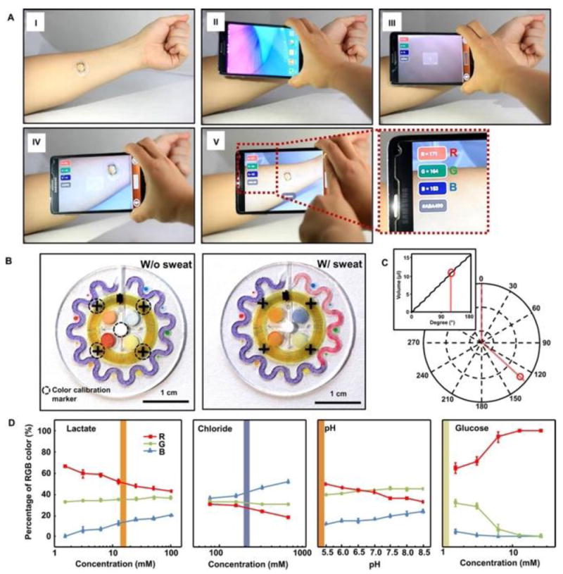
Soft colorimetric sensing patch159 NFC interface to a smartphone and image processing approaches. (A) Pictures demonstrating NFC between a sweat monitoring device and a smartphone to launch software for image capture and analysis. (B) Images of the epidermal microfluidic biosensor (left) before and (right) after injecting artificial sweat. (C) Location tracking of sweat accumulation with polar coordinates and their relationship to total captured volume of sweat (inset). (D) Standard calibration curves between normalized %RGB value and concentration of markers for quantitative analysis (n = 3, error bars represent the SD). Each vertical colored bar represents the marker concentration determined from the corresponding reservoirs in the right image of (B) as an example.
Arguably, in the future, many wearable chemical sensors will be chemical-to-electrical or electrochemical in nature, because: (1) these types of sensors require no action on the user’s behalf to observe or record the data; (2) in some cases these sensors can minimize the required technology (no light sources, optics, or detectors, are required); (3) many of these sensors are reagent and label-free such that they start working as soon as they are brought into contact with biofluid; (4) importantly, many electrochemical sensors are continuous (reversible). Therefore, the bulk of our discussion in this section will focus on wearable electrochemical sensors. 160-162
Electrochemical sensors represent an important subclass of chemical sensors in which an electrode serves as the transducer. Such sensors rely on the interplay between electricity and chemistry, namely the measurements of electrical quantities, such as potential of current, and their relationship to the concentration of the target analyte. Unlike other types of chemical measurements involving the bulk solution, electrochemical reactions occur at the electrode/solution interface. According to the electrical parameter that they measure, the two major classes of widely-demonstrated electrochemical sensors are potentiometric and amperometric devices (Figure 16a, b). Both types of electrochemical sensors require at least two electrodes (working and reference) and a contacting sample solution, that constitute the electrochemical cell. High performance sensors often add a third reference electrode which helps stabilize the sensor system over time (avoid sensor drift) and therefore help limit the changes in the transduced signal to be only that of the specific analyte that is to be measured.163
Figure 16.
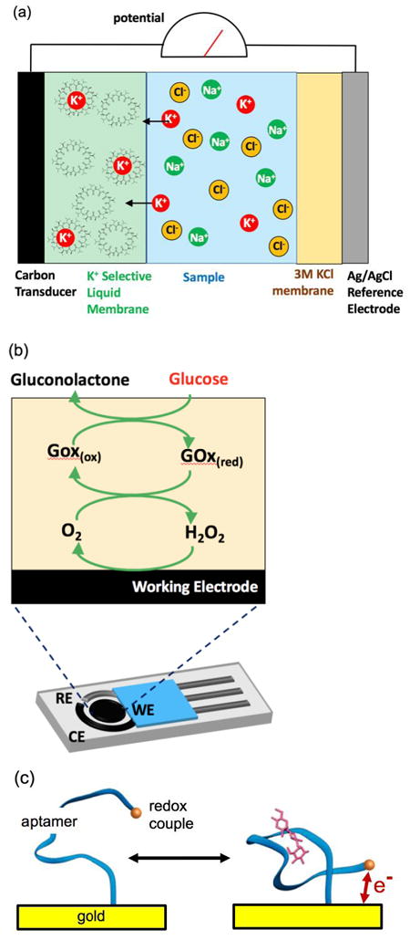
Examples of continuous electrochemical sensing modalities including (a) ion-selective/potentiometric, (b) enzymatic/amperometric where RE is reference electrode, CE is counter electrode, and WE is the working electrode, and (c) simple representation of aptamer-based sensing. Only (a) and (b) have been demonstrated in non-invasive wearable sensors while (c) has only been demonstrated in invasive sensing formats (in circulating blood165). Generally the detection ranges are mM’s for (a), down to μM’s for (b) and down to nM’s for (c).
Potentiometric sensors such as ion-selective electrodes (ISE), rely on measuring a potential response associated with the selective recognition of the target ionic analyte (Figure 16a). The signal is measured as the potential difference (voltage) between the working electrode and the reference electrode (for simplicity, only a two-electrode system is shown in Fig. 16a). A critical material in the potentiometric sensor is an electrode coated with a membrane that selectively allows passage of only one ionic species that will dominate the voltage signal. For example, a PVC membrane coating that is embedded with sodium ionophore-X will selectively pass only Na+ ions where as a membrane embedded with valinomycin will selectively pass K+ ions (interestingly valinomycin is also a potent antibiotic as it induces K+ conductivity in cell membranes). Now, the higher the concentration of ions in solution, the greater the number of ions that will diffuse into the membrane and to the electrode. Because only the cation passes intothe membrane (Na+ or K+), this results in a buildup of electrical potential (voltage) across the membrane. The voltage is theoretically dependent on the logarithm of the ionic activity (e.g. the Nernst equation164).
Amperometric sensors involve electron transfer processes across the electrode/solution interface and rely on measuring the current signal when a potential is applied between working and reference electrodes. The applied potential is used for driving the electron-transfer reaction of the target analyte while the resulting current signal is proportional to the analyte concentration. Most amperometric sensors rely on an immobilized enzyme to make them specific to a particular analyte. For example, with a glucose electrode, glucose reacts with immobilized glucose oxidase enzyme, and the current response associated with this reaction (or reaction products) can be measured as an electrical current (Figure 16b).160,161
Unfortunately, ion-selective and amperometric electrodes are generally limited to milli-molar concentrations of ions (electrolytes) and micro-molar or greater ranges of metabolites, respectively. This is far short of the wide-array analytes that exist in secreted biofluids. Few other options exist, and the most attractive options will also be single step (just place them in biofluid) and inherently reversible just like ion-selective and enzymatic electrodes. One of the more promising options may be electrochemical aptamer-based (EAB) sensors, which can work continuously even in whole blood (Figure 16c).165 EAB sensors require an aptamer (DNA sequence) that selectively bind and releases an analyte at actual concentrations for the analyte in the biofluid. The binding event must also cause a shape change, which therefore changes the positon of an attached redox couple relative to the electrode surface, and therefore electrochemical activity. Simply, as the redox couple is brought closer or further away from the electrode, the measured electrochemical current at the redox potential increases or decreases respectively.
Chemical Sensors: Devices and Demonstrations
Electrochemical devices meet the requirements of on-body wearable systems owing to their inherent miniaturization, low-power requirements, simplicity, speed and low-cost fabrication. Over the past 5 years we have witnessed significant progress in the field of wearable electrochemical sensors.160,161,166 Wearable electrochemical sensors have been integrated directly on the epidermis or onto textile materials for variety of chemical monitoring applications. Sweat, saliva and tears have been used for such non-invasive real-time electrochemical monitoring since these biofluids contain multiple physiologically relevant chemical constituents. Several groups have thus developed wearable electrochemical sensors for real-time non-invasive monitoring of various metabolites and electrolytes, including most recently numerous devices demonstrated for sweat (Figure 17)
Figure 17.
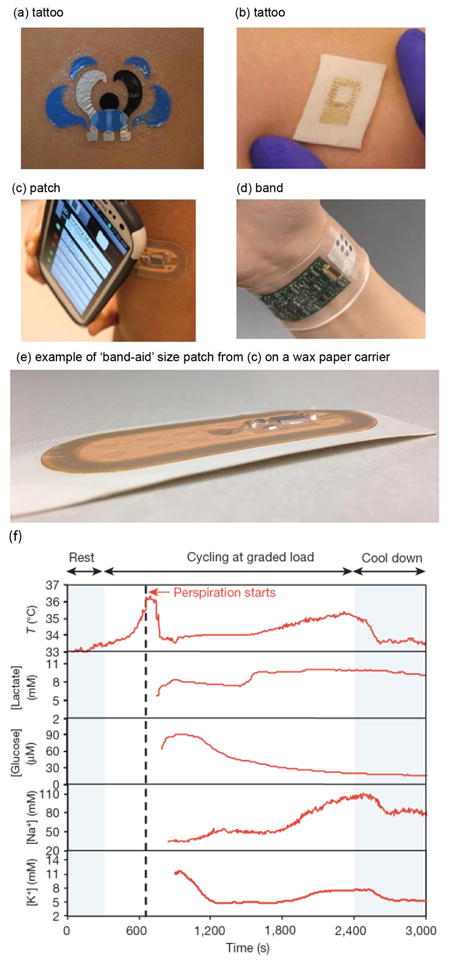
Bringing electrochemcial sensors directly onto skin to detect sweat (adapted).158 In all the examples provided in the figure, technology is mechanically compliant to skin, which is a first step to reduce the sweat volume between skin and sensors. The data shown in (f) is for a human-subject wearing the technology shown in (d).178
In existing demonstrations, epidermal electrochemical sensors mate intimately with the skin, and hence must be soft and sometimes also stretchable to ensure such conformal contact. Recent efforts have illustrated the use of specially engineered stress-enduring inks for screen-printing of stretchable electrochemical sensors that withstand severe mechanical strain with minimal effect on their performance.167. Flexible tattoo and textile-based amperometric or potentiometric sensors have thus been demonstrated for the detection of different chemical markers in human sweat (Figure 17a). For example, Jia et al described real-time non-invasive lactate biosensing in sweat during exercise activity using a flexible printed temporary-transfer tattoo enzyme electrode that conformed to the wearer’s skin.168 The epidermal lactate biosensor was fabricated with a mediated lactate oxidase recognition layer, covered by a biocompatible chitosan layer. Temporal current-time lactate profiles illustrated the suitability of this epidermal biosensor to assess the degree of physical exertion primarily because as exertion increases, sweat rate increases, and lactate concentrations depend on sweat rate.59 Subsequent work from Wang’s group has led to epidermal glucose tattoo biosensors that combine an iontophoretic extraction with electrochemical detection using the corresponding amperometric enzyme electrodes.169,170 The ability to detect the rise in the glucose or alcohol level after a meal or a drink in a non-invasive fashion was demonstrated. The transdermal alcohol sensor integrates a sweat-secretion stimulating drug (pilocarpine)-loaded iontophoretic operation and amperometric biosensing to offer rapid alcohol measurements in the induced sweat (Figure 18). More recently, sweat stimulation integration has been demonstrated where the sweat stimulation and sensing components are properly spatially separated, which is important to improve the quality of collected data.171
Figure 18.

Tattoo-based transdermal alcohol sensor. (A) Schematic diagram of an iontophoretic-sensing tattoo device, containing the iontophoretic electrodes (IEs; anode and cathode) and the three sensing electrodes (working, reference, and counter electrodes: WE, RE, and CE, respectively). (B) Photograph of an alcohol iontophoretic-sensing tattoo device with integrated flexible electronics applied to a human subject. (C) Schematic diagram of a wireless operation of the iontophoretic-sensing tattoo device for transdermal alcohol sensing. In the diagrams of the tattoo-base device, blue and red highlights show the active zones during iontophoresis and amperometric detection, respectively. (D) Schematic diagram of constituents in the iontophoretic system (left) and of the reagent layer and processes involved in the amperometric sensing of ethanol on the working electrode (right).
The monitoring of sweat electrolytes concentrations can shed useful information on the chemical and physical state of the body.59,158 Diamond’s group described an ISE based Sweat Sensor Belt (SSB) that combines sweat collection and analysis conveniently in a single device.172 The same group introduced potentiometric sensors for sweat sodium.173 Classical potentiometric sensors are commonly constructed using rigid materials that do not comply with the elastic nature of the human skin, making such potentiometric sensors uncomfortable to the wearer. Solid-contact flexible ISE’s have thus been developed as wearable potentiometric sensors for calcium, ammonium and sodium ions.163,174,175 These skin-worn potentiometric sensors offer resiliency against mechanical deformations experienced on the skin and display a near-Nernstian response with negligible carryover. Rogers’s team described recently a multiplexed array of potentiometric sensors for spatio-temporal mapping of a localized ion concentration.161 Such body-compliant potentiometric sensor array monitors continuously transient electrolyte concentration profiles to alert the wearer of potential health risks. Skin-worn electrochemical sensors for trace metals (e.g., Zn, Pb) have been described in connection to highly sensitive stripping voltammetry detection.176,177 Such detection involves an electrodeposition (preconcentration) step to offer detection limits down to the ppb (nanomomolar) concentration level.
Integrated real-time multi-analyte monitoring is essential to a widespread future adoption of wearable electrochemical sensors. Gao et al developed an integrated multi-analyte potentiometric-amperometric sensor wristband platform (Figure 17d,f).178 Such sweat-bands can track the wearer’s temperature, glucose, lactate, potassium and sodium from exercise induced sweat, although lactate and sodium are primarily indicative of sweat generation rate.59,158 This new multi-sensor epidermal platform merged the plastic-based sensor array with silicon integrated circuits consolidated on a flexible circuit board for advanced signal conditioning, processing and transmission. Selective independent operation of individual sensors has been demonstrated along with sweat profile of human subjects engaged in prolonged indoor and outdoor physical activities.
Saliva or tears offers attractive alternatives for wearable electrochemical sensing applications. The non-invasive monitoring of glucose in tears has received particular attention in connection to the management of diabetes (Figure 19).179,180 For example, Yao et al described a microfabricated amperometric glucose sensor integrated onto a contact lens.180 The glucose oxidase enzyme was immobilized in a titania sol–gel layer that led to enhanced sensitivity, along with a permselective (anti-interference) Nafion® coating. These developments could pave the way to multi-functional contact lens capable of non-invasive chemical analysis.181 Saliva contains multiple biomarkers that can shed useful insights into the health status. Potentiometric pH and fluoride ion-selective electrodes on a partial denture have been described already in the 1960s.182,183 Kim et al has developed an integrated wireless mouthguard platform for amperometric monitoring of salivary metabolites.184,185 A Bluetooth Low Energy (BLE) chipset provided wireless connectivity to different BLE-enabled devices. The utility of the integrated mouthguard amperometric biosensor was demonstrated for real-time monitoring of salivary uric acid for both healthy people and hyperuricemia patients. Such a mouthguard sensor platform can be readily expanded to multiple salivary analytes.
Figure 19.

The contact lens sensor that was under co-development by Google and Novartis (effort ceased) measures glucose concentration in tears using a miniaturized electrochemical glucose sensor and a wireless chip and antenna ring. Copyright 2014, Google X.
Chemical Sensors: Unmet Challenges and Outlook
Despite of significant recent progress toward wearable chemical sensors, wearable chemical sensors have technological gaps to fill before realizing their full potential. Challenges related to the analytical procedure, power, materials, communication, data acquisition and security, and seamless integration have been discussed recently.162 A major challenge, as discussed at the end of the subsection Chemical Sensors: Body-to-Signal Transduction is the development and in-vivo validation of electrochemical sensors beyond the ion-selective and enzymatic modalities that have been around for decades. Furthermore, effective sampling and transport of biofluids (e.g. sweat) over the sensor surface is crucial for ensuring good reproducibility and avoiding contamination. Therefore, simply placing a sensor against the body surface may be inadequate. Furthermore, non-invasive biofluids are not as reliable as blood, and analyte concentrations are often diluted and in some cases, will require preconcentraiton techniques.158 A major opportunity could be hormone sensing, because many hormones are small and lipophilic, and therefore have a 1:1 ratio in their unbound fractions between blood and secreted biofluids.158 Industry remains skeptical of the potential impact of these fluids, but at the same time, breakthroughs solving fundamental and confounding challenges continue.15,171 Some on-skin chemical sensing products do exist, such as sweat Cl- testing for infant Cystic Fibrosis testing158, but these are point-of-care type devices in a medical setting, and not a true wearable device. Therefore, no commercial wearable sensing products yet exist for chemical detection with sweat, tears, or saliva, but startup companies such as Eccrine Systems (sweat) and MouthSense (saliva) are gathering increased attention and investment.186
The challenge of development and in-vivo validation of electrochemical sensors beyond ion-selective and enzymatic modalities is worthy of further discussion. There is a very large spectrum of chemical sensors reported in the literature. For wearable sensors, there are some very important considerations that are unresolved, especially in the many publications of sensors stated as potentially useful for wearable applications. In wearable applications, the analyte to be detected will likely be in whole biofluid, so sensor selectivity is critical. In a wearable application, the greatest value is for continuous sensing, so the sensor should be inherently reversible, and the signal changes due to fouling and non-specific binding must be very low or corrected for by some other means. Ion-selective electrodes, and EAB sensors, are less sensitive to surface fouling because the charge-transduction mechanisms are fully localized to the sensor surface. This is not true for most other types of charge, impedance, and field-effect chemical sensors found in literature. Therefore, fundamental research on new and more robust electrochemical sensors is a critically important research area for wearable applications.
Chemical Sensors: Prospects for Lab on a Chip Integration
As noted in the introduction, is fitting that this review is published here in the journal Lab on a Chip, because addressing challenges in wearable sensors, will require innovative miniaturization of analytical techniques currently only found in bench-top and point-of-care settings. It is further fitting of this journal, because creating continuous sensors is one of the next major frontiers for the field, building on the many breakthroughs previously reported in this journal for one-time point-of-care sensors. In the last section of this review, we will touch upon what roles traditional lab on a chip technology may play in wearables. Certainly, not every condition or analyte can be measured through a simple press-against-skin sensor. Rather, in some cases fluid handling, preconcentration, incubation, and other techniques may be required to satisfy the most challenging applications in detection.
Some of the most valuable contributions by introducing a microfluidic or lab-on-a-chip approach are the abilities to mix, introduce, concentrate, and perform other useful functions on solutes. This is particularly powerful, because for almost every blood analyte of great interest, there is an existing assay performed in fluid environments such as conventional 96-well plate assays. Microfluidics offers the potential to leverage these existing systems. Lateral flow assays (LFAs) are a great example of a miniaturized and ultra-simple assay system, and have been widely used to measure a variety of biological samples including urine, saliva, sweat, etc., but such devices are single-use, often not highly quantitative, and therefore their applicability in wearable applications may be very limited.
In this review, we have stated that wearables often require continuous sensing. But continuous does not mean ‘all the time’, rather it means giving the user, a doctor, an athletic trainer, etc. enough data points that biologically relevant information is provided, and/or such that baseline conditions can be recorded before a physiological event occurs. The required data points could be every few minutes (e.g. monitoring stress responses through cortisol concentrations), every 10’s of minutes (such as measuring blood sugar levels), or every few hours (e.g. monitoring injury or illness through changes in inflammatory protein biomarkers). If the sampling interval is hours, for example, that could allow ample time to concentrate, mix, incubate, and perform other functions normally only found on the benchtop. However, a wearable normally must be tiny in size, and ideally controlled by a simple electronic chip. Therefore, conventional pressure-based transport, valving, and other functions in microfluidics may be less preferable to methods such as electrowetting control of digital microfluidics.187 The big question for each application will often be, ‘which is more painful, to develop the simple and robust electrochemical sensor, or to develop a sophisticated and complex microfluidic lab-on-chip platform?’. The latter, again, suggests opportunities for researchers in lab-on-chip, if they can figure out how move beyond the frontier of point-of-care and bench-top devices to fully portable, tiny, and continuous sensing modalities.
Conclusions and General Outlook
Market segment projections for wearable sensors in 2020 are shown in Figure 20. As this data was from 2016, it does not include the recently slower-than-expected pace of introduction of non-invasive wearable chemical sensors. Likely, in 2020 and shortly beyond, biopotential (electrical) and optical sensors will still dominate the wearable sensors market. As stated earlier in this review, inertial sensors are not within the scope of this review as they do not measure information coming from within the body.
Figure 20.

Pie chart of market size forecasts for 2020 by sensor type, courtesy James Haward of IDTechEx. The pie chart includes all wearable sensors that measure from the body and therefore excludes environmental sensors. Although not covered in this review, the chemical sensors are mainly continuous glucose monitors which are invasive as they place a sensor into the dermis using a small needle.
Other than side-by-side integration of electrical and optical sensing such as galvanic skin response and heart rate, the general sensing modalities of mechanical, electrical, optical, and chemical, have remained isolated from each other in commercial products. This will change over time, especially as more information, and more accurate information is demanded from wearable sensors. Simply, by combining a multitude of sensing modalities more selective and specific measures of physiological conditions can be determined. Furthermore, a more comprehensive picture of health can be provided. For example, instead of just measuring heart rate, could we understand the origin or cause of increased heart rate and attribute it as healthy or not (e.g. exercise vs. a cardiac event, or positive excitement vs. a panic attack, etc.). Recently, Wang and Mercier described a multi-modal epidermal Chem-Phys tattoo platform coupling sweat lactate and heart-rate monitoring.188 Such hybrid wearable sensors, fusing chemical, physical and electrophysiological sensors on the same platform, should offer a more comprehensive monitoring and understanding of an individual’s physiological state. This theme of providing increased information and increased relevancy of the information will perhaps guide most of the future technological breakthroughs in wearable technology. At the same time, the use of more traditional mechanical, optical, and electrical sensors will continue to increase, mainly in specialized adaptation to applications not currently served but which could benefit from such measurement capabilities.
Many of the emerging sensing modalities, such as stretchable mechanical sensors or chemical sensors, require disposable components including adhesives and the sensors themselves. Adhesives can only last as long as it takes for the stratum corneum to fully refresh itself (weeks), and practically have difficulty lasting longer than several days in many instances (skin oils, bathing, irritation, etc.). Most chemical sensors are susceptible to fouling, or utilize probe chemistries that are consumed or which slowly degrade over time. Therefore, unlike todays academic demonstrations, commercial devices will need strategies for easily attaching and detaching disposable components (sensors, adhesives, etc.) with reusable components (batteries, electronics, plastic housings, etc.).
For all of these future endeavors continued investment in research and development is paramount. It is our hope that this review has served as a baseline for those interested in contributing to this future, and as way to direct talent to solving the many fundamental challenges and obstacles that currently exist for wearable sensors.
Acknowledgments
The authors at the Univ. of Cincinnati acknowledge support from the National Science Foundation and the industrial members of the Center for Advanced Design and Manufacturing of Integrated Microfluidics (NSF I/UCRC award number IIP-1362048), the Air Force Research Labs Award #USAF contract # FA8650-15-C-6625, and from NSF EPDT Award #1608275. Joseph Wang is supported by the Defense Threat Reduction Agency Joint Science and Technology Office for Chemical and Biological Defense (HDTRA 1-16-1-0013) and the UCSD Center for Wearable Sensors (CWS). John Rogers acknowledges support from the Center for Bio-Integrated Electronics at the Simpson/Querrey Institute, Northwestern University. Funding support for Tingrui Pan and Michelle Khine has not been disclosed.
Footnotes
Competing Financial Interests
The co-author (Heikenfeld) discloses a potential conflict of interest as he is a co-founder of Eccrine Systems Inc. which is commercializing sweat bio-sensing technologies. John Rogers is involved with several companies that are developing wearable technologies. Joseph Wang has no competing financial interests to disclosed. No potential conflict of interests exist for Tingrui Pan or Michelle Khine.
References
- 1.Clarke SF, Foster JR. Br J Biomed Sci. 2012;69:83–93. [PubMed] [Google Scholar]
- 2.Miller J. Inventing the Apollo Spaceflight Biomedical Sensors. https://airandspace.si.edu/stories/editorial/inventing-apollo-spaceflight-biomedical-sensors.
- 3.Cunningham DD. In Vivo Glucose Sensing. John Wiley & Sons, Inc.; Hoboken, NJ, USA: 2010. pp. 191–215. [Google Scholar]
- 4.Proksch E, Brandner JM, Jensen J-M. Exp Dermatol. 2008;17:1063–1072. doi: 10.1111/j.1600-0625.2008.00786.x. [DOI] [PubMed] [Google Scholar]
- 5.Deli MA. Biochim Biophys Acta - Biomembr. 2009;1788:892–910. doi: 10.1016/j.bbamem.2008.09.016. [DOI] [PubMed] [Google Scholar]
- 6.El-Laboudi A, Oliver NS, Cass A, Johnston D. Diabetes Technol Ther. 2013;15:101–15. doi: 10.1089/dia.2012.0188. [DOI] [PubMed] [Google Scholar]
- 7.Pinkus H. G Ital Dermatol Minerva Dermatol. 1966;107:1115–26. [PubMed] [Google Scholar]
- 8.Mitragotri S. Adv Drug Deliv Rev. 2013;65:100–103. doi: 10.1016/j.addr.2012.07.016. [DOI] [PubMed] [Google Scholar]
- 9.Yarmush ML, Golberg A, Serša G, Kotnik T, Miklavčič D. Annu Rev Biomed Eng. 2014;16:295–320. doi: 10.1146/annurev-bioeng-071813-104622. [DOI] [PubMed] [Google Scholar]
- 10.Leboulanger B, Guy RH, Delgado-Charro MB. Physiol Meas. 2004;25:R35–R50. doi: 10.1088/0967-3334/25/3/r01. [DOI] [PubMed] [Google Scholar]
- 11.Levin J, Maibach H. J Control Release. 2005;103:291–299. doi: 10.1016/j.jconrel.2004.11.035. [DOI] [PubMed] [Google Scholar]
- 12.Grice EA, Segre JA. Nat Rev Microbiol. 2011;9:244–253. doi: 10.1038/nrmicro2537. [DOI] [PMC free article] [PubMed] [Google Scholar]
- 13.Boysen TC, Yanagawa S, Sato F, Sato K. J Appl Physiol. 1984;56:1302–7. doi: 10.1152/jappl.1984.56.5.1302. [DOI] [PubMed] [Google Scholar]
- 14.Picardo M, Ottaviani M, Camera E, Mastrofrancesco A. Dermatoendocrinol. 2009;1:68–71. doi: 10.4161/derm.1.2.8472. [DOI] [PMC free article] [PubMed] [Google Scholar]
- 15.Peng R, Sonner Z, Hauke A, Wilder E, Kasting J, Gaillard T, Swaille D, Sherman F, Mao X, Hagen J, Murdock R, Heikenfeld J. Lab Chip. 2016;16:4415–4423. doi: 10.1039/c6lc01013j. [DOI] [PubMed] [Google Scholar]
- 16.Silver FH, Freeman JW, DeVore D. Skin Res Technol. 2001;7:18–23. doi: 10.1034/j.1600-0846.2001.007001018.x. [DOI] [PubMed] [Google Scholar]
- 17.Ní Annaidh A, Bruyère K, Destrade M, Gilchrist MD, Otténio M. J Mech Behav Biomed Mater. 2012;5:139–148. doi: 10.1016/j.jmbbm.2011.08.016. [DOI] [PubMed] [Google Scholar]
- 18.Pailler-Mattei C, Bec S, Zahouani H. Med Eng Phys. 2008;30:599–606. doi: 10.1016/j.medengphy.2007.06.011. [DOI] [PubMed] [Google Scholar]
- 19.Liang Xing, Boppart SA. IEEE Trans Biomed Eng. 2010;57:953–959. doi: 10.1109/TBME.2009.2033464. [DOI] [PMC free article] [PubMed] [Google Scholar]
- 20.Kuwazuru O, Saothong J, Yoshikawa N. Med Eng Phys. 2008;30:516–522. doi: 10.1016/j.medengphy.2007.06.001. [DOI] [PubMed] [Google Scholar]
- 21.Moore TJ, Mundie JR. J Acoust Soc Am. 1972;52:577–584. [Google Scholar]
- 22.Edwards C, Marks R. Clin Dermatol. 1995;13:375–380. doi: 10.1016/0738-081x(95)00078-t. [DOI] [PubMed] [Google Scholar]
- 23.Potts RO, Chrisman DA, Buras EM. J Biomech. 1983;16:365–72. doi: 10.1016/0021-9290(83)90070-2. [DOI] [PubMed] [Google Scholar]
- 24.Johnston ID, McCluskey DK, Tan CKL, Tracey MC. J Micromechanics Microengineering. 2014;24:35017. [Google Scholar]
- 25.Amjadi M, Yoon YJ, Park I. Nanotechnology. 2015;26:375501. doi: 10.1088/0957-4484/26/37/375501. [DOI] [PubMed] [Google Scholar]
- 26.Kim J, Park S-J, Nguyen T, Chu M, Pegan JD, Khine M. Appl Phys Lett. 2016;108:61901. doi: 10.1063/1.4941439. [DOI] [PMC free article] [PubMed] [Google Scholar]
- 27.Park S-J, Kim J, Chu M, Khine M. Adv Mater Technol. 2016;1:1600053. [Google Scholar]
- 28.Atalay O, Kennon WR, Demirok E. IEEE Sens J. 2015;15:110–122. [Google Scholar]
- 29.Yamada T, Hayamizu Y, Yamamoto Y, Yomogida Y, Izadi-Najafabadi A, Futaba DN, Hata K. Nat Nanotechnol. 2011;6:296–301. doi: 10.1038/nnano.2011.36. [DOI] [PubMed] [Google Scholar]
- 30.Wehrle G, Nohama P, Kalinowski HJ, Torres PI, Valente LCG. Meas Sci Technol. 2001;12:805–809. [Google Scholar]
- 31.Wang Y, Wang L, Yang T, Li X, Zang X, Zhu M, Wang K, Wu D, Zhu H. Adv Funct Mater. 2014;24:4666–4670. [Google Scholar]
- 32.Pang Y, Tian H, Tao L, Li Y, Wang X, Deng N, Yang Y, Ren T-L. ACS Appl Mater Interfaces. 2016;8:26458–26462. doi: 10.1021/acsami.6b08172. [DOI] [PubMed] [Google Scholar]
- 33.Castro ID, Morariu R, Torfs T, Van Hoof C, Puers R. 2016 IEEE Int Symp Med Meas Appl. 2016:1–6. [Google Scholar]
- 34.Suhling JC, Jaeger RC. IEEE Sens J. 2001;1:14–30. [Google Scholar]
- 35.Wang Y, Wang AX, Wang Y, Chyu MK, Wang Q-M. Sensors Actuators A Phys. 2013;199:265–271. [Google Scholar]
- 36.Yao S, Zhu Y. Nanoscale. 2014;6:2345. doi: 10.1039/c3nr05496a. [DOI] [PubMed] [Google Scholar]
- 37.Chen Zhenhai, Luo RC. IEEE Trans Ind Electron. 1998;45:886–894. [Google Scholar]
- 38.Zhao X, Hua Q, Yu R, Zhang Y, Pan C. Adv Electron Mater. 2015;1:1500142. [Google Scholar]
- 39.Pashley DW. Proc R Soc A Math Phys Eng Sci. 1960;255:218–231. [Google Scholar]
- 40.Spaepen F. Acta Mater. 2000;48:31–42. [Google Scholar]
- 41.Lacour SP, Jones J, Wagner S, Li T, Suo Z. Proc IEEE. 2005;93:1459–1466. [Google Scholar]
- 42.Park S, Ahn J, Feng X, Wang S, Huang Y, Rogers JA. Adv Funct Mater. 2008;18:2673–2684. [Google Scholar]
- 43.Gleskova H, Wagner S, Suo Z. J Non Cryst Solids. 2000;266–269:1320–1324. [Google Scholar]
- 44.Li T, Huang ZY, Xi ZC, Lacour SP, Wagner S, Suo Z. Mech Mater. 2005;37:261–273. [Google Scholar]
- 45.Byun I, Coleman AW, Kim B. J Micromechanics Microengineering. 2013;23:85016. [Google Scholar]
- 46.Lu N, Lu C, Yang S, Rogers J. Adv Funct Mater. 2012;22:4044–4050. [Google Scholar]
- 47.Lu N, Wang X, Suo Z, Vlassak J. Appl Phys Lett. 2007;91:2–4. [Google Scholar]
- 48.Li T, Huang Z, Suo Z, Lacour SP, Wagner S. Appl Phys Lett. 2004;85:3435–3437. [Google Scholar]
- 49.Li T, Suo Z. Int J Solids Struct. 2007;44:1696–1705. [Google Scholar]
- 50.Yao S, Zhu Y. JOM. 2016;68:1145–1155. [Google Scholar]
- 51.Chi YM, Jung TP, Cauwenberghs G. IEEE Rev Biomed Eng. 2010;3:106–119. doi: 10.1109/RBME.2010.2084078. [DOI] [PubMed] [Google Scholar]
- 52.Marks JG, Miller JJ. Lookingbill and Marks’ Principles of Dermatology. 2013 [Google Scholar]
- 53.McAdams ET, Jossinet J, Lackermeier A, Risacher F. Med Biol Eng Comput. 1996;34:397–408. doi: 10.1007/BF02523842. [DOI] [PubMed] [Google Scholar]
- 54.Harding CR. Dermatol Ther. 2004;17:6–15. doi: 10.1111/j.1396-0296.2004.04s1001.x. [DOI] [PubMed] [Google Scholar]
- 55.Chizmadzhev YA, Indenbom AV, Kuzmin PI, Galichenko SV, Weaver JC, Potts RO. Biophys J. 1998;74:843–856. doi: 10.1016/S0006-3495(98)74008-1. [DOI] [PMC free article] [PubMed] [Google Scholar]
- 56.Oh SY, Leung L, Bommannan D, Guy RH, Potts RO. J Control Release. 1993;27:115–125. [Google Scholar]
- 57.Christian T, Gorm Krogh J, Sverre G, Ørjan GM. Physiol Meas. 2010;31:1395. [Google Scholar]
- 58.Lopez-Gordo M, Sanchez-Morillo D, Valle F. Sensors. 2014;14:12847. doi: 10.3390/s140712847. [DOI] [PMC free article] [PubMed] [Google Scholar]
- 59.Sonner Z, Wilder E, Heikenfeld J, Kasting G, Beyette F, Swaile D, Sherman F, Joyce J, Hagen J, Kelley-Loughnane N, Naik R. Biomicrofluidics. 2015;9:31301. doi: 10.1063/1.4921039. [DOI] [PMC free article] [PubMed] [Google Scholar]
- 60.Ha S, Kim C, Chi YM, Akinin A, Maier C, Ueno A, Cauwenberghs G. IEEE Trans Biomed Eng. 2014;61:1522–1537. doi: 10.1109/TBME.2014.2308552. [DOI] [PubMed] [Google Scholar]
- 61.Yeo W, Kim Y, Lee J, Ameen A, Shi L, Li M, Wang S, Ma R, Jin SH, Kang Z. Adv Mater. 2013;25:2773–2778. doi: 10.1002/adma.201204426. [DOI] [PubMed] [Google Scholar]
- 62.Gandhi N, Khe C, Chung D, Chi YM, Cauwenberghs G. 2011 International Conference on Body Sensor Networks; IEEE; 2011. pp. 107–112. [Google Scholar]
- 63.Mathewson KE, Harrison TJL, Kizuk SAD. Psychophysiology. 2017;54:74–82. doi: 10.1111/psyp.12536. [DOI] [PubMed] [Google Scholar]
- 64.Bashkatov AN, Genina EA, Kochubey VI, Tuchin VV. J Phys D Appl Phys. 2005;38:2543. [Google Scholar]
- 65.Anderson RR, Parrish JA. J Invest Dermatol. 1981;77:13–19. doi: 10.1111/1523-1747.ep12479191. [DOI] [PubMed] [Google Scholar]
- 66.Odland GF. Physiol Biochem Mol Biol Ski. 1991;1:3–62. [Google Scholar]
- 67.Chedekel MR. In: Melanin: Its Role in Human Photoprotection. C MR, Zeise TBFL, editors. Blackwell Science Inc; 1994. pp. 11–12. [Google Scholar]
- 68.Scheuplein RJ. J Soc Cosmet Chem. 1964;15:111–122. [Google Scholar]
- 69.Tuchin VV, Tuchin V. Tissue Optics, Light Scattering Methods and Instruments for Medical Diagnostics. Vol. 13 SPIE Press; 2007. [Google Scholar]
- 70.Ferrari M, Quaresima V. Neuroimage. 2012;63:921–935. doi: 10.1016/j.neuroimage.2012.03.049. [DOI] [PubMed] [Google Scholar]
- 71.Boucouvalas AC. IEE Proc - Optoelectron. 1996;143:334–338. [Google Scholar]
- 72.Izzetoglu M, Devaraj A, Bunce S, Onaral B. IEEE Trans Biomed Eng. 2005;52:934–938. doi: 10.1109/TBME.2005.845243. [DOI] [PubMed] [Google Scholar]
- 73.Hayes MJ, Smith PR. In: BiOS Europe’98. Baldini F, Croitoru NI, Frenz M, Lundstroem I, Miyagi M, Pratesi R, Wolfbeis OS, editors. Vol. 3570. International Society for Optics and Photonics; 1999. p. 138. [Google Scholar]
- 74.Luo N, Dai W, Li C, Zhou Z, Lu L, Poon CCY, Chen SC, Zhang Y, Zhao N. Adv Funct Mater. 2016;26:1178–1187. [Google Scholar]
- 75.Zhu SE, Krishna Ghatkesar M, Zhang C, Janssen GCAM. Appl Phys Lett. 2013;102:2014–2017. [Google Scholar]
- 76.Obitayo W, Liu T, Obitayo W, Liu T. J Sensors. 2012;2012:1–15. [Google Scholar]
- 77.Kang D, Pikhitsa PV, Choi YW, Lee C, Shin SS, Piao L, Park B, Suh K-Y, Kim T, Choi M. Nature. 2014;516:222–226. doi: 10.1038/nature14002. [DOI] [PubMed] [Google Scholar]
- 78.Li M, Li H, Zhong W, Zhao Q, Wang D. ACS Appl Mater Interfaces. 2014;6:1313–1319. doi: 10.1021/am4053305. [DOI] [PubMed] [Google Scholar]
- 79.Lipomi DJ, Vosgueritchian M, Tee BC-K, Hellstrom SL, Lee Ja, Fox CH, Bao Z. Nat Nanotechnol. 2011;6:788–792. doi: 10.1038/nnano.2011.184. [DOI] [PubMed] [Google Scholar]
- 80.Amjadi M, Pichitpajongkit A, Lee S, Ryu S, Park I. ACS Nano. 2014;8:5154–5163. doi: 10.1021/nn501204t. [DOI] [PubMed] [Google Scholar]
- 81.Pegan JD, Zhang J, Chu M, Nguyen T, Park S-J, Paul A, Kim J, Bachman M, Khine M, Falgout L, Bajema M, Coleman T, Gregoire D, Larsen RJ, Huang Y, Rogers JA. Nanoscale. 2016;8:17295–17303. doi: 10.1039/c6nr04467k. [DOI] [PMC free article] [PubMed] [Google Scholar]
- 82.Bin Yao H, Ge J, Wang CF, Wang X, Hu W, Zheng ZJ, Ni Y, Yu SH. Adv Mater. 2013;25:6692–6698. doi: 10.1002/adma.201303041. [DOI] [PubMed] [Google Scholar]
- 83.Wei Y, Chen S, Dong X, Lin Y, Liu L. Carbon N Y. 2017;113:395–403. [Google Scholar]
- 84.Pan L, Chortos A, Yu G, Wang Y, Isaacson S, Allen R, Shi Y, Dauskardt R, Bao Z. Nat Commun. 2014;5:3002. doi: 10.1038/ncomms4002. [DOI] [PubMed] [Google Scholar]
- 85.Tolvanen J, Hannu J, Jantunen H. IEEE Sens J. 2017;17:4735–4746. [Google Scholar]
- 86.Wong RDP, Posner JD, Santos VJ. Sensors and Actuators a-Physical. 2012;179:62–69. [Google Scholar]
- 87.Li T, Luo H, Qin L, Wang X, Xiong Z, Ding H, Gu Y, Liu Z, Zhang T. Small. 2016;12:5042–5048. doi: 10.1002/smll.201600760. [DOI] [PubMed] [Google Scholar]
- 88.Wang J, Jiu J, Nogi M, Sugahara T, Nagao S, Koga H, He P, Suganuma K. Nanoscale. 2015;7:2926–2932. doi: 10.1039/c4nr06494a. [DOI] [PubMed] [Google Scholar]
- 89.Lee J, Kwon H, Seo J, Shin S, Koo JH, Pang C, Son S, Kim JH, Jang YH, Kim DE, Lee T. Adv Mater. 2015;27:2433–2439. doi: 10.1002/adma.201500009. [DOI] [PubMed] [Google Scholar]
- 90.Tee BCK, Chortos A, Dunn RR, Schwartz G, Eason E, Bao ZA. Adv Funct Mater. 2014;24:5427–5434. [Google Scholar]
- 91.Park S, Kim H, Vosgueritchian M, Cheon S, Kim H, Koo JH, Kim TR, Lee S, Schwartz G, Chang H, Bao Z. Adv Mater. 2014;26:7324–7332. doi: 10.1002/adma.201402574. [DOI] [PubMed] [Google Scholar]
- 92.Schwartz G, Tee BC, Mei J, Appleton AL, Kim DH, Wang H, Bao Z. Nat Commun. 2013;4:1859. doi: 10.1038/ncomms2832. [DOI] [PubMed] [Google Scholar]
- 93.Tien NT, Jeon S, Kim DI, Trung TQ, Jang M, Hwang BU, Byun KE, Bae J, Lee E, Tok JB, Bao Z, Lee NE, Park JJ. Adv Mater. 2014;26:796–804. doi: 10.1002/adma.201302869. [DOI] [PubMed] [Google Scholar]
- 94.Mannsfeld SC, Tee BC, Stoltenberg RM, Chen CV, Barman S, Muir BV, Sokolov AN, Reese C, Bao Z. Nat Mater. 2010;9:859–864. doi: 10.1038/nmat2834. [DOI] [PubMed] [Google Scholar]
- 95.Chortos A, Liu J, Bao Z. Nat Mater. 2016;15:937–950. doi: 10.1038/nmat4671. [DOI] [PubMed] [Google Scholar]
- 96.Kim SY, Park S, Park HW, Park DH, Jeong Y, Kim DH. Adv Mater. 2015;27:4178–4185. doi: 10.1002/adma.201501408. [DOI] [PubMed] [Google Scholar]
- 97.Sun JY, Keplinger C, Whitesides GM, Suo Z. Adv Mater. 2014;26:7608–7614. doi: 10.1002/adma.201403441. [DOI] [PubMed] [Google Scholar]
- 98.Sun J-Y, Zhao X, Illeperuma WRK, Chaudhuri O, Oh KH, Mooney DJ, Vlassak JJ, Suo Z. Nature. 2012;489:133–136. doi: 10.1038/nature11409. [DOI] [PMC free article] [PubMed] [Google Scholar]
- 99.US20170010. US Pat. 2013
- 100.US20090033. US Pat. 2009
- 101.Nie B, Li R, Brandt JD, Pan T. Lab Chip. 2014;14:4344–4353. doi: 10.1039/c4lc00746h. [DOI] [PubMed] [Google Scholar]
- 102.Nie B, Li R, Brandt JD, Pan T. Lab Chip. 2014;14:1107–1116. doi: 10.1039/c3lc50994j. [DOI] [PubMed] [Google Scholar]
- 103.Nie B, Xing S, Brandt JD, Pan T. Lab Chip. 2012;12:1110–1118. doi: 10.1039/c2lc21168h. [DOI] [PubMed] [Google Scholar]
- 104.Li RY, Nie BQ, Digiglio P, Pan TR. Adv Funct Mater. 2014;24:6195–6203. [Google Scholar]
- 105.Li R, Nie B, Zhai C, Cao J, Pan J, Chi YW, Pan T. Ann Biomed Eng. 2016;44:2282–2291. doi: 10.1007/s10439-015-1498-x. [DOI] [PubMed] [Google Scholar]
- 106.Nie B, Li R, Cao J, Brandt JD, Pan T. Adv Mater. 2015;27:6055–6062. doi: 10.1002/adma.201502556. [DOI] [PubMed] [Google Scholar]
- 107.Park KI, Son JH, Hwang GT, Jeong CK, Ryu J, Koo M, Choi I, Lee SH, Byun M, Wang ZL, Lee KJ. Adv Mater. 2014;26:2514–2520. doi: 10.1002/adma.201305659. [DOI] [PubMed] [Google Scholar]
- 108.Dagdeviren C, Su Y, Joe P, Yona R, Liu Y, Kim YS, Huang Y, Damadoran AR, Xia J, Martin LW, Huang Y, Rogers JA. Nat Commun. 2014;5:4496. doi: 10.1038/ncomms5496. [DOI] [PubMed] [Google Scholar]
- 109.Li C, Wu PM, Lee S, Gorton A, Schulz MJ, Ahn CH. J Microelectromechanical Syst. 2008;17:334–341. [Google Scholar]
- 110.Mandal D, Yoon S, Kim KJ. Macromol Rapid Commun. 2011;32:831–837. doi: 10.1002/marc.201100040. [DOI] [PubMed] [Google Scholar]
- 111.Dagdeviren C, Shi Y, Joe P, Ghaffari R, Balooch G, Usgaonkar K, Gur O, Tran PL, Crosby JR, Meyer M, Su Y, Chad Webb R, Tedesco AS, Slepian MJ, Huang Y, Rogers JA. Nat Mater. 2015;14:728–736. doi: 10.1038/nmat4289. [DOI] [PubMed] [Google Scholar]
- 112.Xu S, Qin Y, Xu C, Wei Y, Yang R, Wang ZL. Nat Nanotechnol. 2010;5:366–373. doi: 10.1038/nnano.2010.46. [DOI] [PubMed] [Google Scholar]
- 113.Persano L, Dagdeviren C, Su Y, Zhang Y, Girardo S, Pisignano D, Huang Y, Rogers JA. Nat Commun. 2013;4:1633. doi: 10.1038/ncomms2639. [DOI] [PubMed] [Google Scholar]
- 114.US20160157. US Pat. 2016
- 115.Wen Z, Yeh MH, Guo H, Wang J, Zi Y, Xu W, Deng J, Zhu L, Wang X, Hu C, Zhu L, Sun X, Wang ZL. Sci Adv. 2016;2:e1600097. doi: 10.1126/sciadv.1600097. [DOI] [PMC free article] [PubMed] [Google Scholar]
- 116.Kim D, Lu N, Ma R, Kim Y, Kim R, Wang S, Wu J, Won SM, Tao H, Islam A. Science. 2011;333:838–843. doi: 10.1126/science.1206157. [DOI] [PubMed] [Google Scholar]
- 117.Fan JA, Yeo W-H, Su Y, Hattori Y, Lee W, Jung S-Y, Zhang Y, Liu Z, Cheng H, Falgout L, Bajema M, Coleman T, Gregoire D, Larsen RJ, Huang Y, Rogers JA. Nat Commun. 2014;5:3266. doi: 10.1038/ncomms4266. [DOI] [PubMed] [Google Scholar]
- 118.Norton JJS, Lee DS, Lee JW, Lee W, Kwon O, Won P, Jung SY, Cheng HY, Jeong JW, Akce A, Umunna S, Na I, Kwon YH, Wang XQ, Liu ZJ, Paik U, Huang YG, Bretl T, Yeo WH, Rogers JA. Proc Natl Acad Sci U S A. 2015;112:3920–3925. doi: 10.1073/pnas.1424875112. [DOI] [PMC free article] [PubMed] [Google Scholar]
- 119.Rogers JA, Someya T, Huang Y. Science. 2010;327:1603–1607. doi: 10.1126/science.1182383. [DOI] [PubMed] [Google Scholar]
- 120.Lee SM, Byeon HJ, Lee JH, Baek DH, Lee KH, Hong JS, Lee S-H. Sci Rep. 2015;4:6074. doi: 10.1038/srep06074. [DOI] [PMC free article] [PubMed] [Google Scholar]
- 121.Leleux P, Badier J-M, Rivnay J, Bénar C, Hervé T, Chauvel P, Malliaras GG. Adv Healthc Mater. 2014;3:490–493. doi: 10.1002/adhm.201300311. [DOI] [PubMed] [Google Scholar]
- 122.Jeong J-W, Kim MK, Cheng H, Yeo W-H, Huang X, Liu Y, Zhang Y, Huang Y, Rogers JA. Adv Healthc Mater. 2014;3:642–648. doi: 10.1002/adhm.201300334. [DOI] [PubMed] [Google Scholar]
- 123.Bera TK. J Med Eng. 2014;2014:28. doi: 10.1155/2014/381251. [DOI] [PMC free article] [PubMed] [Google Scholar]
- 124.Meziane N, Webster JG, Attari M, Nimunkar AJ. Physiol Meas. 2013;34:R47. doi: 10.1088/0967-3334/34/9/r47. [DOI] [PubMed] [Google Scholar]
- 125.Seoane F, Mohino-Herranz I, Ferreira J, Alvarez L, Buendia R, Ayllón D, Llerena C, Gil-Pita R. Sensors. 2014;14:7120. doi: 10.3390/s140407120. [DOI] [PMC free article] [PubMed] [Google Scholar]
- 126.Huang X, Cheng H, Chen K, Zhang Y, Zhang Y, Liu Y, Zhu C, Ouyang SC, Kong GW, Yu C, Huang Y, Rogers JA. IEEE Trans Biomed Eng. 2013;60:2848–2857. doi: 10.1109/TBME.2013.2264879. [DOI] [PubMed] [Google Scholar]
- 127.Xu S, Zhang Y, Jia L, Mathewson KE, Jang K-I, Kim J, Fu H, Huang X, Chava P, Wang R, Bhole S, Wang L, Na YJ, Guan Y, Flavin M, Han Z, Huang Y, Rogers JA. Science. 2014;344:70–74. doi: 10.1126/science.1250169. [DOI] [PubMed] [Google Scholar]
- 128.USD749002. US Pat. 2016
- 129.Tremper KK. Chest J. 1989;95:713–715. doi: 10.1378/chest.95.4.713. [DOI] [PubMed] [Google Scholar]
- 130.Allen J. Physiol Meas. 2007;28:R1. doi: 10.1088/0967-3334/28/3/R01. [DOI] [PubMed] [Google Scholar]
- 131.Millikan GA. Rev Sci Instrum. 1942;13:434–444. [Google Scholar]
- 132.Severinghaus JW. Anesth Analg. 2007;105:S1–S4. doi: 10.1213/01.ane.0000269514.31660.09. [DOI] [PubMed] [Google Scholar]
- 133.Yelderman M, New W., Jr Anesthesiology. 1983;59:349–352. doi: 10.1097/00000542-198310000-00015. [DOI] [PubMed] [Google Scholar]
- 134.Wren C, Reinhardt Z, Khawaja K. Arch Dis Childhood-Fetal Neonatal Ed. 2008;93:F33–F35. doi: 10.1136/adc.2007.119032. [DOI] [PubMed] [Google Scholar]
- 135.Jobsis F. Science. 1977;198:1264–1267. doi: 10.1126/science.929199. [DOI] [PubMed] [Google Scholar]
- 136.Thorniley MS, Sinclair JS, Barnett NJ, Shurey CB, Green CJ. Br J Plast Surg. 1998;51:218–226. doi: 10.1054/bjps.1997.0145. [DOI] [PubMed] [Google Scholar]
- 137.Boushel R, Langberg H, Olesen J, Gonzales-Alonzo J, Bülow J, Kjaer M. Scand J Med Sci Sports. 2001;11:213–222. doi: 10.1034/j.1600-0838.2001.110404.x. [DOI] [PubMed] [Google Scholar]
- 138.Belardinelli R, Barstow TJ, Porszasz J, Wasserman K. Eur J Appl Physiol Occup Physiol. 1995;70:487–492. doi: 10.1007/BF00634377. [DOI] [PubMed] [Google Scholar]
- 139.Vashist SK. Anal Chim Acta. 2012;750:16–27. doi: 10.1016/j.aca.2012.03.043. [DOI] [PubMed] [Google Scholar]
- 140.Malloy HT, Evelyn KA. J Biol Chem. 1937;119:481–490. [Google Scholar]
- 141.Hopkins PN, Wu LL, Hunt SC, James BC, Vincent GM, Williams RR. Arterioscler Thromb Vasc Biol. 1996;16:250–255. doi: 10.1161/01.atv.16.2.250. [DOI] [PubMed] [Google Scholar]
- 142.Bhutani VK, Johnson L, Sivieri EM. Pediatrics. 1999;103:6–14. doi: 10.1542/peds.103.1.6. [DOI] [PubMed] [Google Scholar]
- 143.Bigio IJ, Mourant JR. Phys Med Biol. 1997;42:803. doi: 10.1088/0031-9155/42/5/005. [DOI] [PubMed] [Google Scholar]
- 144.Alfano R, Tata D, Cordero J, Tomashefsky P, Longo F, Alfano M. IEEE J Quantum Electron. 1984;20:1507–1511. [Google Scholar]
- 145.Zhao Y, Chen Z, Saxer C, Xiang S, de Boer JF, Nelson JS. Opt Lett. 2000;25:114–116. doi: 10.1364/ol.25.000114. [DOI] [PubMed] [Google Scholar]
- 146.Asada HH, Shaltis P, Reisner A, Rhee S, Hutchinson RC. IEEE Eng Med Biol Mag. 2003;22:28–40. doi: 10.1109/memb.2003.1213624. [DOI] [PubMed] [Google Scholar]
- 147.W N, L T, W A, Tuantranont A. Electrical Engineering/Electronics Computer Telecommunications and Information Technology (ECTI-CON); IEEE; 2010. pp. 575–579. [Google Scholar]
- 148.Moron MJ, Casilari E, Luque R, Gazquez JA. 2005 Systems Communications (ICW’05, ICHSN’05, ICMCS’05, SENET’05); IEEE; 2005. pp. 79–84. [Google Scholar]
- 149.Yan Y, Poon CCY, Zhang Y. J Neuroeng Rehabil. 2005;2:3. doi: 10.1186/1743-0003-2-3. [DOI] [PMC free article] [PubMed] [Google Scholar]
- 150.Relente AR, Sison LG. Annual Fall Meeting of the Biomedical Engineering Society; IEEE; 2002. pp. 1769–1770. [Google Scholar]
- 151.Mendelson Y, Pujary C. Proceedings of the 25th Annual International Conference of the IEEE Engineering in Medicine and Biology Society (IEEE Cat No.03CH37439); IEEE; 2003. pp. 3016–3019. [Google Scholar]
- 152.Yokota T, Zalar P, Kaltenbrunner M, Jinno H, Matsuhisa N, Kitanosako H, Tachibana Y, Yukita W, Koizumi M, Someya T. Sci Adv. 2016;2:e1501856. doi: 10.1126/sciadv.1501856. [DOI] [PMC free article] [PubMed] [Google Scholar]
- 153.Lochner CM, Khan Y, Pierre A, Arias AC. Nat Commun. 2014;5:5745. doi: 10.1038/ncomms6745. [DOI] [PubMed] [Google Scholar]
- 154.Kim J, Banks A, Cheng H, Xie Z, Xu S, Jang K, Lee JW, Liu Z, Gutruf P, Huang X. Small. 2015;11:906–912. doi: 10.1002/smll.201402495. [DOI] [PubMed] [Google Scholar]
- 155.Kim J, Banks A, Xie Z, Heo SY, Gutruf P, Lee JW, Xu S, Jang K, Liu F, Brown G. Adv Funct Mater. 2015;25:4761–4767. [Google Scholar]
- 156.Kim J, Salvatore GA, Araki H, Chiarelli AM, Xie Z, Banks A, Sheng X, Liu Y, Lee JW, Jang K-I. Sci Adv. 2016;2:e1600418. doi: 10.1126/sciadv.1600418. [DOI] [PMC free article] [PubMed] [Google Scholar]
- 157.Kim J, Gutruf P, Chiarelli AM, Heo SY, Cho K, Xie Z, Banks A, Han S, Jang K, Lee JW. Adv Funct Mater. doi: 10.1002/adfm.201604373. [DOI] [PMC free article] [PubMed] [Google Scholar]
- 158.Heikenfeld J. Electroanalysis. 2016;28:1242–1249. [Google Scholar]
- 159.Koh A, Kang D, Xue Y, Lee S, Pielak RM, Kim J, Hwang T, Min S, Banks A, Bastien P, Manco MC, Wang L, Ammann KR, Jang K-I, Won P, Han S, Ghaffari R, Paik U, Slepian MJ, Balooch G, Huang Y, Rogers JA. Sci Transl Med. 2016;8:366ra165–366ra165. doi: 10.1126/scitranslmed.aaf2593. [DOI] [PMC free article] [PubMed] [Google Scholar]
- 160.Windmiller JR, Wang J. Electroanalysis. 2013;25:29–46. [Google Scholar]
- 161.Bandodkar AJ, Wang J. Trends Biotechnol. 2014;32:363–371. doi: 10.1016/j.tibtech.2014.04.005. [DOI] [PubMed] [Google Scholar]
- 162.Bandodkar AJ, Jeerapan I, Wang J. ACS Sensors. 2016;1:464–482. [Google Scholar]
- 163.Guinovart T, Bandodkar AJ, Windmiller JR, Andrade FJ, Wang J. Analyst. doi: 10.1039/c3an01672b. [DOI] [PubMed] [Google Scholar]
- 164.Ju H, Zhang X, Wang J. NanoBiosensing. Springer New York; New York, NY: 2011. [Google Scholar]
- 165.Arroyo-Currás N, Somerson J, Vieira PA, Ploense KL, Kippin TE, Plaxco KW. Proc Natl Acad Sci U S A. 2017;114:645–650. doi: 10.1073/pnas.1613458114. [DOI] [PMC free article] [PubMed] [Google Scholar]
- 166.Steinberg MD, Kassal P, Steinberg IM. Electroanalysis. 2016;28:1149–1169. [Google Scholar]
- 167.Bandodkar AJ, Jeerapan I, You J-M, Nunñez-Flores R, Wang J. Nano Lett. 2015;16:721–727. doi: 10.1021/acs.nanolett.5b04549. [DOI] [PMC free article] [PubMed] [Google Scholar]
- 168.Jia W, Bandodkar AJ, Valdés-Ramírez G, Windmiller JR, Yang Z, Ramírez J, Chan G, Wang J. Anal Chem. doi: 10.1021/ac401573r. [DOI] [PubMed] [Google Scholar]
- 169.Bandodkar AJ, Jia W, Yardımcı C, Wang X, Ramirez J, Wang J. Anal Chem. 2015;87:394–398. doi: 10.1021/ac504300n. [DOI] [PubMed] [Google Scholar]
- 170.Kim J, Jeerapan I, Imani S, Cho TN, Bandodkar A, Cinti S, Mercier PP, Wang J. ACS Sensors. 2016;1:1011–1019. [Google Scholar]
- 171.Sonner Z, Wilder E, Gaillard T, Kasting G, Heikenfeld J. Lab Chip. 2017;17:2550–2560. doi: 10.1039/c7lc00364a. [DOI] [PubMed] [Google Scholar]
- 172.Schazmann B, Morris D, Slater C, Beirne S, Fay C, Reuveny R, Moyna N, Diamond D. Anal Methods. 2010;2:342–348. [Google Scholar]
- 173.Glennon T, O’Quigley C, McCaul M, Matzeu G, Beirne S, Wallace GG, Stroiescu F, O’Mahoney N, White P, Diamond D. Electroanalysis. 2016;28:1283–1289. [Google Scholar]
- 174.Nyein HYY, Gao W, Shahpar Z, Emaminejad S, Challa S, Chen K, Fahad HM, Tai L-C, Ota H, Davis RW, Javey A. ACS Nano. 2016;10:7216–7224. doi: 10.1021/acsnano.6b04005. [DOI] [PubMed] [Google Scholar]
- 175.Bandodkar AJ, Molinnus D, Mirza O, Guinovart T, Windmiller JR, Valdés-Ramírez G, Andrade FJ, Schöning MJ, Wang J. Biosens Bioelectron. 2014;54:603–609. doi: 10.1016/j.bios.2013.11.039. [DOI] [PubMed] [Google Scholar]
- 176.Gao W, Nyein HYY, Shahpar Z, Fahad HM, Chen K, Emaminejad S, Gao Y, Tai L-C, Ota H, Wu E. ACS Sensors. 2016;1:866–874. [Google Scholar]
- 177.Kim J, De Araujo WR, Samek IA, Bandodkar AJ, Jia W, Brunetti B, Paixão TRLC, Wang J. Electrochem commun. doi: 10.1016/j.elecom.2014.11.024. [DOI] [Google Scholar]
- 178.Gao W, Emaminejad S, Nyein HY, Challa S, Chen K, Peck A, Fahad HM, Ota H, Shiraki H, Kiriya D, Lien DH, Brooks GA, Davis RW, Javey A. Nature. 2016;529:509–514. doi: 10.1038/nature16521. [DOI] [PMC free article] [PubMed] [Google Scholar]
- 179.Kagie A, Bishop DK, Burdick J, La Belle JT, Dymond R, Felder R, Wang J. Electroanalysis. 2008;20:1610–1614. [Google Scholar]
- 180.Yao H, Shum AJ, Cowan M, Lähdesmäki I, Parviz BA. Biosens Bioelectron. 2011;26:3290–3296. doi: 10.1016/j.bios.2010.12.042. [DOI] [PMC free article] [PubMed] [Google Scholar]
- 181.Pankratov D, González-Arribas E, Blum Z, Shleev S. Electroanalysis. 2016;28:1250–1266. [Google Scholar]
- 182.Graf H, Mühlemann HR. Helv Odontol Acta. 1966;10:94–101. [PubMed] [Google Scholar]
- 183.Graf H, Mühlemann HR. Arch Oral Biol. 1969;14:259IN3–263. doi: 10.1016/0003-9969(69)90228-3. [DOI] [PubMed] [Google Scholar]
- 184.Koh A, Kang D, Xue Y, Lee S, Pielak RM, Kim J, Hwang T, Min S, Banks A, Bastien P, Manco MC, Wang L, Ammann KR, Jang K-I, Won P, Han S, Ghaffari R, Paik U, Slepian MJ, Balooch G, Huang Y, Rogers JA. Sci Transl Med. 2016;8:366ra165–366ra165. doi: 10.1126/scitranslmed.aaf2593. [DOI] [PMC free article] [PubMed] [Google Scholar]
- 185.Kim J, Imani S, de Araujo WR, Warchall J, Valdés-Ramírez G, Paixão TRLC, Mercier PP, Wang J. Biosens Bioelectron. 2015;74:1061–1068. doi: 10.1016/j.bios.2015.07.039. [DOI] [PMC free article] [PubMed] [Google Scholar]
- 186.Huet E. These Are the 50 Most Promising Startups You’ve Never Heard Of. https://www.bloomberg.com/graphics/2017-fifty-best-startups.
- 187.Choi K, Ng AHC, Fobel R, Wheeler AR. Annu Rev Anal Chem. 2012;5:413–440. doi: 10.1146/annurev-anchem-062011-143028. [DOI] [PubMed] [Google Scholar]
- 188.Imani S, Bandodkar AJ, Mohan AMV, Kumar R, Yu S, Wang J, Mercier PP. Nat Commun. 2016;7:11650. doi: 10.1038/ncomms11650. [DOI] [PMC free article] [PubMed] [Google Scholar]
- 189.Blausen Staff. WikiJournal Med. 2014;1:9–11. [Google Scholar]
- 190.Zang Y, Zhang F, Di C, Zhu D. Mater Horiz. 2015;2:140–156. [Google Scholar]