Significance
While arising in theories in many branches of science, from particle physics to condensed matter and cosmology, stable three-dimensional topological solitons remained experimentally elusive until very recently. We now show that such solitons can be electrically and magnetically switched between states with the same or different Hopf indices. Richness and robustness of this switching promise technological applications in the new breeds of information displays and data storage devices, as well as may provide a test ground and new inspirations for the mathematical knot theory.
Keywords: three-dimensional soliton, self-assembly, ferromagnetism, chirality
Abstract
Liquid crystals are widely known for their facile responses to external fields, which forms a basis of the modern information display technology. However, switching of molecular alignment field configurations typically involves topologically trivial structures, although singular line and point defects often appear as short-lived transient states. Here, we demonstrate electric and magnetic switching of nonsingular solitonic structures in chiral nematic and ferromagnetic liquid crystals. These topological soliton structures are characterized by Hopf indices, integers corresponding to the numbers of times that closed-loop-like spatial regions (dubbed “preimages”) of two different single orientations of rod-like molecules or magnetization are linked with each other. We show that both dielectric and ferromagnetic response of the studied material systems allow for stabilizing a host of topological solitons with different Hopf indices. The field transformations during such switching are continuous when Hopf indices remain unchanged, even when involving transformations of preimages, but discontinuous otherwise.
In every pixel of a liquid crystal (LC) display, the ordering direction of LC’s rod-like molecules, called “director” n, is rotated by a weak electric field, so that the transmitted light can be controlled to convey information at will (1–3). This facile electric switching, which is at the heart of the $500 billion per year LC industry (3), deals with very simple uniform and continuously distorted structures of the director field n(r). However, LCs were recently shown to be capable of hosting stable 3D topological solitons, continuous but knotted patterns of n(r) embedded in a uniform background (4). Recently discovered ferromagnetic colloidal counterparts of LCs (5–7), with equally strong response to magnetic fields, also can host such 3D knot solitons (8). An open question is how electric and magnetic fields can interplay with the topology of structures in these soft-matter media, potentially knotting or unknotting such solitons.
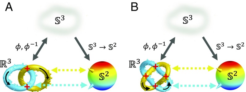
Starting from Gauss, Kelvin, and Maxwell (9), knots in fields fascinated physicists and mathematicians alike. By introducing the celebrated Hopf fibration (10), Hopf demonstrated that, indeed, interlinked closed loops could be smoothly embedded in the 3D space (ℝ3). Localized in all three spatial dimensions, 3D topological Hopf solitons are physical realizations of topology of such fibrations, with each closed-loop region of space corresponding to a single distinct orientation of the field (9, 11–19). They attracted a great deal of theoretical interest (9, 11–19), although the challenge of their experimental realization persisted for decades, until the recent demonstrations in both LCs (4) and ferromagnetic colloidal fluids (8). Since the 3D solitons smoothly embed into the uniform far-field background, their smooth field configurations in space ℝ3 can be effectively “compactified” to a three-sphere , and the field topology is then characterized by the → maps (4, 8–10). Within the homotopy theory (9), the 3D solitons in the magnetization M(r) vector fields of magnets, with a 2D sphere as the ground-state manifold, belong to the third homotopy group π3() = ℤ. In nonpolar LCs, the ground-state manifold is a sphere with antipodal points identified, /ℤ2, so that the corresponding solitons are labeled as π3(/ℤ2) = ℤ (4). For a direct comparison of electric and magnetic switching, we vectorize n(r) in this work (4), although we also discuss the implications of LC’s nonpolar nature. Topologically distinct 3D solitons are characterized by integers dubbed “Hopf indices” Q ∈ ℤ (4, 8, 9) and have closed-loop preimages corresponding to all points of the ground-state manifold, with each two distinct preimages interlinked Q times (Fig. 1) (4, 8). What happens as an external magnetic H or electric E field is applied, forcing M(r) and n(r) to realign? How can H and E potentially switch Q, say, transforming the soliton with preimages linked once (Fig. 1A) into the one with preimages linked twice (Fig. 1B)? In this work, we study topological transformations of 3D solitons in chiral nematic LC (4) and in its ferromagnetic colloidal counterpart (8) in response to external fields. A combination of direct 3D nonlinear optical imaging and numerical modeling through minimization of free energy reveals 3D spatial patterns of M(r) and n(r) and preimages. Numerical integration, which follows an approach originally developed by Whitehead (20), and analysis of preimage linking reveal Q and its changes during the topological transformations. These findings uncover the richness of static Hopf solitons and how they transform in response to external stimuli.
Fig. 1.
Topological solitons. Preimages in ℝ3 (and ) correspond to distinct points on form Hopf () (A) and Solomon links () (B) with linking numbers matching their Q = 1 (A) and Q = 2 (B) Hopf indices. Since the direct (ϕ) and inverse (ϕ−1) stereographic projections relate smooth configurations in and ℝ3 when embedded within the uniform n0 and M0, these solitons are characterized by the → maps, the third homotopy group π3() = ℤ and Q ∈ ℤ. Black arrows indicate circulation directions, crossing signs are marked in red color, and the colors of preimages match that of the corresponding points on .
Results
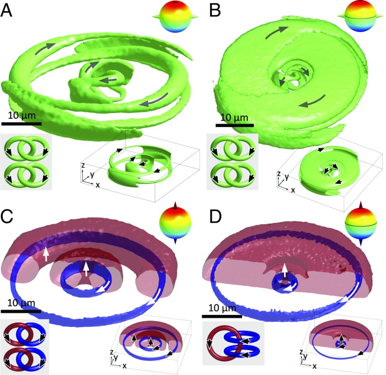
To explore how 3D topological solitons with different linking of preimages transform one to another in response to external fields, we fix the alignments of the far-field director n0 and magnetization M0, which assures compactification of ℝ3 to . In experiments, this is done by photo-polymerizing the exterior-of-torus preimage of the north pole of . Numerically, we model solitons for the same uniform far-field exterior n0 and M0 of the solitons by minimizing the free energy of LCs (4) and colloidal ferromagnets (8) so that experimental and computer-simulated preimages can be compared, as in the examples in Fig. 2. The Hopf index Q is determined based on its geometric interpretation as the linking number of preimages of any two distinct points on (Fig. 1) (4, 8). Although different conventions have been used (4, 8, 9, 20–24), here we use the right-hand rule convention to determine the sign of Q as that of the linking number between closed loops with consistently determined circulations. In addition, Q is computed by integrating a topological charge density in either or ℝ3 (20–24). For a solitonic unit vector field n(r) in ℝ3 with a uniform far-field n0,
| [1] |
where , is the Levi–Civita symbol, Ai is defined as , index summation convention is used, and details of calculation are presented in Supporting Information. For all studied topological solitons, the Hopf indices obtained as the preimage linking numbers and via integration of the topological charge density match up to numerical errors (Table S1).
Fig. 2.
Comparison of experimental and computer-simulated preimages of Q = −2 solitons. Experimentally reconstructed preimages of antipodal points on the equator (A and B) and at the poles (C and D) for a soliton at U = 0, corresponding to Fig. 3A (A and C), and at U = 3.6 V, corresponding to Fig. 3B (B and D). The computer-simulated counterparts of these preimages are shown in Lower Right Insets. The schematics of links are shown in Lower Left Insets, and the points on are depicted in Upper Right Insets.
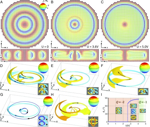
We first realize a Q = −2 soliton in a chiral LC with negative dielectric anisotropy Δε (Fig. 3A), which comprises two elementary Q = −1 solitons arranged coaxially (4). The preimage of each point on is composed of two separate unlinked loops, where we label the individual preimages using the standard Alexander–Briggs notation with C representing the minimal number of crossings within closed loops forming a knot or link, i giving the order among all knots with the same crossing number, and N indicating the number of components (9). The Q = −2 index of this composite soliton is confirmed by analyzing how preimages of all pairs of distinct points on interlink (Fig. 3D) and via numerical integration (Table S1). In applied field E, due to negative Δε, n(r) tends to align orthogonally to E, smoothly morphing the constituent elementary coaxial hopfions into a single solitonic structure, which is shown in Fig. 3B for an applied voltage U = 3.6 V. Numerically calculated Q = −2 and the same linking number of preimages within this hopfion remain unchanged up to U = 4.2 V. However, above U = 2.6 V, we find a boundary line on , which is characterized by a critical polar angle θ = θc in spherical coordinates (measured with respect to the north pole orientation) and separates two subspaces: (i) single-loop () preimages of points at θ < θc and (ii) preimages of points at θ > θc in the form of two separate unlinked loops (). Although there are different geometric configurations of closed loops, depending on U and the selection of points on relative to θc, they have the same net linking number −2 up to U = 4.2 V, consistent with the numerically calculated Q (Fig. 3 E, G, and H, Movie S1, and Table S1). Above U = 4.2 V, the interplay of the elastic and electric field coupling terms of free energy causes the structure to transform discontinuously as the topological transition from a soliton with Q = −2 to the one with Q = −1 takes place through a series of short-lived singular transient states (Fig. 3C). The high-voltage soliton has distinct preimages forming a Hopf link with linking number −1, in agreement with the numerically calculated Hopf index (Fig. 3 C and F and Table S1). The stable solitons show dependencies of Q and θc on U (Fig. 3I). The jump of θc from 0° to 68° at U = 2.6 V corresponds to the transformation from two coaxially arranged elementary solitons to a soliton with more complex preimage linking, with θc vs. U increasing until the Q-changing discontinuous topological transformation happens at U = 4.2 V.
Fig. 3.
Electrically driven topological transformation of a soliton. (A–C) Computer-simulated cross-sections of the soliton at different U obtained in the plane orthogonal to n0 (Upper) and in the vertical plane containing n0 (Lower). The vector fields are shown with arrows colored according to the corresponding points on (A, Upper, Inset), and U is indicated for each structure. (D–H) The 3D preimages in ℝ3 of points on indicated as cones in the Upper Right Insets. (D and F) Correspond to the solitons shown in A and C, respectively, while E, G, and H correspond to B. The Lower Right Insets show schematics of the linking of preimages, with the signs of crossings marked in red. Arrows on preimages represent their consistently determined circulations. In D, preimages of distinct points on form a pair of Hopf links with a net linking number −2. In E, G, and H, a preimage can be a single loop () or two separate closed-loops (), depending on the location of corresponding points on , with different subspaces of separated by a boundary at θc = 85°; for all combinations of distinct points on , the total linking number is −2. In F, a preimage is a single loop, and the linking number is −1 for all pairs of distinct points on . For more details on the structure analyzed in B, E, G, and H, see Movie S1. (I) θc and Q of the soliton vs. U, with abrupt changes of θc at U = 2.6 V and Q at U = 4.2 V, as marked and shown using different background colors. Schematics of preimage linking within each voltage range are shown as Insets. Computer simulations were done for elastic constants of AMLC-0010 (Table S2) and d/p = 1.5.
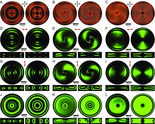
To compare theoretical and experimental solitonic field configurations under the same confinement and applied voltages, we computer-simulate polarizing optical micrographs and 3D nonlinear optical images for different polarizations of excitation light (Supporting Information). The excellent agreement between experimental and theoretical images, which are optical slices of ℝ3 of a sample with the soliton, unambiguously confirms the nature of topological transformation induced by electric switching (Fig. 4 and Movie S2). Furthermore, reconstructed experimental preimages also agree with their numerical counterparts (Fig. 2), providing insights into the transformations of n(r) that either maintain Q or change it, as well as the variation of θc with U. The examples of preimages of diametrically opposite points on the equator of reconstructed at different voltages (Fig. 2 A and B) reveal how preimages of a soliton shown in Fig. 3 A and B morph in shape without changing the topology of their linking while Q = −2 is conserved up to U = 4.2 V. A comparison of the corresponding theoretical and experimental preimages of the north pole of (Fig. 2 C and D) reveals how the shared far-field background n0 of a Q = −2 soliton composed of coaxially arranged elementary hopfions morphs in the applied field, so that the two separate tori defining the soliton’s exterior at U = 0 (Fig. 2C) morph into a single torus (Fig. 2D) without changing the net linking number and Q. The experimental and theoretical reconstructions of the north-pole preimages illustrate how, despite similarities in their topology, Hopf fibration and Hopf soliton differ geometrically (Fig. 2 C and D). The Hopf fibration uniformly fills ℝ3, with the fiber corresponding to the north pole of connected into the closed loop through infinity, whereas the topological Hopf soliton has most of the ℝ3 occupied by the preimage of the north pole of , except for the interior of the torus-shaped region of the soliton, within which all other preimages are smoothly packed (Fig. 2 C and D). Our observations also show how hopfions with different Q can interact to result in addition or subtraction of Hopf indices, depending on their relative signs.
Fig. 4.
Comparison of experimental and computer-simulated optical images of solitons shown in Fig. 3. The images in Left are obtained experimentally, and those in Right are computer-simulated. (A–C) Polarizing optical micrographs of solitons corresponding to Fig. 3 A–C, respectively. (D–L) Cross-sectional nonlinear optical images of solitons corresponding to structures in Fig. 3A (D, G, and J), Fig. 3B (E, H, and K), and Fig. 3C (F, I, and L), respectively. Upper images are midplane cross-sections orthogonal to n0, and Lower images are cross-sections parallel to n0 and passing through the central axes of the solitons. The polarization states of excitation light are linear in D–I, as marked at the top of the images, and are circular in J–L. The solitons are hosted in a partially polymerizable mixture based on AMLC-0010 (Table S2) in a cell with d/p ∼ 1.5.
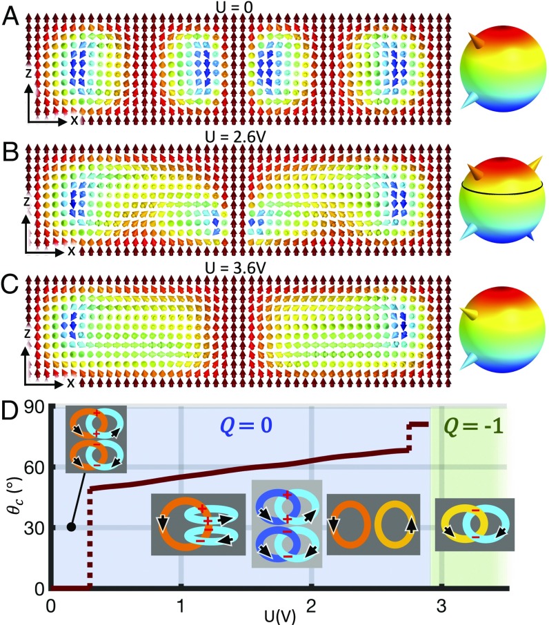
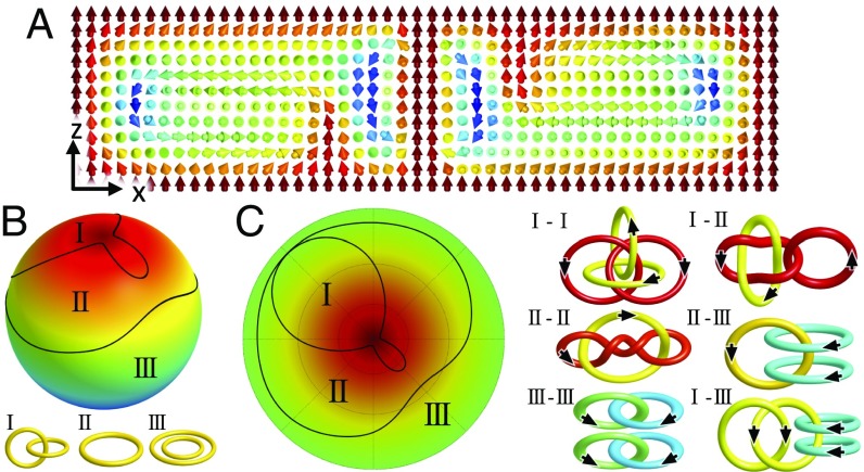
Solitonic structures with Q = 0 can also undergo electrically driven topological transformations while maintaining or changing Q (Fig. 5 and Figs. S1 and S2). For example, a stable Q = 0 soliton (Fig. 5A), comprising Q = 1 and Q = −1 elementary hopfions arranged coaxially, transforms continuously with increasing U, so that the coaxial Q = 1 and Q = −1 solitons start merging and partially annihilating at U > 0.2 V (Fig. 5 B–D). The ensuing boundary line separating different subspaces of at θc jumps from θc = 0 to θc = 49° at U = 0.3 V as partial annihilation starts and then increases continuously until U = 2.8 V, at which θc experiences another discontinuous jump and finally remains nearly constant at θc = 81° until the discontinuous transformation of the soliton at U = 2.9 V changes the Hopf index to Q = −1 (Fig. 5D). Fig. 5B shows the solitonic structure at U = 2.6 V, at which θc = 67.5° (Movie S3), whereas Fig. 5C depicts the soliton at U = 3.6 V. At intermediate voltages U = 0.2–2.9 V, preimages of single points on are single loops () at θ < θc or double unlinked loops () at θ > θc, yielding three distinct combinations of links between preimages, all with zero net linking number (Fig. 5D and Fig. S1). Stable topological solitons shown in Figs. 2–5 are all axially symmetric with respect to their central axis parallel to n0. However, the Q = −2 Hopf solitons can also be stabilized while having broken axial symmetry (Fig. 6A and Fig. S3). The corresponding map of single-point preimages of (Fig. 6 B and C) displays three subspaces, in which preimages take forms of a Hopf link (), a single loop (), or two separate loops (). The six links of preimages corresponding to distinct pairs of points within the three subspaces of reveal the same net linking number of −2. The boundary lines separate subspaces of with topologically different preimages, which can be understood as follows. Under continuous deformations, the preimages go through linking, unlinking, or merging between separate loops, thereby changing the topology of individual preimages for certain orientations and subspaces on (24). Interestingly, the topological boundaries induced by external fields in our study never go beyond the equator of with θc < 90°.
Fig. 5.
Electric switching of Hopf index from Q = 0 to Q = −1. (A–C) Computer-simulated cross-sections of the soliton in the plane orthogonal to n0 at different U. Right shows and points (depicted as cones) corresponding to the preimages provided in D, Insets. For more details on the structure shown in B, see Movie S3. (D) Critical polar angle θc and Q of the soliton vs. U, with abrupt changes of θc at U = 0.3 and 2.8 V and the jump of Q at U = 2.9 V, as marked and shown with different background colors. Schematics of preimage linking within each voltage range are shown as Insets, with the consistently determined circulations shown by black arrows and the signs of crossings marked in red. Computer simulations are based on elastic constants of AMLC-0010 (Table S2) and d/p = 1.35.
Fig. 6.
A Q = −2 soliton with broken axial symmetry. (A) Cross-section of the soliton in the plane parallel to n0 passing through its center. (B) The ground-state manifold divided into three subspaces (I, II, and III) by the black boundary lines, with the corresponding distinct types of preimages of single points in each subspace shown in Lower. (C) Stereographic projection of the northern hemisphere of (Left) and six possible combinations of links between distinct preimages (Right), all with linking number of −2. Computer simulations were performed for U = 4.0 V, elastic constants of AMLC-0010, and d/p = 1.5.
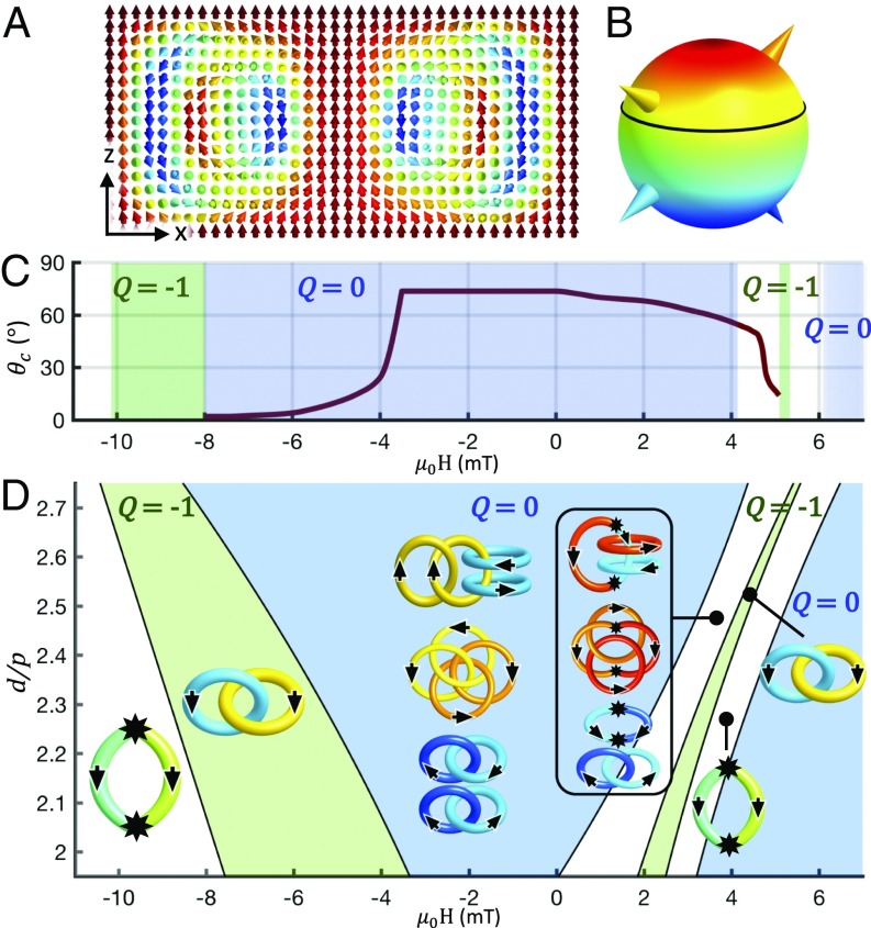
Magnetic fields also cause topological transformation of solitons, which in conventional nonpolar LCs is due to the diamagnetic coupling between n and H, similar to the dielectric response to E discussed above. However, magnetic switching of ferromagnetic colloidal LCs is polar in nature (5–8), so that the response of magnetization M(r) in these systems to H and −H is very different, further enriching our ability of inducing transformations of solitons. To provide an example, we start from a soliton with complex linking of preimages but the net Q = 0, shown in Fig. 7 A and B at no fields. The external field H, applied along M0, drives the soliton through a series of continuous and discontinuous deformations by coupling linearly to M(r) (Fig. 7 C and D and Fig. S4). Depending on the sample thickness to pitch ratio d/p and the applied field, the ground state manifold for these structures can be split into two subspaces, separated by a boundary at a critical polar angle θc. As an example, Fig. 7C shows the dependence of θc on H at d/p = 2.7. We construct a structural phase diagram for the stabilized soliton in the coordinates of d/p and the magnitude of applied magnetic field (Fig. 7D). The diagram encompasses a wealth of knotted field configurations, including the nonsingular Q = 0 solitons with complex linking dependent on d/p and H and an elementary Q = −1 soliton, as well as structures dubbed “torons” in which solitons are accompanied by singular point defects (4, 25). The distinct types of preimage linking are shown in Fig. 7 D, Insets, with the details of their reconstruction based on 3D field configurations presented in Fig. S4 and Movie S4. Our system is rather insensitive to the Earth’s magnetic field ∼0.05 mT (Fig. 7), but even this Earth’s field could potentially morph hopfions at higher concentrations of magnetic nanoplates (5–7).
Fig. 7.
Stability of solitonic structures vs. d/p and H. (A) Computer-simulated cross-section of a stable axially symmetric Q = 0 soliton at H = 0 and d/p = 2.7. The cross-section is parallel to n0 and passes through the soliton’s symmetry axis. For more details on preimages of this soliton, see Movie S4. (B) Ground-state manifold with four points (depicted by colored cones) corresponding to preimages of the same color schematically shown in D, Insets. Black circle shows the boundary line at θc = 73.5° separating subspaces of with different types of individual preimages [double unlinked loops () for θ > θc and a Hopf link of closed loops () for θ < θc]. (C) θc and Q vs. μ0H at d/p = 2.7. Q values are indicated atop of the colored regions of constant Q = −1 (green regions) and Q = 0 (blue regions). Singular point defects accompany the nonsingular solitons, forming torons, within the white uncolored regions. The critical angle is almost unaltered when H is antiparallel to M0 and while its strength increases up to μ0H = −3.5 mT, at which θc starts to drop rapidly to zero. At μ0H = −8 mT, a discontinuous transformation changes Q from 0 to −1. At fields H antiparallel to M0 with μ0H = −10.1 mT and stronger, the field configuration is singular and resembles the structure of an elementary toron (25). The critical angle θc drops gradually with increasing the field strength for H parallel to M0, and self-compensating singular point defects emerge starting at μ0H = 4.1 mT, yielding the axially symmetric field configuration of a toron with 3π twist from its central axis to the far field periphery, dubbed “3π toron” (4), with a critical polar angle on across which preimages have different topologies (4). At μ0H = 5.2 mT, a smooth field configuration is recovered, and an elementary hopfion of Q = −1 is stabilized. At larger μ0H, the field becomes singular again, and elementary torons form (4, 25). The field configuration becomes monodomain uniform starting at 6.1 mT. μ0H is defined as positive when H is parallel to M0 and negative when antiparallel to it. (D) Stability diagram of the solitons vs. d/p and the magnetic field strength μ0H. Insets depict the diverse topology of two-point preimages and their links for a family of hopfions with Q = 0, −1, and two different types of torons that are stabilized in different regions of the diagram. The black filled stars atop some of the linking diagrams indicate the locations of point singularities at which individual preimages can terminate. Computer simulations were performed for material parameters of the chiral ferromagnetic LC based on the nematic host ZLI-2806 doped with ferromagnetic nanoplates and for the cell geometry with M0 fixed at both the confining substrates and on the cylindrical region of the far-field periphery of the soliton. The host material was formed by dispersing nanoplates, each with a magnetic moment of 1.2 × 10⁻¹⁷ A⋅m2, in a chiral LC at number density of 10 μm−3.
Our findings show that different types of preimages of points on can not only coexist within the same knot soliton [compare, for example, the Hopf link of two closed loops (), a single loop (), and two unlinked loops () in Fig. 6B] (4), smoothly embedding within a localized volume in ℝ3, but also that they can be reversibly transformed one into another by using external fields while remaining nonsingular. For example, this is manifested by splitting of with preimages in the form of two unlinked rings at low U (Fig. 3 A, D, and I) into two subspaces separated by the θ = θc boundary line on at U > 2.6 V (Fig. 3 B, E, and G–I), where preimages take forms of a single loop or two unlinked loops, depending on θ relative to θc. The combination of experiments and modeling allows us to analyze these transformations both in terms of preimages of points and directly as continuous patterns of n(r) and M(r), revealing that the net linking number between preimages of a single soliton is conserved and consistent with numerically calculated Q. This complexity of knot solitons is characteristic for both nonpolar and polar fields, as demonstrated by using n(r) and M(r), but many subtle issues become apparent when preimages are analyzed in nonpolar n(r) and also for the /ℤ2 ground state manifold (Table S1). For example, the linking number of preimages of two distinct points on /ℤ2 for a nonpolar n(r) is exactly four times that of preimages of two points on for its vectorized counterpart, due to the fact that n and −n are identified as a single point on /ℤ2 in a nonpolar field (Table S1). Although the reversal of the vectorization direction of nonpolar n(r) does not alter the sign of Q, the reversal of the equilibrium handedness of the host LC and ferromagnet negates the sign of Q of the Hopf solitons (to enable a direct comparison, all solitonic structures are presented for the right-handed host media).
To conclude, we have demonstrated that Hopf solitons can continuously evolve to display very different preimages, say, with the transformation of two separate preimage loops into single ones, while preserving the Hopf index value. We also illustrated how, at different conditions, these solitons display discontinuous transformations associated with abrupt changes of Hopf indices between different integers. The experimental platform we have developed may lead to technological applications building on the particle-like nature of topological solitons, say, in multistable low-power information displays and in data storage. Since both chiral LCs and colloidal ferromagnets are optically birefringent, different Hopf index values can be associated with optical signatures, such as polarization rotation, phase retardation, and light transmission when the sample is placed between polarizers, which could potentially enrich the wealth of current electro-optic applications of these soft matter systems. While realization of stable hopfions in other physical systems remains a challenge, our ability of transforming such solitonic configurations by weak external fields will make them a testbed for physical theories involving such solitons and also the mathematical knot theory itself.
Materials and Methods
Our methods of numerical minimization of free energy of chiral LCs and colloidal ferromagnets, as well as the construction of preimages (4, 8) based on experimental nonlinear optical images (25, 26) and numerical field configurations, are described in SI Materials and Methods. To realize and switch hopfions, a polymerizable nematic mixture of AMLC-0010 (75%; AlphaMicron Inc.), E7 (4%; EM Chemicals), RM-82 (6%; Merck), RM-257 (14%; Merck), and photoinitiator Irgacure 369 (1%; Sigma-Aldrich) is doped with right-handed chiral dopants CB-15 (EM Chemicals) or ZLI-811 (EM Chemicals) at a weight fraction to define the helicoidal pitch p of the partially polymerizable chiral LC, where is the helical twisting power of the dopant (Table S2). The samples are prepared by sandwiching these mixtures between indium–tin–oxide-coated glass substrates. The colloidal chiral ferromagnets are prepared by using identical procedures, but additionally utilize small volume fractions of barium hexaferrite nanoplates, which are dispersed in the LC mixtures (8). To set strong perpendicular boundary conditions for the director and magnetization fields, the substrates are treated with polyimide SE1211 (Nissan Chemicals) by spin-coating at 2,700 rpm for 30 s and then baking 5 min at 90 °C, followed by 1 h at 180 °C. Cells with thickness d = 10 μm are assembled by using glass spacers. The solitons are generated with holographic optical tweezers, either by local laser-induced heating of the LC to the isotropic phase and subsequent temperature quenching or by moving the laser focus of the holographic optical trap along a circular trajectory within the cell midplane (4). The latter method allows for the preselected generation of Q = 1 or Q = −1 elementary solitons via controlling the winding direction and depth of the circular laser beam motion. The uniform n0 and M0 in the exterior-of-torus preimages of the north pole of are set through strong perpendicular boundary conditions on the confining substrates and two-photon polymerization of the partially polymerizable mixtures. This involves photo-polymerizing a cylindrical region exterior to the soliton and a pillar-like region going through the central axis, yielding “doughnut-like” patterned boundary conditions. In the polymerized regions, the diacrylate monomers cross-link so that the orientations of uniform n0 and M0 are “frozen” and stay unchanged in applied fields, setting boundary conditions for n(r) and M(r) at the interface between polymerized and unpolymerized regions. The experimental material parameters used in modeling are summarized in Table S2.
Supplementary Material
Acknowledgments
We thank H. Sohn and Y. Yuan for discussions. This work was supported by US Department of Energy, Office of Basic Energy Sciences, Division of Materials Sciences and Engineering Award ER46921. This work utilized a supercomputer supported by National Science Foundation Awards ACI-1532235 and ACI-1532236.
Footnotes
The authors declare no conflict of interest.
This article is a PNAS Direct Submission.
This article contains supporting information online at www.pnas.org/lookup/suppl/doi:10.1073/pnas.1716887115/-/DCSupplemental.
References
- 1.de Gennes PG, Prost J. The Physics of Liquid Crystals. Clarendon; Oxford: 1995. [Google Scholar]
- 2.Chaikin PM, Lubensky TC. Principles of Condensed Matter Physics. Cambridge Univ Press; Cambridge, UK: 2000. [Google Scholar]
- 3.Cheng KT. Liquid crystal display—Present status and emerging technology. In: Lee CC, editor. The Current Trends of Optics and Photonics. Springer; Dordrecht, The Netherlands: 2015. pp. 289–307. [Google Scholar]
- 4.Ackerman PJ, Smalyukh II. Diversity of knot solitons in liquid crystals manifested by linking of preimages in torons and hopfions. Phys Rev X. 2017;7:011006. [Google Scholar]
- 5.Mertelj A, Lisjak D, Drofenik M, Copič M. Ferromagnetism in suspensions of magnetic platelets in liquid crystal. Nature. 2013;504:237–241. doi: 10.1038/nature12863. [DOI] [PubMed] [Google Scholar]
- 6.Liu Q, Ackerman PJ, Lubensky TC, Smalyukh II. Biaxial ferromagnetic liquid crystal colloids. Proc Natl Acad Sci USA. 2016;113:10479–10484. doi: 10.1073/pnas.1601235113. [DOI] [PMC free article] [PubMed] [Google Scholar]
- 7.Zhang Q, Ackerman PJ, Liu Q, Smalyukh II. Ferromagnetic switching of knotted vector fields in liquid crystal colloids. Phys Rev Lett. 2015;115:097802. doi: 10.1103/PhysRevLett.115.097802. [DOI] [PubMed] [Google Scholar]
- 8.Ackerman PJ, Smalyukh II. Static 3D knotted solitons in fluid chiral ferromagnets and colloids. Nat Mater. 2017;16:426–432. doi: 10.1038/nmat4826. [DOI] [PubMed] [Google Scholar]
- 9.Manton N, Sutcliffe P. Topological Solitons. Cambridge Univ Press; Cambridge, UK: 2004. [Google Scholar]
- 10.Hopf H. Über die abbildungen der dreidimensionalen sphäre auf die kugelfläche. Math Ann. 1931;104:637–665. [Google Scholar]
- 11.Faddeev L, Niemi AJ. Stable knot-like structures in classical field theory. Nature. 1997;387:58–61. [Google Scholar]
- 12.Battye RA, Sutcliffe PM. Knots as stable soliton solutions in a three-dimensional classical field theory. Phys Rev Lett. 1998;81:4798–4801. [Google Scholar]
- 13.Gladikowski J, Hellmund M. Static solitons with nonzero Hopf number. Phys Rev D Part Fields. 1997;56:5194. [Google Scholar]
- 14.Hall DS, et al. Tying quantum knots. Nat Phys. 2016;12:478–483. [Google Scholar]
- 15.Bolognesi S, Shifman M. Hopf Skyrmion in QCD with adjoint quarks. Phys Rev D. 2007;75:065020. [Google Scholar]
- 16.Gorsky A, Shifman M, Yung A. Revisiting the Faddeev-Skyrme model and Hopf solitons. Phys Rev D. 2013;88:045026. [Google Scholar]
- 17.Acus A, Norvaišas E, Shnir Y. Hopfions interaction from the viewpoint of the product ansatz. Phys Lett B. 2014;733:15–20. [Google Scholar]
- 18.Thompson A, Wickes A, Swearngin J, Bouwmeester D. Classification of electromagnetic and gravitational hopfions by algebraic type. J Phys A. 2015;48:205202. [Google Scholar]
- 19.Kobayashi M, Nitta M. Torus knots as Hopfions. Phys Lett B. 2014;728:314–318. [Google Scholar]
- 20.Whitehead JHC. An expression of Hopf’s invariant as an integral. Proc Natl Acad Sci USA. 1947;33:117–123. doi: 10.1073/pnas.33.5.117. [DOI] [PMC free article] [PubMed] [Google Scholar]
- 21.Sutcliffe P. Knots in the Skyrme–Faddeev model. Proc R Soc London Ser A. 2007;463:3001–3020. [Google Scholar]
- 22.Hietarinta J, Palmu J, Jäykkä J, Pakkanen P. Scattering of knotted vortices (Hopfions) in the Faddeev–Skyrme model. New J Phys. 2012;14:013013. [Google Scholar]
- 23.Bott R, Tu LW. Differential Forms in Algebraic Topology. Springer; Berlin: 1982. [Google Scholar]
- 24.Hietarinta J, Jäykkä J, Salo P. Dynamics of vortices and knots in Faddeev’s model. In: Ferreira A, Gomes F, Zimerman H, editors. Workshop on Integrable Theories, Solitons and Duality Proceeding of Science (SISSA) PoS(unesp2002)017. Proceedings of Science; Trieste, Italy: 2002. [Google Scholar]
- 25.Smalyukh II, Lansac Y, Clark NA, Trivedi RP. Three-dimensional structure and multistable optical switching of triple-twisted particle-like excitations in anisotropic fluids. Nat Mater. 2010;9:139–145. doi: 10.1038/nmat2592. [DOI] [PubMed] [Google Scholar]
- 26.Martinez A, et al. Mutually tangled colloidal knots and induced defect loops in nematic fields. Nat Mater. 2014;13:258–263. doi: 10.1038/nmat3840. [DOI] [PubMed] [Google Scholar]
Associated Data
This section collects any data citations, data availability statements, or supplementary materials included in this article.


