Abstract
IMPORTANCE
Computational modeling can be used to mimic the forces acting on the nasal framework that lead to the inverted-V deformity (IVD) after surgery and potentially determine long-range outcomes.
OBJECTIVE
To demonstrate the use of the finite element method (FEM) to predict the formation of the IVD after separation of the upper lateral cartilages (ULCs) from the nasal septum.
DESIGN, SETTING, AND PARTICIPANTS
A computer model of a nose was derived from human computed tomographic data. The septum and upper and lower lateral cartilages were designed to fit within the soft-tissue envelope using computer-aided design software. Mechanical properties were obtained from the literature. The 3 simulations created included (1) partial fusion of the ULCs to the septum, (2) separation of the ULCs from the septum, and (3) a fully connected model to serve as a control. Forces caused by wound healing were prescribed at the junction of the disarticulated ULCs and septum. Using FEM software, equilibrium stress and strain were calculated. Displacement of the soft tissue along the nasal dorsum was measured and evaluated for evidence of morphologic change consistent with the IVD.
MAIN OUTCOME AND MEASURES
Morphologic changes on the computer models in response to each simulation.
RESULTS
When a posteroinferior force vector was applied along the nasal dorsum, the areas of highest stress were along the medial edge of the ULCs and at the junction of the ULCs and the nasal bones. With full detachment of ULCs and the dorsal septum, the characteristic IVD was observed. Both separation FEMs produced a peak depression of 0.3 mm along the nasal dorsum.
CONCLUSIONS AND RELEVANCE
The FEM can be used to simulate the long-term structural complications of a surgical maneuver in rhinoplasty, such as the IVD. When applied to other rhinoplasty maneuvers, the use of FEMs may be useful to simulate the long-term outcomes, particularly when long-term clinical results are not available. In the future, use of FEMs may simulate rhinoplasty results beyond simply morphing the outer contours of the nose and allow estimation of potentially long-term clinical outcomes that may not be readily apparent.
LEVEL OF EVIDENCE
NA.
During the past 2 decades, medicine has increasingly focused on developing patient-specific outcomes and individually tailored therapies. This theme has been interpreted within the context of molecular-based therapies but aptly applies to surgery, where operations need to be tailored to each patient’s anatomy. In rhinoplasty, preoperative photography and digital image processing are the first steps in this process and have enhanced surgical planning and improved surgical outcomes for patients. Software packages designed to process and morph digital images are now a vital component of the consultation process, preoperative analysis, and surgical planning; however, they are limited in that they manipulate only the surface contours of the patient’s nose. Contemporary rhinoplasty is directed as much at the nasal framework as theskin–soft-tissue envelope, and understanding how this structure responds to static and dynamic forces during short- and long-term intervals affords the key to successful outcomes.
Experience has demonstrated that the long-term aesthetic and functional outcomes of rhinoplasty may not be known for years because the forces acting on the tissues are minute and changes occur gradually as a consequence of the forces generated by tissue remodeling, airflow (dynamic pressure drops), and gravity. Predicting long-term changes is important, particularly given the sharp rise in new surgical techniques and procedures. Fifty years ago, pinched tips, alar retraction, stenotic vestibules, and other adverse outcomes were not known or predicted as consequences of what was accepted as standard-of-care surgery, and several decades and a generation of surgeons, each on their own learning curve, were required to understand the root causes of these deformities. Gaining insight into and possibly predicting the consequences of new and emerging rhinoplasty techniques can help to design better operations that create stable long-term outcomes.
Despite advances in technology, an exponential increase in peer-reviewed articles on rhinoplasty surgery, and a growing armamentarium of new techniques and maneuvers, revision rates for rhinoplasty have remained relatively unchanged during the past 50 years, ranging from 5% to 15%.1 Although the reasons for this lack of change are multifactorial, understanding how to alter the shape of the nose requires more than an understanding of surface contour management.2 Understanding how cartilage preservation, grafting, and wound healing alter static and dynamic nasal mechanics during short- and long-term intervals is extremely important. For each surgeon, this knowledge is generally gained via trial and error after many years, if not decades. Predicting how steady-state shape evolves in a postrhinoplasty nose is clearly challenging, but some tools are now available to accomplish at least part of this task.
This study examines whether finite element modeling (FEM) may be used to predict how separation of the upper lateral cartilages (ULCs) from the nasal septum leads to the formation of the inverted-V deformity (IVD). Finite element modeling is a numerical technique aimed at mathematically subdividing a complex structure or process into simpler parts containing the material properties of that entity. A wide variety of phenomena, including heat transfer, fluid dynamics, and mechanical structures can be described by this method. Dividing the whole structure into a collection of subdomains allows one to highlight regions with high levels of stress or displacements. The particular long-term complication of IVD was selected because we have a broad clinical consensus on the root cause of its formation.3,4 The IVD has aesthetic and functional implications. Hence, studying the IVD provides a means to validate the use of the FEM as a potential tool to estimate long-term steady-state outcomes of various rhinoplasty maneuvers, especially where the outcomes are less clear cut or obvious.
The IVD commonly results from dorsal hump reduction with separation of the attachments between the ULCs and the dorsal septum (DS) in the absence of midvault reconstruction. In this study, we simulate separation of the ULCs from the DS and apply forces along the dorsum that lead to contour changes mimicking the IVD.
Methods
Construction of Nasal Models
The process of building the FEM has been described previously,5 and we will review it briefly herein. A high-resolution, maxillofacial, computed tomographic scan of a single patient was used to generate the soft-tissue and bone surface reconstructions of the nasal model using medical image processing software (Mimics; Materialise). Cartilage structures were built and custom fit within the soft-tissue envelope using 3-dimensional (3-D) design software (3ds Studio Max; Autodesk) and imported into Mimics. Attachments at the scroll region, between the ULCs and DS, and between the medial crura and the caudal septum were created in Mimics. Two experimental models were created in this study by changing the degree of separation of the ULCs and DS using the 3-D editing tool in Mimics to replace cartilage voxels manually along the ULC border with soft-tissue voxels. A nasal model with the ULCs and DS fully separated and another model with the ULCs and DS partially separated were created along with a control model of full cartilaginous connection between the ULCs and DS. This study was performed in accordance with the guidelines of the institutional review board at the University of California, Irvine.
Mesh generation of tetrahedral elements with a maximum edge length of 2 mm was performed in triangulated software (3-matic; Materialise) and exported as a Nastran format. An oblique view of the FEMs with and without attachments between the ULCs and DS are shown in Figure 1 with the soft tissue rendered slightly transparent.
Figure 1. Finite Element Model of a Normal Human Nose.
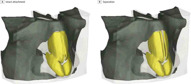
Models with intact attachments and separation of the upper lateral cartilages and dorsal septum were created in medical image-processing software (Mimecs; Materialise).
Simulation of the IVD
The FEM was imported into the finite element analysis software (Abaqus; Dassault Systèmes Simulia Corp), and its components were assigned material properties, which were taken from the literature.5–9 Physical properties of skin, including the mass density and Poisson ratio, were approximated and applied to the soft-tissue envelope (Young modulus, 0.5 MPa; density, 980 kg/m3; and Poisson ratio, 0.33). The mechanical properties of articular cartilage were used in this model because of the sparse information and limited quality of the data for the mechanical properties of facial cartilage (Young modulus, 0.8 MPa; density, 1080 kg/m3; and Poisson ratio, 0.15). Bone was assigned cortical bone properties (Young modulus, 15 GPa; density, 1900 kg/m3; and Poisson ratio, 0.22).
To simulate the IVD, the nasal bones were held fixed and a normal force was applied to the medial portion of the ULCs as indicated in Figure 2. A total force of 5 N was prescribed to each side of the ULCs in all models. Selection of a force value of 5 N was not arbitrary but was derived from a trial-and-error process in preliminary simulations, with the end point being creation of a dorsal deformation consistent with what is observed clinically. The rest of the cartilage and overlying soft tissue was free to move. A model with the DS and ULCs fully connected was also subjected to the same forces to serve as a control.
Figure 2. Application of Pressure.
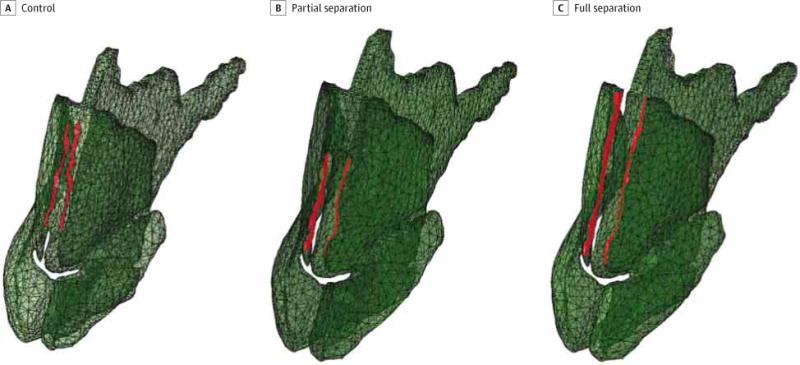
Red indicates areas where pressure was applied to the model.
We calculated the resultant von Mises stress and strain of each model. von Mises stress is a scalar value that combines the normal and shear stresses for each element under a complex 3-D loading condition.10 In subsequent text, when the term stress is used, we are referring to the von Mises values. The key load-bearing and displaced structures within the nose were identified by examining results from the computer simulations.
Results
Stress Distribution Along the Nasal Dorsum
The steady-state stresses produced as a result of a 5-N force applied to the medial portion of the ULCs are concentrated along the anterior septum and ULCs as illustrated in Figure 3. A partial separation between the ULCs and septum produced the greatest stresses in separated regions between the septum and ULC (Figure 3A). The peak stress in this model was 242 kPa. In contrast, a full separation between the ULCs and septum produced similar results, with most of the stresses concentrated between the septum and ULCs. However, the peak stresses in this model were located at the superior portion of the right ULC at the junction with the nasal bone (Figure 3B) and had a value of 249 kPa. The model with partial separation contained 361 753 tetrahedral elements, and the model with full separation between the ULCs and septum contained 362 849 elements. The control model, by comparison, had a lower peak stress of 178 kPa at the medial DS, and its surface plot indicated no stress using the same scale. Thus, partial or full separation of the ULCs from the septum resulted in 36% to 40% more stress along the DS.
Figure 3. Surface Plot of von Mises Stresses on the Nasal Cartilages.
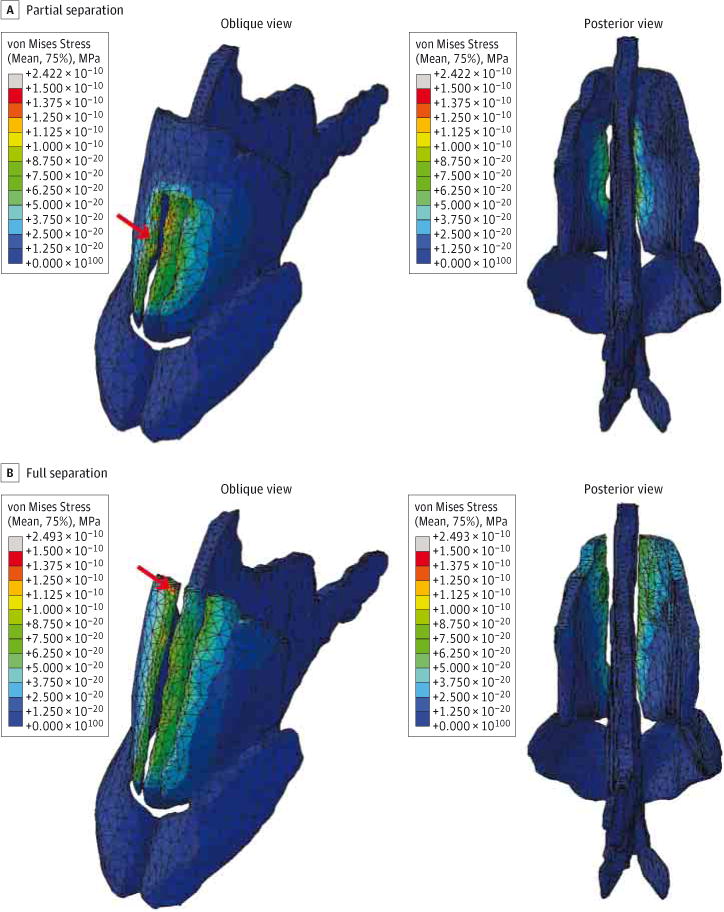
Stress values (in megapascals) are plotted on a color map scale where deep red indicates areas of highest stress and dark blue indicates no stress. Red arrows indicate the areas of peak stress.
Displacement Along the Nasal Dorsum
Displacement produced by the applied forces for the partially separated model and fully separated model is shown in Figure 4 and Figure 5, respectively. Although bone and skin components of the model were included in the simulation, they were made invisible in these figures to highlight the displacement of the cartilage (Figure 4B and Figure 5B). Both models predict a slight displacement (saddling) up to 0.3 mm along the nasal dorsum in the areas of highest stress distribution. The displacement profile along the nasal dorsum (eFigure in the Supplement) was different between models. The nasal model with partial connectivity between the septum and ULCs predicted a depression of the dorsum that was sharper and concentrated toward the bottom half of the nose. In contrast, the model with full separation of the ULCs and septum predicted a depression of the dorsum that was broader and concentrated toward the middle of the nose. The control model exhibited negligible displacement as expected, with a peak value of 1.32 μm identified at the medial nasal dorsum.
Figure 4. Surface Displacement Plots With Partial Disarticulation of the Upper Lateral Cartilages and Dorsal Septum.
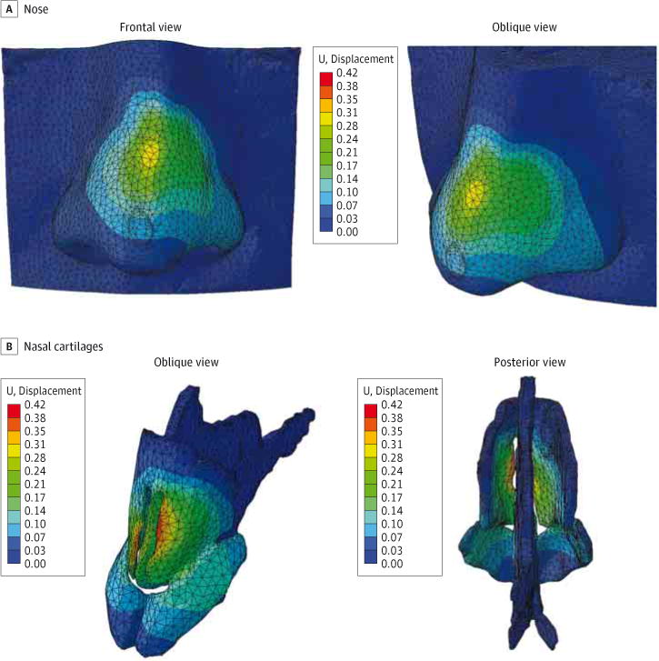
The finite element model shows partial disarticulation between the dorsal septum and upper lateral cartilages. Color map scale indicates magnitude of displacement.
Figure 5. Surface Displacement Plots With Full Disarticulation.
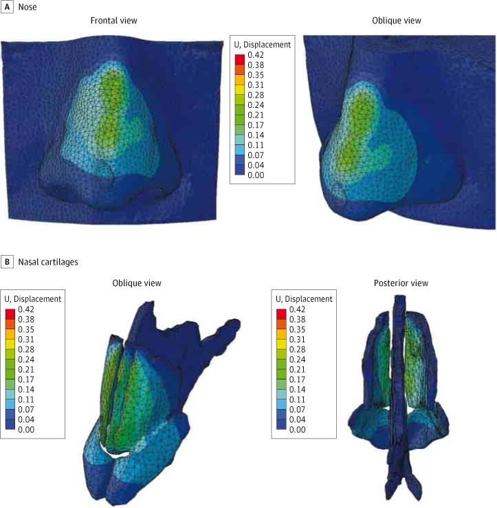
The finite element model shows full disarticulation between the dorsal septum and upper lateral cartilages. Color map scale indicates magnitude of displacement.
Discussion
An FEM consists of multiple interacting minute elements, each of which is assigned specific material properties. Once a model of a mechanical structure is created, it can be manipulated to determine how it will respond to forces that are applied to it. No single commercial product is designed today without FEM, and the cost of this software and computational power is now extremely low. Calculations that a decade ago required a supercomputer can now be performed on a laptop.
Simulation of the IVD was achieved by applying a posteroinferior force vector to the medial surface of the ULCs along the original junction with the DS. As a result, we are able to emulate the tissue remodeling process that occurs in response to the forces of gravity and scar contraction over time.
In orthopedics, the FEM is used to design joint prostheses. Within the field of head and neck surgery, the FEM has been used to describe middle ear mechanics and how the tympanic membrane and ossicles amplify and transduce sound waves.11–13 With respect to nasal mechanics, several authors14–16 have examined an isolated L-strut using an FEM and described the stress distribution in response to forces along the caudal septum and DS, explaining rigorously what is well known empirically–that leaving a 10- to 15-mm L-strut is necessary for structural stability of the nose. Previous work5,17 expanded on these early FEMs to develop a comprehensive 3-D FEM of the nose with soft-tissue, cartilage, and bony components derived from computed tomographic data. That model was used to examine nasal tip palpation, a common element of the physical examination, and described how the forces of tip depression are distributed across the cartilaginous support structures of the nose.5,17 The present results demonstrate an FEM simulating the long-term structural results of a surgical maneuver in rhinoplasty.18
The factors leading to the IVD are clinically well understood.4,19 The underlying pathophysiologic factor is the disruption of the attachments between the ULCs and DS.20–22 The forces of gravity and the scar contraction and tissue remodeling process, while negligible at any given instant, can result in significant displacement when these forces persist for many years after surgery. In the model described herein, disarticulating the ULCs and DS without reconstruction results in 36% to 40% greater stress along the cephalic aspect of the DS compared with a control nose. Over time, this increased mechanical stress results in a collapse of the cartilages in this area, resulting in the characteristic IVD. Empirical evidence has shown that reconstruction of the ULC-DS attachments, most commonly with spreader grafts, can stabilize this area and prevent this collapse of tissue over time.23,24 Surgeons now anticipate and avoid the IVD by reestablishing the ULC-DS attachments and reconstructing the midvault.
Clinically, the IVD is associated with the posterior descent of the ULCs, creating traction forces or stresses at the junction of the ULCs and nasal bones (Figure 3). This process leads to accentuation of this otherwise smooth and congruent contour, resulting in a shadowing effect that creates the deformity. A more subtle deformity seen by the senior author (B.J.F.W.) on occasion in referred secondary cases is a subtle saddling along the dorsum that extends from the keystone region to the supratip. This study numerically demonstrates this more subtle finding associated with the IVD (eFigure in the Supplement), albeit likely overestimating its magnitude. The reasons for saddling in this subset of patients may be related to the lack of midvault reconstruction; however, the cause of such saddling is difficult to ascertain because the IVD is typically a late consequence, and operative reports and photographs from decades prior are frequently not available to the revision rhinoplasty surgeon.
In reality, an FEM can only calculate displacement for a given force in a mechanistic fashion. In contrast, wound healing involves the summation of very small forces acting continuously over decades. Modeling this process is exceptionally complex and, to the best of our knowledge, has only been attempted in relatively simple physiologic models and systems.25–27 Adapting such time-dependent structural change in viscoelastic tissues involving wound healing is well beyond the scope of this simulation or any other existing simulation. Even in the simplest clinical circumstances, the mechanics of wound healing remain poorly understood.
However, we know the steady-state results of wound healing in the nose after several decades, and, with respect to midvault instability, the long-term outcomes are very well defined. We have attempted to emulate the effects of wound healing to create structural changes that mimic the formation of the IVD. In practice, the force that we have applied to the ULCs and the DS would never occur under physiologic circumstances. However, empirically selecting forces in the appropriate direction can lead to the structural changes that we would expect from a nonreconstructed midvault. In this simulation, all the forces of wound healing and gravity are aggregated into a single set of vectors to create the same steady-state change that would occur in vivo over decades. Although this assumption is rather broad, it has allowed simulation of the IVD using an anatomically accurate model rooted in structural mechanics.
A key limitation of this study is that results obtained in FEMs are purely theoretical at this point and have yet to be validated in a physical model. In an analogous manner, nasal airflow has been studied using computational fluid dynamics for several years.28–31 The concept of virtual surgery is close to realization, with operations now being simulated with computers before being performed on patients.32 Turbinate and septal surgery simulations can be compared with actual surgical procedures on patients, and immediate nasal airflow outcomes can be validated. Obviously, studies that examine the long-term effects of structural rhinoplasty maneuvers require immense coordination and close follow-up over time.33 Projects are currently under way in our laboratory to develop a physical, 3-D model of the nose that can be used to begin validating the FEM.
At present, many rhinoplasty maneuvers are performed and developed for which surgeons do not have 30 or 40 years of postoperative follow-up data that adequately describe shape and structural stability over time. Manipulations, such as the lateral crural strut graft, alar rim graft, or caudal septal extension graft, seem stable, but we have no way to predict the very long-term consequences of these relatively new structural rhinoplasty maneuvers with accuracy, especially when performed not by expert surgeons but by the rank and file. The implication of this study is that an FEM may be used to model these operative maneuvers and provide some insight with respect to potential long-term outcomes. This conclusion, of course, depends on a reasonable estimate of where forces will act and in which direction. In the long term, incorporating FEM-derived simulations of surgery may evolve to become an important part of preoperative surgical planning and analysis.
As surgeons, we want to believe that structural stability improves and that long-term outcomes will be excellent; however, objective evidence to support many emerging rhinoplasty maneuvers is lacking. Modeling the effects of gravity and the tissue healing process over time can be used to anticipate the effects of various grafts and maneuvers as we look toward improving patient-specific outcomes. Moreover, by manipulating the cartilaginous and structural components rather than simply the skin contour, the surgeon eventually may be able to give patients a more accurate representation of the short- and long-term appearance of their nose after surgeryimproving the patient’s expectations of outcomes and the surgeon’s likelihood of achieving them. These forces emulate the effect of gravity and contraction from scar. The FEM successfully recreates the contour of an IVD and illustrates the potential use of this approach to predict long-term outcomes of new maneuvers in rhinoplasty.
Conclusions
Although digital image processing currently allows surgeons to visualize intended outcomes, the ability to prospectively evaluate the long-term effects of structural manipulations of the nasal framework is still elusive. Much of what is known about the long-term consequences of rhinoplasty maneuvers has been borne out of experience; without that experience, we cannot predict the effects of newer operative techniques. The FEM offers a sophisticated tool to simulate and examine the long-term outcomes of surgical maneuvers. In this study, a simulation of the long-term outcome of disruption of the ULC-DS junction was modeled successfully by a 5-N force on the anterior portion of each ULC. In the future, as newer surgical techniques are developed, the use of FEMs may facilitate simulation of rhinoplasty results beyond simply morphing the outer contours of the nose.
Supplementary Material
Acknowledgments
Funding/Support: This study was supported by grant R21DE019026-01A2 from the National Institutes of Health; by grant DR090349 from the US Department of Defense; and by grant UL1 TR000153 from the National Center for Advancing Translational Sciences.
Role of the Funder/Sponsor: The funding sources had no role in the design and conduct of the study; collection, management, analysis, and interpretation of the data; preparation, review, or approval of the manuscript; and decision to submit the manuscript for publication.
Footnotes
Supplemental content at jamafacialplasticsurgery.com
Author Contributions: Dr Tjoa and Mr Manuel had full access to all the data in the study and take responsibility for the integrity of the data and the accuracy of the data analysis.
Study concept and design: Tjoa, Manuel, Leary, Protsenko, Wong.
Acquisition, analysis, or interpretation of data: All authors.
Drafting of the manuscript: Tjoa, Manuel, Leary, Harb, Wong.
Critical revision of the manuscript for important intellectual content: Tjoa, Manuel, Protsenko, Wong. Statistical analysis: Leary, Harb.
Obtained funding: Leary, Wong.
Administrative, technical, or material support: Tjoa, Wong.
Study supervision: Tjoa, Manuel, Protsenko, Wong.
Conflict of Interest Disclosures: None reported.
Additional Contributions: Anthony Chin Loy, MD, University of California, Irvine, and Julia Kimbell, PhD, University of North Carolina, Chapel Hill, served as technical consultants for this project. Neither were compensated for this role.
Contributor Information
Tjoson Tjoa, Department of Otolaryngology, Massachusetts Eye & Ear Infirmary, Boston.
Cyrus T. Manuel, Beckman Laser Institute, University of California, Irvine.
Ryan P. Leary, Beckman Laser Institute, University of California, Irvine.
Rani Harb, Beckman Laser Institute, University of California, Irvine.
Dmitriy E. Protsenko, Beckman Laser Institute, University of California, Irvine.
Brian J. F. Wong, Department of Otolaryngology, University of California, Irvine.
References
- 1.Yu K, Kim A, Pearlman SJ. Functional and aesthetic concerns of patients seeking revision rhinoplasty. Arch Facial Plast Surg. 2010;12(5):291–297. doi: 10.1001/archfacial.2010.62. [DOI] [PubMed] [Google Scholar]
- 2.Kim JH, Hamamoto A, Kiyohara N, Wong BJ. Model to estimate threshold mechanical stability of lower lateral cartilage. JAMA Facial Plast Surg. 2015;17(4):245–250. doi: 10.1001/jamafacial.2015.0255. [DOI] [PMC free article] [PubMed] [Google Scholar]
- 3.Paun SH, Nolst Trenité GJ. Revision rhinoplasty: an overview of deformities and techniques. Facial Plast Surg. 2008;24(3):271–287. doi: 10.1055/s-0028-1083082. [DOI] [PubMed] [Google Scholar]
- 4.Sykes JM. Management of the middle nasal third in revision rhinoplasty. Facial Plast Surg. 2008;24(3):339–347. doi: 10.1055/s-0028-1083087. [DOI] [PubMed] [Google Scholar]
- 5.Manuel CT, Leary R, Protsenko DE, Wong BJ. Nasal tip support: a finite element analysis of the role of the caudal septum during tip depression. Laryngoscope. 2014;124(3):649–654. doi: 10.1002/lary.24321. [DOI] [PMC free article] [PubMed] [Google Scholar]
- 6.van Essen NL, Anderson IA, Hunter PJ, Carman J, Clarke RD, Pullan AJ. Anatomically based modelling of the human skull and jaw. Cells Tissues Organs. 2005;180(1):44–53. doi: 10.1159/000086198. [DOI] [PubMed] [Google Scholar]
- 7.Horgan TJ, Gilchrist MD. The creation of three-dimensional finite element models for simulating head impact biomechanics. Int J Crash. 2003;8(4):353–366. [Google Scholar]
- 8.Agache PG, Monneur C, Leveque JL, De Rigal J. Mechanical properties and Young’s modulus of human skin in vivo. Arch Dermatol Res. 1980;269(3):221–232. doi: 10.1007/BF00406415. [DOI] [PubMed] [Google Scholar]
- 9.Shapiro EM, Borthakur A, Kaufman JH, Leigh JS, Reddy R. Water distribution patterns inside bovine articular cartilage as visualized by 1H magnetic resonance imaging. Osteoarthritis Cartilage. 2001;9(6):533–538. doi: 10.1053/joca.2001.0428. [DOI] [PubMed] [Google Scholar]
- 10.von Mises R. Mechanik der festen Körper im plastisch- deformablen Zustand: Nachrichten von der Gesellschaft der Wissenschaften zu Göttingen. Mathematisch-Physikalische Klasse. 1913;1913:582–592. [Google Scholar]
- 11.Wada H, Metoki T, Kobayashi T. Analysis of dynamic behavior of human middle ear using a finite-element method. J Acoust Soc Am. 1992;92(6):3157–3168. doi: 10.1121/1.404211. [DOI] [PubMed] [Google Scholar]
- 12.Koike T, Wada H, Kobayashi T. Modeling of the human middle ear using the finite-element method. J Acoust Soc Am. 2002;111(3):1306–1317. doi: 10.1121/1.1451073. [DOI] [PubMed] [Google Scholar]
- 13.Gan RZ, Feng B, Sun Q. Three-dimensional finite element modeling of human ear for sound transmission. Ann Biomed Eng. 2004;32(6):847–859. doi: 10.1023/b:abme.0000030260.22737.53. [DOI] [PubMed] [Google Scholar]
- 14.Mau T, Mau ST, Kim DW. Cadaveric and engineering analysis of the septal L-strut. Laryngoscope. 2007;117(11):1902–1906. doi: 10.1097/MLG.0b013e3181255ec4. [DOI] [PubMed] [Google Scholar]
- 15.Lee SJ, Liong K, Tse KM, Lee HP. Biomechanics of the deformity of septal L-struts. Laryngoscope. 2010;120(8):1508–1515. doi: 10.1002/lary.20976. [DOI] [PubMed] [Google Scholar]
- 16.Lee SJ, Liong K, Lee HP. Deformation of nasal septum during nasal trauma. Laryngoscope. 2010;120(10):1931–1939. doi: 10.1002/lary.21072. [DOI] [PubMed] [Google Scholar]
- 17.Shamouelian D, Leary RP, Manuel CT, Harb R, Protsenko DE, Wong BJ. Rethinking nasal tip support: a finite element analysis. Laryngoscope. 2015;125(2):326–330. doi: 10.1002/lary.24845. [DOI] [PMC free article] [PubMed] [Google Scholar]
- 18.Leary RP, Manuel CT, Shamouelian D, Protsenko DE, Wong BJ. Finite element model analysis of cephalic trim on nasal tip stability [published online October 1, 2015] JAMA Facial Plast Surg. doi: 10.1001/jamafacial.2015.0941. [DOI] [PMC free article] [PubMed] [Google Scholar]
- 19.Christophel JJ, Park SS. Complications in rhinoplasty. Facial Plast Surg Clin North Am. 2009;17(1):145–156, vii. doi: 10.1016/j.fsc.2008.09.012. [DOI] [PubMed] [Google Scholar]
- 20.McKinney P, Johnson P, Walloch J. Anatomy of the nasal hump. Plast Reconstr Surg. 1986;77(3):404–405. doi: 10.1097/00006534-198603000-00010. [DOI] [PubMed] [Google Scholar]
- 21.Constantian MB. The middorsal notch: an intraoperative guide to overresection in secondary rhinoplasty. Plast Reconstr Surg. 1993;91(3):477–484. [PubMed] [Google Scholar]
- 22.Rohrich RJ, Muzaffar AR, Janis JE. Component dorsal hump reduction: the importance of maintaining dorsal aesthetic lines in rhinoplasty. Plast Reconstr Surg. 2004;114(5):1298–1308. doi: 10.1097/01.prs.0000135861.45986.cf. [DOI] [PubMed] [Google Scholar]
- 23.Sheen JH. Spreader graft: a method of reconstructing the roof of the middle nasal vault following rhinoplasty. Plast Reconstr Surg. 1984;73(2):230–239. [PubMed] [Google Scholar]
- 24.Sykes JM, Tapias V, Kim JE. Management of the nasal dorsum. Facial Plast Surg. 2011;27(2):192–202. doi: 10.1055/s-0030-1271299. [DOI] [PubMed] [Google Scholar]
- 25.Yang L, Witten TM, Pidaparti RM. A biomechanical model of wound contraction and scar formation. J Theor Biol. 2013;332:228–248. doi: 10.1016/j.jtbi.2013.03.013. [DOI] [PubMed] [Google Scholar]
- 26.Zhang Y, Goldgof DB, Sarkar S, Tsap LV. A modeling approach for burn scar assessment using natural features and elastic property. IEEE Trans Med Imaging. 2004;23(10):1325–1329. doi: 10.1109/TMI.2004.834625. [DOI] [PubMed] [Google Scholar]
- 27.Flynn C, McCormack BA. A simplified model of scar contraction. J Biomech. 2008;41(7):1582–1589. doi: 10.1016/j.jbiomech.2008.02.024. [DOI] [PubMed] [Google Scholar]
- 28.Wexler D, Segal R, Kimbell J. Aerodynamic effects of inferior turbinate reduction: computational fluid dynamics simulation. Arch Otolaryngol Head Neck Surg. 2005;131(12):1102–1107. doi: 10.1001/archotol.131.12.1102. [DOI] [PubMed] [Google Scholar]
- 29.Rhee JS, Pawar SS, Garcia GJM, Kimbell JS. Toward personalized nasal surgery using computational fluid dynamics. Arch Facial Plast Surg. 2011;13(5):305–310. doi: 10.1001/archfacial.2011.18. [DOI] [PMC free article] [PubMed] [Google Scholar]
- 30.Cannon DE, Frank DO, Kimbell JS, Poetker DM, Rhee JS. Modeling nasal physiology changes due to septal perforations. Otolaryngol Head Neck Surg. 2013;148(3):513–518. doi: 10.1177/0194599812472881. [DOI] [PMC free article] [PubMed] [Google Scholar]
- 31.Shadfar S, Shockley WW, Fleischman GM, et al. Characterization of postoperative changes in nasal airflow using a cadaveric computational fluid dynamics model: supporting the internal nasal valve. JAMA Facial Plast Surg. 2014;16(5):319–327. doi: 10.1001/jamafacial.2014.395. [DOI] [PMC free article] [PubMed] [Google Scholar]
- 32.Rhee JS, Cannon DE, Frank DO, Kimbell JS. Role of virtual surgery in preoperative planning: assessing the individual components of functional nasal airway surgery. Arch Facial Plast Surg. 2012;14(5):354–359. doi: 10.1001/archfacial.2012.182. [DOI] [PMC free article] [PubMed] [Google Scholar]
- 33.Barham HP, Knisely A, Christensen J, Sacks R, Marcells GN, Harvey RJ. Costal cartilage lateral crural strut graft vs cephalic crural turn-in for correction of external valve dysfunction. JAMA Facial Plast Surg. 2015;17(5):340–345. doi: 10.1001/jamafacial.2015.0925. [DOI] [PubMed] [Google Scholar]
Associated Data
This section collects any data citations, data availability statements, or supplementary materials included in this article.


