 Monochromatic dark-field microscopy coupled with high-frequency potential modulation leads to non-faradaic electrochemical impedance spectroscopy of single Au nanorods.
Abstract
We propose monochromatic dark-field imaging microscopy (DFM) to measure the non-faradaic electrochemical impedance spectroscopy (EIS) of single Au nanorods (AuNRs). DFM was utilized to monitor the plasmonic scattering of monochromatic incident light by surface-immobilized individual AuNRs. When modulating the surface potential at a certain frequency, non-faradaic charging and discharging of AuNRs altered their electron density, leading to periodical fluctuations in the scattering intensity. Analysis of the amplitude and phase of the optical intensity fluctuation as a function of modulation frequency resulted in the EIS of single AuNRs. High-frequency (>100 Hz) modulation allowed us to differentiate the intrinsic charging effect from other contributions such as the periodic migration and accumulation of counterions in the surrounding medium, because the latter occurred at a longer timescale. As a result, single nanoparticle EIS led to the surface capacitance of single AuNRs being closer to the theoretical value. Since interfacial capacitance has been proven sensitive to molecular interactions, the present work also offers a new platform for single nanoparticle sensing by measuring the single nanoparticle capacitance.
Introduction
Electrochemical impedance spectroscopy (EIS) has attracted growing interest in the last few years, not only because it is one of the most valuable tools for investigating the electrochemical interface, but also because it provides a promising platform for developing chemical sensors and biosensors.1–6 When applying a perturbing sinusoidal voltage to the electrochemical system and recording the corresponding current responses as a function of frequency, many complex chemical and electrical processes could be described with equivalent circuits consisting of purely electrical terms. Therefore, EIS has been widely used in different applications ranging from the determination of double layer capacitance to monitoring zeolite formation,7 studying the degradation of anticorrosion polymer coatings,8 and examining the relationship between basic electrochemistry and actual battery performance.9 In addition, EIS is particularly well-suited for serving as a non-invasive sensing technology to report the molecular recognitions and interactions occurring on the transducer surface.10 It has been intensively used, for instance, for studying the various binding events,11 characterizing the electrode surface modifications,10 and developing new sensor devices.12
Although EIS is a powerful electrochemical approach for analyzing a variety of electrochemical phenomena, this approach usually measures the averaged property of the entire electrode surface. However, the electrode surface is often rather heterogeneous and rarely presents an ideal electrochemical behavior, resulting in some difficulties with data interpretation.13 For these reasons, the interest in developing local and microscopic EIS is growing and many techniques have been developed towards this goal. For instance, Isaacs et al.14 and other researchers15–18 developed scanning probe-based EIS for recording and mapping local AC impedance distribution. The dependence of surface plasmon resonance (SPR, an optical effect) on the electron density within the metal provided novel insights for resolving EIS optically.19–22 For example, we have been developing plasmonic-based electrochemical impedance microscopy (P-EIM) to achieve the wide-field imaging of electrochemical impedance with sub-micron spatial resolution.23 P-EIM has subsequently demonstrated its capability for studying single cells,24,25 molecular binding,26 and small molecule detection.27 However, to the best of our knowledge, EIS of single nanoparticles has not been achieved yet. Such capability is highly desired to advance the fundamental understanding of the non-faradaic charging at the nanoscopic interface, to better characterize the surface properties of single nanoparticles, and to develop a novel format for single nanoparticle sensing.
Here we present monochromatic dark-field microscopy (DFM) for determining the EIS of single Au nanorods (AuNRs) based on the quantitative dependence of the localized surface plasmon resonance (LSPR) on their electron density. Its capability to measure the surface capacitance of single AuNRs was further demonstrated. Different from the conventional EIS that relies on the recording of electrode current, an optical-to-electrochemical conversion model is proposed here to report the charging current of single nanoparticles from its optical responses. This is based on the fact that LSPR scattering of single AuNRs is regulated by its electron density during non-faradaic charging and discharging processes. The EIS spectra of single AuNRs are extracted by measuring the scattering intensity response of single AuNRs to the applied sine-wave voltage as a function of frequency. Frequency analysis further allows for distinguishing the pure charging effect and the accumulation of counterions surrounding the nanoparticle, so that the surface capacitance of single AuNRs can be accurately determined by solely considering the charging effect. Both factors were found to contribute to the LSPR band, but their temporal constants were different, leading to different features in the frequency spectrum.
Results and discussion
Monochromatic dark-field microscopy
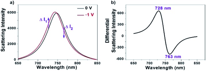
Owing to the sensitive dependence of LSPR on the changes in the surrounding dielectric environment and electron density, it allows us for studying different physical and chemical processes on the surface of the single nanoparticles by monitoring the scattering spectral changes.28–34 For instance, existing studies have shown that the LSPR band of AuNRs immobilized on the ITO substrate is subject to a blue-shift when applying a negative potential, which is due to the increase in the electron density of AuNRs under the electrochemical charging.35–38 We accordingly recorded the corresponding scattering spectrum of a single AuNR at different potentials as shown in Fig. 1a. The results are nicely consistent with literature reports.35,37,38 To date, maximal scattering wavelength (λmax) is the major optical parameter that reflects the electron density of AuNRs. Because it usually takes several seconds or even longer time to acquire a scattering spectrum, it is impossible to determine the λmax when applying an alternating potential as high as tens of kilohertz. In order to measure the optical response of single AuNRs under high-frequency modulation, monochromatic DFM is proposed in which the scattering intensity is recorded at a fixed single wavelength of incident light. The shift in the plasmonic band would increase or decrease the scattering intensity accordingly (Fig. 1a). For example, when the wavelength of the incident light is lower (higher) than the maximal scattering wavelength, a blue shift in the LSPR band would lead to an increased (decreased) scattering intensity. When the modulation voltage is sufficiently small, intensity change can be converted to the wavelength shift quantitatively. The benefit of such conversion is the significantly improved temporal resolution for studying the high frequency charging and discharging processes (see ESI Section 2.2†).
Fig. 1. (a) Full scattering spectra of a single AuNR at the voltages of 0 V (black) and –1 V (red), respectively. (b) Differential scattering spectrum of the two spectra shown in (a).
It is clear that optimization of the wavelength is critical to sensitively convert the spectral shift into the intensity change. Differential spectrum is a useful way for optimizing the wavelength of incident light. Fig. 1b shows a representative differential spectrum by subtracting the scattering spectrum (0 V) from the one after electron injection (–1 V). It is estimated that an incident light of 728 nm wavelength delivers the largest intensity change at the given spectral shift.
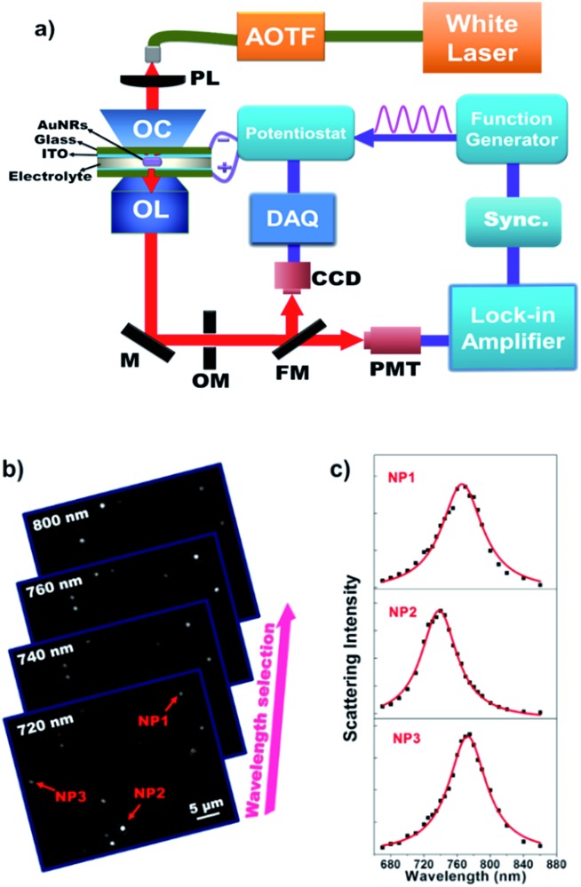
This hypothesis is subsequently validated with a home-built monochromatic DFM setup. Fig. 2a shows a schematic illustration of the optical setup for monitoring the electrochemical charging and discharging process of single AuNRs. Representative grayscaled images acquired using the present setup are displayed in Fig. 2b. The scattering spectrum of individual AuNRs is obtained by plotting the single nanoparticle scattering intensity as a function of illumination wavelength (Fig. 2c). We first prepared an electrochemical cell consisting of two opposite ITO glass slides. Here, the upper ITO electrode was applied to immobilize AuNRs. The LSPR of single AuNRs was illuminated using a supercontinuum white light laser source coupled with an acousto-optic tunable filter (AOTF) and an oil-immersed dark-field condenser. An intensified supercontinuum laser other than the halogen lamp was essential to provide sufficient photon flux in a short exposure time. A sinusoidal voltage from the function generator was applied to the electrochemical cell via the potentiostat. The scattered light of single AuNRs was collected using an objective and it was then detected by CCD or PMT. The EIS spectra of single AuNRs were obtained by determining the amplitude and phase of the corresponding optical intensity fluctuation at each frequency either by digital Fourier transform or by using an analog lock-in amplifier. The highest frame rate of this CCD camera is 953 frames per second, which allows for resolving the low-frequency EIS spectra (below 475 Hz) for multiple nanoparticles simultaneously. Usually, CCD measurements are used for initial screening of nanoparticles owing to its throughput. PMT coupled with an OptoMask was adopted to acquire the full EIS spectrum of one nanoparticle up to 30 kHz.
Fig. 2. (a) Schematic illustration of the optical setup for acquiring the EIS spectra of single AuNRs using DFM. AOTF = Acousto-Optic Tunable Filter, PL = Plano-convex Lens, OC = Oil Condenser, OL = Objective Lens, M = Mirror, OM = OptoMask, FM = Flip Mirror, CCD = Charged-Coupled Device, DAQ = Data Acquisition Board, PMT = Photon Multiplier Tube. A series of monochromatic images captured at different illumination wavelengths (b) are used to extract the scattering spectrum of single nanoparticles (c).
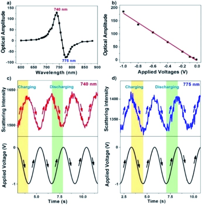
A series of different single wavelengths were examined to demonstrate that the scattering intensity fluctuations can be used to monitor the electrochemical charging and discharging of single AuNRs. The scattering intensity amplitudes of a single AuNR as a function of the incident light wavelength are shown in Fig. 3a. Positive amplitudes (Fig. 3c) mean that the decreased potential was accompanied by increasing intensity, which was expected because the negative potential charged the AuNRs with electrons and led to a blue shift in the LSPR band. Negative amplitudes (Fig. 3d), however, suggested that the decreased potential resulted in decreased intensity. Such a phase shift is because the incident light wavelength is larger than the maximal scattering wavelength. Therefore, the electrochemical charging and discharging process of single AuNRs can be tracked by using the single-wavelength-based scattering intensity change. Further examples (150 Hz for CCD and 10 kHz for PMT) are provided in the ESI (Fig. S3†). Fourier transform to the original scattering intensity curves demonstrated the periodic intensity fluctuation as a result of the potential modulation. Note that a negative potential is essential here to achieve the reversible non-faradaic charging and discharging processes. When applying a positive potential on the electrode, irreversible oxidation of AuNRs (Fig. S4†) and the adsorption of anions39,40 would compromise the data interpretation.
Fig. 3. (a) Scattering intensity amplitude of a single AuNR under the monochromatic illumination of different wavelengths. (b) Plot depicting the linear relationship between the applied voltages and scattering intensity amplitude. As a result of the modulating potential, original scattering intensity curves exhibit out-of-phase and in-phase responses under the illumination of (c) 740 and (d) 775 nm, respectively.
The sensitivity of the present setup to detect a small amount of charge quantity was investigated by applying a series of modulation voltages (Fig. 3b). As expected, it is found that the amplitude of scattering intensity modulation is linearly dependent on the applied potential. The present method allows for detecting voltage modulation as small as –10 mV, which is at least one order of magnitude more sensitive than previous reports that quantified the charging effect by directly measuring the spectral shift.35
EIS of single AuNRs
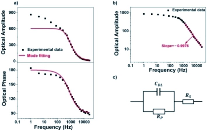
We next investigate the optical responses of surface-bound single AuNRs when charging them with a series of modulation frequencies. Semi-log and log–log (Bode) plots of the results are shown in Fig. 4a and b, respectively. When increasing the modulation from 1 Hz to 30 kHz, the amplitude of single nanoparticle scattering intensity fluctuation is found to decrease towards zero accordingly. Similar trends in the low frequency range (<400 Hz) were observed for the same individual AuNR when recording the EIS spectrum with CCD and PMT, respectively (Fig. S5 and S6†). This transition is accompanied by the decrease in the phase delay from 180° to 90°. These results were explained with a classical Randles model, as shown in Fig. 4c. The model consists of three circuit elements, including electrolyte resistance (RS), and polarization resistance (RP) in parallel with double layer capacitance (CDL). These parameters were resolved by fitting the conventional current-based impedance responses of the electrode surface (see ESI Fig. S7† for details). Because the AuNRs were located in the electrical double layer of the ITO electrode, the charging process was governed by the voltage drop across the double layer (UDL, see Fig. S8† for details):
 |
1 |
where Uapplied is the applied voltage, ω (=2πf) is the angular frequency, f is the voltage modulation frequency and j is the imaginary unit (j2 = –1).
Fig. 4. (a) Semi-log plots and (b) log–log (Bode) plot of scattering intensity amplitude and phase of a single AuNR as a function of frequency. The red line is calculated results from model fitting, and the black squares are experimental data. (c) Randles equivalent circuit of the electrochemical cell used in the present work.
The optical signal fluctuation of the single nanoparticle reflected the transferred charge quantity during the charging and discharging process (QNP), which was regulated by both double layer potential (UDL) and the surface capacitance of single nanoparticles (CNP):
| QNP = CNP × UDL | 2 |
These equations were used to fit the experimental results (red curves in Fig. 4a and b) to provide the relevant electrical parameters such as CDL, RS, and RP. The results are generally consistent with the fitted parameters from conventional EIS analysis (see ESI Table S1†). The slight difference was attributed to the spatial heterogeneity of the ITO electrode. The conventional EIS analysis reflected the behavior of the whole ITO electrode, and EIS of a single AuNR reflected the local behavior around it.
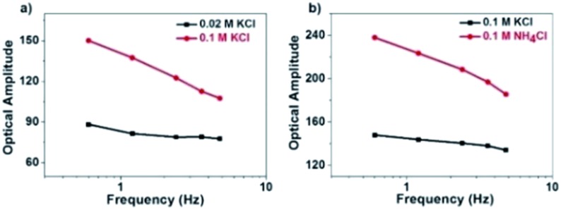
However, there is a clear inconsistency at frequencies lower than 100 Hz. While the theory predicts constant amplitude, larger amplitude is observed at lower frequency. We attribute the difference between the experimental and calculated data to the migration of positively charged ions towards the ITO electrode surface, whose accumulation increased the local refractive index and thus contributed additional scattering signals. Because the ionic migration takes place at a relatively slower time scale, its influence is expected to decrease at higher frequency. We excluded the possibility of the local heating effect because the illumination density (<3 × 10⁻³ mW μm–2) in the present setup should induce a temperature increase less than 1 mK according to a recent literature report (ESI Section 2.8†).41 The influence of the refractive index of the electrolyte solution at low frequency was confirmed by examining the influence of the type and concentration of electrolyte solutions on the responses (Fig. 5). More significant dependence of intensity fluctuation amplitude on the modulation frequency was observed under higher concentration of KCl solution (0.1 M vs. 0.02 M) as shown in Fig. 5a. Furthermore, for different types of electrolytes with identical concentration (KCl vs. NH4Cl) as shown in Fig. 5b, greater dependence was observed for NH4Cl. The refractive indices of 1 M KCl and NH4Cl solutions were determined to be 1.3426 and 1.3431, respectively. Because a negative potential was applied in this work, accumulation of cations in the electrolyte solution contributed most of the influences. The application of negative potential not only injected electrons into the nanoparticle, but also increased the concentration of cations in the outer Helmholtz plane as well as the migration layer. Both processes increased the scattering intensity but their time scales were different. Because the migration of counter-ions is a dynamic and relatively slower process, its contribution was greatly inhibited at higher frequency. As shown in Fig. 4a, the results show that the contribution of the refractive index of the electrolyte solution is more than 40% when applying a modulation frequency of 1 Hz. Its contribution is minimized at a frequency higher than 100 Hz. Note that the present setup is also suitable for studying the EIS of spherical gold nanoparticles at a shorter wavelength, although the signal-to-noise ratio would be compromised because the transverse plasmonic mode is less sensitive to the electron density (Fig. S9†).
Fig. 5. Influence of (a) electrolyte concentration and (b) electrolyte type on the amplitude of scattering intensity in the low-frequency range.
Capacitance of single AuNRs
EIS of single AuNRs not only allows for distinguishing the contributions from pure charging and migration of counter ions by frequency analysis, but also allows for determining the intrinsic surface capacitance of single AuNRs by applying a high frequency modulation (see ESI Section 2.10†). The surface capacitance of single AuNRs was determined to be 36.6 ± 11.8 μF cm–2 (N = 10, it is the number of AuNRs), which is in excellent agreement with the theoretical value.42,43 Significantly larger values were often obtained in a previous report that measured the scattering spectrum in direct current mode without high-frequency modulation.35 It was likely due to the incremental contributions in addition to pure electrochemical charging. As mentioned above, the effect of the refractive index of the electrolyte solution is obvious in the low frequency window, while single AuNRs show pure non-faradaic charging and discharging in the high frequency window. Therefore, the surface capacitance of single AuNRs was more accurately determined by using a high-frequency response.
Conclusions
In summary, we have presented a monochromatic dark-field microscopy technique to acquire the EIS spectra of single AuNRs by using the optical intensity fluctuation under potential modulation to quantify the charging states. Because the change in the refractive index of the surrounding medium due to counter ion migration is significantly slower compared with the intrinsic charging of AuNRs, EIS of single AuNRs allows for distinguishing these two contributions. While the refractive index effect plays important roles in the low-frequency range (<100 Hz), high-frequency response is dominated by the non-faradaic charging of AuNRs. As a result, the surface capacitance of single AuNRs can be more accurately determined by applying a high-frequency modulation of potential, which minimizes the refractive index contribution from the surrounding medium. This method is also suitable for studying other types of plasmonic nanomaterials. Furthermore, because the surface capacitance of the metal–electrolyte interface is known to be sensitive to the molecular recognition (binding) events, the present work is anticipated to pave a promising way towards single nanoparticle biosensing by measuring the surface capacitance under high-frequency modulation conditions.
Conflicts of interest
The authors declare no competing financial interests.
Supplementary Material
Acknowledgments
We acknowledge financial supports from the National Natural Science Foundation of China (Grants No. 21522503, 21705077, 21527807, and 21327902), and the Natural Science Foundation of Jiangsu Province (BK20150570 and BK20150013).
Footnotes
†Electronic supplementary information (ESI) available: Experimental details, Fig. S1–S11 and Table S1. See DOI: 10.1039/c8sc00983j
References
- Patolsky F., Lichtenstein A., Willner I. Angew. Chem., Int. Ed. 2000;39:940–943. [PubMed] [Google Scholar]
- Mantzila A. G., Maipa V., Prodromidis M. I. Anal. Chem. 2008;80:1169–1175. doi: 10.1021/ac071570l. [DOI] [PubMed] [Google Scholar]
- Cai D., Ren L., Zhao H., Xu C., Zhang L., Yu Y., Wang H., Lan Y., Roberts M. F., Chuang J. H., Naughton M. J., Ren Z., Chiles T. C. Nat. Nanotechnol. 2010;5:597–601. doi: 10.1038/nnano.2010.114. [DOI] [PMC free article] [PubMed] [Google Scholar]
- Prats-Alfonso E., Sisquella X., Zine N., Gabriel G., Guimera A., del Campo F. J., Villa R., Eisenberg A. H., Mrksich M., Errachid A., Aguilo J., Albericio F. Small. 2012;8:2106–2115. doi: 10.1002/smll.201102724. [DOI] [PMC free article] [PubMed] [Google Scholar]
- Luo X., Davis J. J. Chem. Soc. Rev. 2013;42:5944–5962. doi: 10.1039/c3cs60077g. [DOI] [PubMed] [Google Scholar]
- Huang B., Jia N., Chen L., Tan L., Yao S. Anal. Chem. 2014;86:6940–6947. doi: 10.1021/ac500753f. [DOI] [PubMed] [Google Scholar]
- Brabants G., Lieben S., Breynaert E., Reichel E. K., Taulelle F., Martens J. A., Jakoby B., Kirschhock C. E. Chem. Commun. 2016;52:5478–5481. doi: 10.1039/c6cc01106c. [DOI] [PubMed] [Google Scholar]
- Lacombre C. V., Trinh D., Bouvet G., Feaugas X., Mallarino S., Touzain S. Electrochim. Acta. 2017;234:7–15. [Google Scholar]
- Ogihara N., Itou Y., Sasaki T., Takeuchi Y. J. Phys. Chem. C. 2015;119:4612–4619. [Google Scholar]
- Lisdat F., Schaefer D. Anal. Bioanal. Chem. 2008;391:1555–1567. doi: 10.1007/s00216-008-1970-7. [DOI] [PubMed] [Google Scholar]
- Chang B. Y., Park S. M. Annu. Rev. Anal. Chem. 2010;3:207–229. doi: 10.1146/annurev.anchem.012809.102211. [DOI] [PubMed] [Google Scholar]
- Fernández-Sánchez C., McNeil C. J., Rawson K. TrAC, Trends Anal. Chem. 2005;24:37–48. [Google Scholar]
- Huang V. M., Wu S.-L., Orazem M. E., Pébère N., Tribollet B., Vivier V. Electrochim. Acta. 2011;56:8048–8057. [Google Scholar]
- Lillard R. S., Moran P. J., Isaacs H. S. J. Electrochem. Soc. 1992;139:1007–1012. [Google Scholar]
- Annergren I., Zou F., Thierry D. Electrochim. Acta. 1999;44:4383–4393. [Google Scholar]
- Hengstenberg A., Blochl A., Dietzel I. D., Schuhmann W. Angew. Chem., Int. Ed. 2001;40:905–908. [PubMed] [Google Scholar]
- Frateur I., Huang V. M., Orazem M. E., Tribollet B., Vivier V. J. Electrochem. Soc. 2007;154:C719–C727. [Google Scholar]
- Bandarenka A. S., Eckhard K., Maljusch A., Schuhmann W. Anal. Chem. 2013;85:2443–2448. doi: 10.1021/ac303490t. [DOI] [PubMed] [Google Scholar]
- Manesse M., Stambouli V., Boukherroub R., Szunerits S. Analyst. 2008;133:1097–1103. doi: 10.1039/b804825h. [DOI] [PubMed] [Google Scholar]
- Vandenryt T., Pohl A., van Grinsven B., Thoelen R., De Ceuninck W., Wagner P., Opitz J. Sensors. 2013;13:14650–14661. doi: 10.3390/s131114650. [DOI] [PMC free article] [PubMed] [Google Scholar]
- Patskovsky S., Latendresse V., Dallaire A. M., Dore-Mathieu L., Meunier M. Analyst. 2014;139:596–602. doi: 10.1039/c3an01685d. [DOI] [PubMed] [Google Scholar]
- Yuan L., Tao N., Wang W. Annu. Rev. Anal. Chem. 2017;10:183–200. doi: 10.1146/annurev-anchem-061516-045150. [DOI] [PubMed] [Google Scholar]
- Wang W., Foley K., Shan X., Wang S., Eaton S., Nagaraj V. J., Wiktor P., Patel U., Tao N. Nat. Chem. 2011;3:249–255. doi: 10.1038/nchem.961. [DOI] [PMC free article] [PubMed] [Google Scholar]
- Lu J., Li J. Angew. Chem. 2015;54:13576–13580. doi: 10.1002/anie.201505991. [DOI] [PubMed] [Google Scholar]
- Liu X. W., Yang Y., Wang W., Wang S., Gao M., Wu J., Tao N. Angew. Chem. 2017;56:8855–8859. doi: 10.1002/anie.201703033. [DOI] [PMC free article] [PubMed] [Google Scholar]
- Lu J., Wang W., Wang S., Shan X., Li J., Tao N. Anal. Chem. 2012;84:327–333. doi: 10.1021/ac202634h. [DOI] [PMC free article] [PubMed] [Google Scholar]
- MacGriff C., Wang S., Wiktor P., Wang W., Shan X., Tao N. Anal. Chem. 2013;85:6682–6687. doi: 10.1021/ac400475z. [DOI] [PubMed] [Google Scholar]
- Jing C., Gu Z., Ying Y.-L., Li D.-W., Zhang L., Long Y.-T. Anal. Chem. 2012;84:4284–4291. doi: 10.1021/ac203118g. [DOI] [PubMed] [Google Scholar]
- Jing C., Rawson F. J., Zhou H., Shi X., Li W.-H., Li D.-W., Long Y.-T. Anal. Chem. 2014;86:5513–5518. doi: 10.1021/ac500785u. [DOI] [PubMed] [Google Scholar]
- Jing C., Gu Z., Long Y.-T. Faraday Discuss. 2016;193:371–385. doi: 10.1039/c6fd00069j. [DOI] [PubMed] [Google Scholar]
- Jing C., Gu Z., Xie T., Long Y.-T. Chem. Sci. 2016;7:5347–5351. doi: 10.1039/c6sc00903d. [DOI] [PMC free article] [PubMed] [Google Scholar]
- Yin A., He Q., Lin Z., Luo L., Liu Y., Yang S., Wu H., Ding M., Huang Y., Duan X. Angew. Chem., Int. Ed. 2016;55:583–587. doi: 10.1002/anie.201508586. [DOI] [PubMed] [Google Scholar]
- Jing C., Reichert J. Curr. Opin. Electrochem. 2017;6:10–16. [Google Scholar]
- Lin Y., Ying Y.-L., Long Y.-T. Curr. Opin. Electrochem. 2018;7:172–178. [Google Scholar]
- Novo C., Funston A. M., Gooding A. K., Mulvaney P. J. Am. Chem. Soc. 2009;131:14664–14666. doi: 10.1021/ja905216h. [DOI] [PubMed] [Google Scholar]
- Byers C. P., Hoener B. S., Chang W.-S., Link S., Landes C. F. Nano Lett. 2016;16:2314–2321. doi: 10.1021/acs.nanolett.5b04990. [DOI] [PubMed] [Google Scholar]
- Collins S. S., Wei X., McKenzie T. G., Funston A. M., Mulvaney P. Nano Lett. 2016;16:6863–6869. doi: 10.1021/acs.nanolett.6b02696. [DOI] [PubMed] [Google Scholar]
- Hoener B. S., Zhang H., Heiderscheit T. S., Kirchner S. R., De Silva Indrasekara A. S., Baiyasi R., Cai Y., Nordlander P., Link S., Landes C. F., Chang W. S. J. Phys. Chem. Lett. 2017;8:2681–2688. doi: 10.1021/acs.jpclett.7b00945. [DOI] [PubMed] [Google Scholar]
- Dondapati S. K., Ludemann M., Mueller R., Schwieger S., Schwemer A., Haendel B., Kwiatkowski D., Djiango M., Runge E., Klar T. A. Nano Lett. 2012;12:1247–1252. doi: 10.1021/nl203673g. [DOI] [PubMed] [Google Scholar]
- Laurinavichyute V. K., Nizamov S., Mirsky V. M. ChemPhysChem. 2017;18:1552–1560. doi: 10.1002/cphc.201601288. [DOI] [PubMed] [Google Scholar]
- Chen Z., Shan X., Guan Y., Wang S., Zhu J.-J., Tao N. ACS Nano. 2015;9:11574–11581. doi: 10.1021/acsnano.5b05306. [DOI] [PubMed] [Google Scholar]
- Kolb D. M. Angew. Chem., Int. Ed. 2001;40:1162–1181. [PubMed] [Google Scholar]
- Foley K. J., Shan X., Tao N. J. Anal. Chem. 2008;80:5146–5151. doi: 10.1021/ac800361p. [DOI] [PubMed] [Google Scholar]
Associated Data
This section collects any data citations, data availability statements, or supplementary materials included in this article.


