

Abstract
Earth-abundant element-based inorganic–organic hybrid materials are attractive alternatives for electrocatalyzing energy conversion reactions. Such material structures do not only increase the surface area and stability of metal nanoparticles (NPs) but also modify the electrocatalytic performance. Here, we introduce, for the first time, multiwall carbon nanotubes (MWNTs) functionalized with nitrogen-rich emeraldine salt (ES) (denoted as ES-MWNT) as a promising catalyst support to boost the electrocatalytic activity of magnetic maghemite (γ-Fe2O3) NPs. The latter component has been synthesized by a simple and upscalable one-step pulsed laser ablation method on Ni core forming the core–shell Ni@γ-Fe2O3 NPs. The catalyst (Ni@γ-Fe2O3/ES-MWNT) is formed via self-assembly as strong interaction between ES-MWNT and Ni@γ-Fe2O3 results in NPs’ encapsulation in a thin C–N shell. We further show that Ni does not directly function as an active site in the electrocatalyst but it has a crucial role in synthesizing the maghemite shell. The strong interaction between the NPs and the support improves notably the NPs’ catalytic activity toward oxygen evolution reaction (OER) in terms of both onset potential and current density, ranking it among the most active catalysts reported so far. Furthermore, this material shows a superior durability to most of the current excellent OER electrocatalysts as the activity, and the structure, remains almost intact after 5000 OER stability cycles. On further characterization, the same trend has been observed for hydrogen evolution reaction, the other half-reaction of water splitting.
Keywords: catalyst support, maghemite (γ-Fe2O3), core−shell nanoparticles, carbon nanotubes, polymer functionalization, water splitting, self-assembly
1. Introduction
Hydrogen production by electrochemical water splitting is considered a promising route for renewable energy conversion and an enabler for hydrogen utilization as an energy carrier.1 In a water electrolysis device, the overall water-splitting reactions should be utilized in the same electrolyte. This is one of the challenges in electrocatalyst development because of the difficulty in finding earth-abundant catalysts enhancing the efficiency for both the oxygen evolution reaction (OER) and the hydrogen evolution reaction (HER) in the same electrolyte and under similar pH conditions. Because of this, development of an electrocatalyst with bifunctional activity for both water electrolysis half-reactions is specifically of high interest for large-scale device fabrication.
Oxides of first-row transition metals as earth-abundant and cost-effective materials have shown promising performance for water splitting1,2 Nonetheless, the catalytic activity and durability of these transition-metal-based electrocatalysts can be significantly improved by modifying the catalyst structure and the electronic properties of the catalyst surface.3,4 The latter can be tuned for subtle changes in the catalyst properties by changing the surface composition as well as by catalyst/support or shell–core interactions in the supported catalysts and core–shell nanoparticles (NPs), respectively.3−6 These changes can modify the binding energy of the reaction intermediates in order to improve the activity and stability of the electrocatalyst.4 One promising strategy to modify the structure and electronic properties of nanoparticulate electrocatalysts simultaneously is to increase the surface area, by selecting a suitable support, and making core–shell catalysts.
Carbon nanotubes (CNTs) have a high surface area, high thermal and chemical stability, excellent electrical conductivity, and special electronic properties, suggesting them as a suitable support for electrocatalysts.7 CNTs can strongly interact with nanoparticulate8 and even subnanometer9 catalysts for the fabrication of highly active and durable catalysts. Furthermore, CNTs are highly stable in the harsh conditions of the water splitting in alkaline media, and hence they are interesting catalyst supports for both the OER and the HER.10,11 CNTs can also be doped or functionalized with nitrogen-containing polymers12 or ligands.11 In these structures, N sites on the CNTs function as decoration sites for a stronger immobilization of NPs because of a higher catalyst/support interaction, leading to a significant charge transfer which can modify the catalytic activity of active sites.13
Recently, Au@metal-oxide6 core–shell NPs has also been introduced as highly active OER electrocatalysts in which the Au core is surrounded by an active transition-metal-oxide shell improving the catalytic activity of a surrounding active transition-metal shell. In general, core–shell structures provide unique, useful, and tailorable properties which advance these nanostructures as an important class of emerging nanomaterials.14 The interaction between the core and the shell is caused by their atomic vicinity, inducing charge transfer between the species, and this alters the electronic properties of the shell.15 Geometric effects, originating from a different three-dimensional structural construction, are another main impact of the core–shell nanostructures. The electronic and geometric effects,16 caused by the formation of core–shell structures, can modify the adsorption energies of the reactants and reaction intermediates for different catalytic sites located at the surface to improve the catalytic activity.
In this study, we show that magnetic γ-Fe2O3 is formed in the presence of the Ni NP core (Ni@γ-Fe2O3 core–shell NPs) with a facile one-pot sequential synthetic method using pulsed laser ablation in liquid (PLAL). PLAL technique has the ability to synthesize active electrocatalysts17,18 and has been selected as it is one of the most simple and tunable methods for the synthesis of magnetic NPs.19−21 Subsequently, the prepared Ni@γ-Fe2O3 NPs have been decorated on the nitrogen-rich emeraldine salt (ES)-functionalized multiwall carbon nanotubes (MWNTs), leading to a strong interaction between the magnetic maghemite (γ-Fe2O3) shell and ES. Consequently, nitrogen-rich ES wraps around the Ni@γ-Fe2O3 NPs, which modifies the catalyst surface and creates a highly durable catalyst. We demonstrate that the self-assembled C–N encapsulation layer protects the NPs from degradation and agglomeration with the neighboring NPs during the electrolysis. The Ni@γ-Fe2O3/ES-MWNT is reported here as a new class of highly active and stable material for water oxidation and reduction.
2. Results and Discussion
2.1. Material Synthesis and Morphology Characterization
Magnetic Ni@γ-Fe2O3 NPs have been synthesized via PLAL from alloy targets in acetone as explained in the synthesis process section (see Section 5). Ni@γ-Fe2O3 core–shell NPs with an average diameter of 12.3 nm [based on transmission electron microscopy (TEM) measurements, Figure S1] are obtained in this facile one-step synthesis process. The PLAL technique has been earlier demonstrated as a feasible technique for producing core–shell structures containing FeOx shells.20,22 It is noteworthy that the parameters for synthesizing NPs were optimized by taking into consideration the yield and uniformity of the sample. Furthermore, to attach the Ni@γ-Fe2O3 NPs to an electronically conducting support, ES-MWNTs have been synthesized as explained in our recent publication23 and summarized in the Experimental Section (Section 5). The Ni@γ-Fe2O3 NPs are decorated on the ES-MWNT simply by mixing them under bath sonication for 1 h (Scheme 1). In this step, the interaction between ES and the NPs induces the formation of another core–shell structure, comprising a polymer shell and an NP core, via self-assembly.
Scheme 1. Schematic Illustration for the Synthesis of the Ni@γ-Fe2O3 NPs and the Ni@γ-Fe2O3/ES-MWNT Hybrid Materials.

Two steps along the direction of the arrows (from the left to the right) illustrate the corresponding sequent synthesis stages.
The structures of the synthetized materials have been studied by high-resolution TEM (HRTEM). Figures 1a and S1 show the HRTEM observations of the Ni@γ-Fe2O3 NPs. Energy-dispersive spectroscopy (EDS) elemental mapping of Ni@γ-Fe2O3 is also obtained using an EDS coupled with the HRTEM to observe the elemental composition of the NPs. The overlay EDS mapping of the Ni@γ-Fe2O3 NPs (Figure 1b) exhibits the core–shell configuration of the NPs in which the core is Ni-rich, whereas the shell is mainly composed of Fe oxide. The Ni core and the iron oxide shell have been further studied by other characterization techniques (as discussed in the following sections) and identified as metallic Ni and maghemite (γ-Fe2O3), respectively. The HRTEM observation of the Ni@γ-Fe2O3 NPs after decoration on ES-MWNTs is shown in Figure 1c where the encapsulation of the NPs in a thin layer of ES is visible. The EDS/HRTEM mapping of the Ni@γ-Fe2O3 NPs has also been considered in Section 3, and those results clearly show the encapsulation of the NPs in the C–N layer from the ES.
Figure 1.
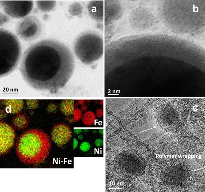
(a) HRTEM image of the Ni@γ-Fe2O3 core–shell NPs and (b) corresponding EDS elemental mapping overlay where Fe and Ni are shown by red and green colors, respectively. (c) HRTEM image of a crystalline γ-Fe2O3 shell. (d) HRTEM image of the Ni@γ-Fe2O3 NPs decorated on ES-functionalized MWNTs (Ni@γ-Fe2O3/ES-MWNT).
The NPs can be immobilized via self-assembly on the ES-MWNT support because of the strong electrostatic interaction between the Ni@γ-Fe2O3 NPs and the ES-MWNT. This interaction arises from the difference between the zeta potential of the Ni@γ-Fe2O3 NPs (∼−54) and the ES-MWNT (∼6) in acetone. ES, on the other hand, interacts with MWNTs, as shown in our recent investigation.23 Therefore, the role of ES is important for the formation of a stable material as it can strongly interact with both the MWNTs and the Ni@γ-Fe2O3 NPs.
The HRTEM images in Figure S2 show that the amount of dispersed Ni@γ-Fe2O3 NPs on MWNTs (without ES) is significantly decreased in the absence of ES. N sites in ES (see Figure S13 for the ES structure) can act as the anchoring sites for the metal NPs. In general, the presence of the N sites on the carbon support can immobilize the active metallic centers to form metal–nitrogen–carbon (M–N–C) species and facilitate the electrocatalytic process.24−26 Scanning electron microscopy (SEM) images shown in Figure S3 indicate that when the Ni@γ-Fe2O3 NPs interact only with ES (in the absence of MWNTs), a thick layer of the ES polymer covers the NPs (Ni@γ-Fe2O3/ES). The formation of a thick polymer layer around the NPs hinders mass transfer to the metal shell (γ-Fe2O3), resulting in low catalytic activity as explained in Section 2.2.
2.2. Considerations for Synthesizing Ni@γ-Fe2O3 Core–Shell NPs with PLAL
PLAL produces a plasma plume with high temperature and pressure, which contains highly ionized and excited species from both the target and the solvent. The liquid environment exposed to the plasma plume during generation of NPs has been reported to have a significant influence on the structure of the final products.20 This aspect has been exploited earlier to prepare different M@MOx NPs.27 Here, a NiFe target in acetone has been utilized for PLAL for the Ni@γ-Fe2O3 NP synthesis. As Fe has a higher negative adsorption enthalpy to acetone than Ni, formation of core–shell NPs with a Ni core and an FeOx shell is favored. Hence, plausibly the Ni core is formed in the beginning and subsequently the γ-Fe2O3 layer is shaped as a shell probably because of the higher nucleation rate of Ni compared to Fe.
The zeta potentials of the NiFe-based NPs synthesized in water and acetone are ∼−1.74 and ∼−54.3 mV, respectively. Here, only NPs synthesized in acetone showed a pronounced Ni@γ-Fe2O3 core–shell structure, indicating that the structure and morphology of the core–shell materials clearly differ depending on the solvents used during the laser ablation process. A similar solvent dependency has been previously observed for the formation of Cu@Cu2O NPs by laser-induced fragmentative decomposition of CuO, where the core–shell NPs have been formed in acetone because of the different high-temperature cooling periods between solvents.27
In addition to the solvent effect, we have found that the role of Ni is critical for the formation of the maghemite shell. To investigate the effect of Ni, the growth procedure of Ni@γ-Fe2O3/ES-MWNT has been repeated but the NiFe foil as the laser target was replaced with an Fe foil to synthesize FeOx NPs. The FeOx NPs had an average size of 12.5 nm (Figure S4), which is close to that measured for the Ni@γ-Fe2O3 NPs (12.3 nm).
2.3. X-ray Diffraction and Raman Characterization
The phase composition of the Ni@γ-Fe2O3 NP and the Ni@γ-Fe2O3/ES-MWNT samples was also investigated by X-ray diffraction (XRD) as shown in Figure S5a. The peak positions are well in agreement with the standard maghemite structure.28 However, one of the most powerful techniques for providing a clear assignment of the phase of the iron oxide or oxyhydroxide is Raman spectroscopy where all the different iron oxide phases reveal strong and distinct characteristic Raman active features.29 Raman spectroscopy can also detect crystalline NPs smaller than 4 nm and amorphous phases, which cannot be detected by XRD.30 Here, for the Ni@γ-Fe2O3/ES-MWNT, the Raman spectrum at the low-frequency region (Figures 2 and S6) displays the appearance of new features including the strongest peak in this region at ∼690 cm–1 and two weaker peaks at ∼572 and ∼461 cm–1. The strongest peak at ∼690 cm–1 is attributed to γ-Fe2O3 as only this phase of iron oxide shows its most pronounced Raman peak at this position,29 and for the small-sized maghemite this is almost the only observable Raman band.29 The weaker peaks in the range of 450–580 cm–1 can be assigned to the Ni core of the core–shell NPs.31 In contrast, Raman features at the low-frequency region for the FeOx NPs (Figure S6) agree well with the hematite structure.32,33 These results exhibit the crucial role of Ni for making maghemite containing the core–shell structure by PLAL.
Figure 2.
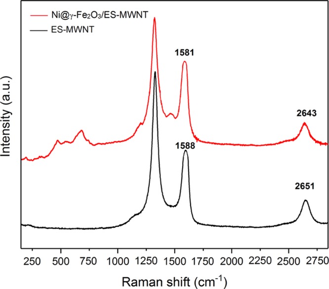
Raman spectra obtained from the ES-MWNT (black line) and Ni@γ-Fe2O3/ES-MWNT (red line) materials.
As shown in Figure 2, Raman spectra of the samples at the high-frequency region (Figure 2) display three major modes: the defect-induced D-mode at 1300–1360 cm–1, the graphitic mode (G mode) of CNTs at around 1600 cm–1, and the overtone of the D-band (G′ or 2D) at ∼2500–2800 cm–1.34 The so-called G′ band is observed in the Raman spectra of all kinds of sp2 carbon materials and is strongly sensitive to any perturbation to the π electronic structure.35 The G36 and especially the G′35 bands are shifted by the charge transfer between dopant additions on CNTs. These bands can be also used to assign p- and n-type doping in CNTs35 as they are blue-shifted and red-shifted upon doping, respectively. As shown in Figure 2, decorating the Ni@γ-Fe2O3 NPs on ES-MWNT causes red shifts of 7 and 8 cm–1 in the G and G′ bands, respectively, indicating that the Ni@γ-Fe2O3 NPs act as electron donor (n-type doping) dopants for the ES-MWNT support. After decorating the NPs, a new peak around 1480 cm–1 appears. Similarly, this peak has been observed for the functionalized CNTs with ES.37,38
2.4. X-ray Photoelectron Spectroscopy Characterizations
X-ray photoelectron spectroscopy (XPS) has been used to investigate the surface elemental composition of Ni@γ-Fe2O3/ES-MWNT at various stages of sample preparation and after exposing the hybrid catalyst to the OER (see Section 2 for the electrochemical measurements). The most relevant spectra are shown in Figures 3 and S7. The atomic concentrations are summarized in Table S1.
Figure 3.

Photoelectron spectra of (a) Fe 2p, (b) Ni 2p, and (c) N 1s for Ni@γ-Fe2O3/ES-MWNT (black line) and ES-MWNT (blue line). Deconvoluted components shown: amine (green line), protonated amine (purple line), protonated imine (yellow line), and N-oxide (light blue line).
Figure 3a shows the Fe 2p spectrum of Ni@γ-Fe2O3/ES-MWNT where four distinct peaks are observed. The complex combination of multiplet splitting and shake-up satellites makes the accurate interpretation of the iron spectrum difficult. The largest photoelectron peak maxima are found at binding energies of roughly 711.0 and 724.4 eV and are consistent with Fe 2p3/2 and Fe 2p1/2 peaks of γ-Fe2O3, respectively, but also with many other Fe(III) compounds.39,40 The additional smaller peaks detected at binding energies of roughly 707 and 720 eV can be ascribed to the metallic Fe 2p3/2 and Fe 2p1/2 peaks, respectively. Shake-up satellite peaks are associated with Fe(III) compounds.39 These can be useful for the identification of the exact Fe(III) species, but in our case the Fe 2p1/2 peak of metallic iron overlaps with the Fe(III) 2p3/2 satellite peak, making this difficult.
The presence of metallic Fe in the sample could indicate the existence of some NiFe alloy either near the core–shell interface of the NiFe core–shell NPs or as separate NiFe alloy NPs, although such alloy NPs were rarely detected in the HRTEM images.
Figure 3b shows the Ni 2p spectrum of the Ni@γ-Fe2O3/ES-MWNT sample. Again, a rather complex peak shape because of multiplet splitting and satellite peaks is found in the spectrum. The center binding energies for the most intense peak envelopes in the Ni 2p3/2 and Ni 2p1/2 regions are found at roughly 856.1 and 873.6 eV and the corresponding satellite peak regions at roughly 861.0 and 879.4 eV, respectively. These values together with the spectral shape point mostly toward nickel(III) oxyhydroxide, but because of the close similarly in the spectra, some nickel(II) hydroxide could be present as well.41 Smaller peaks at binding energies of roughly 853 and 870 eV can be ascribed to the Ni 2p3/2 and Ni 2p1/2 peaks of metallic Ni, respectively. The atomic concentrations of nickel and iron were found to be similar (see Table S1), but a larger amount of nickel is found in metallic form. Therefore, it is reasonable to assume that in addition to the possible NiFe alloys mentioned previously, also metallic nickel from the core of the core–shell NPs is observed. As the information depth of XPS is of the order of 5 nm, the entire NP will not be probed but photoelectrons from nickel close to the core–shell interface can still be observed. Their intensity will, however, be strongly attenuated by the surrounding shell.
The N 1s spectrum of Ni@γ-Fe2O3/ES-MWNT is shown in Figure 3c. The spectrum has been fitted by assuming the presence of five different nitrogen species: imine (=N−) at 398.5 eV, amine (−NH−) at 399.5 eV, protonated amine (−NH2+) at 401.1 eV, protonated imine (=NH+) at 402.2 eV, and one broader peak representing different nitrogen oxides (N-oxide) at 404–406 eV.42 For comparison, the nitrogen spectra were also measured for the ES-MWNT sample (without the NPs), shown in Figure 3c, and for the ES polymer, shown in Figure S7. The percentages of different nitrogen species derived from the peak fitting are shown in Table S2. Within the ES sample, no imine bonds were found as would be expected, indicating their full protonation. For ES-MWNT, slightly less protonated species, 38% in ES compared to 27% in ES-MWNT, are observed (see the structures depicted in Figure S13). After the incorporation of the Ni@γ-Fe2O3 NPs, the percentage of protonated species increases to 34% together with a clear increase in the amount of protonated imine bonds.
3. Electrochemical Measurements
3.1. Electrochemical Response of Ni@γ-Fe2O3/ES-MWNT by Cyclic Voltammetry
Cyclic voltammetry (CV) is an electrochemical technique, which can be used to study the kinetic of redox reactions of materials, and their insulating and conducting properties. For the ES form of polyaniline (PANI) coated on a conductive substrate, a pair of redox peaks in the CV have been observed, and they have been attributed to the protonation and deprotonation of the ES.43 Similarly, here, for the ES coated on highly conductive MWNTs, a pair of electrochemical redox peaks appear at an equilibrium potential [(Epa + Epc)/2, where Epa and Epc are anodic and cathodic peak potentials, respectively] of 0.67 V versus a reversible hydrogen electrode (RHE). For MWNTs functionalized with phenanthroline or bipyridine,11,44 a similar CV feature has been observed when the nitrogen functional groups strongly interact with the CNT support. For ES, which is not coated on the MWNT, the CV current is significantly lower than that of ES-MWNT (Figure 4), showing the essential role of MWNTs to facilitate charge transfer to/from the ES. After decoration of the Ni@γ-Fe2O3 NPs on ES-MWNT, the strong interaction between the NPs and ES hinders the conventional protonation and deprotonation in ES, causing almost a featureless CV for the Ni@γ-Fe2O/ES-MWNT sample (Figure 4). Diminishing the CV peaks of ES can be also due to the change in the ES structure after interacting with the γ-Fe2O3 NPs as described by the XPS analysis in Section 2.4 and Figure 3c. A similar change in the CV feature has been reported recently after metalation of bipyridine-functionalized MWNTs with Ni(II),11 attributed to the strong interaction of the metal sites with nitrogen moieties.
Figure 4.
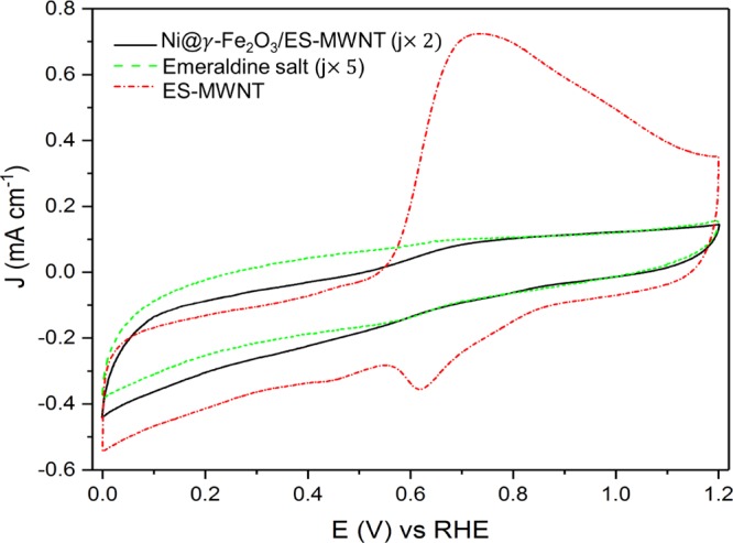
Cyclic voltammograms for Ni@γ-Fe2O3/ES-MWNT (black solid curve), ES (green dotted curve), and ES-MWNT (red dashed curve).
3.2. Oxygen Evolution Activity and Discussion
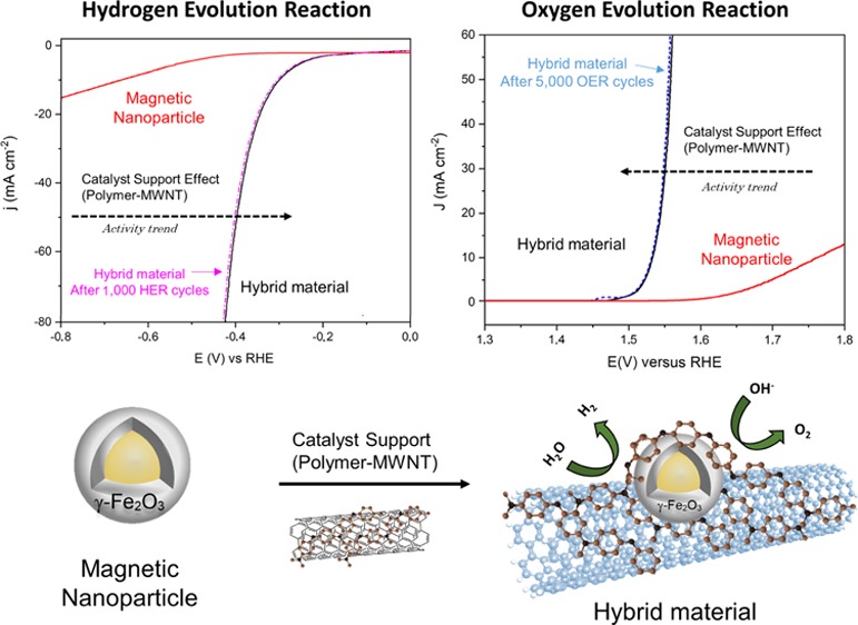
The electrocatalytic activity of all the samples for the OER was investigated in alkaline electrolytes (0.1 and 1 M NaOH) using a standard three-electrode system. All the measured materials were deposited on a glassy carbon (GC) electrode with a similar loading of ∼0.2 mg cm–2. Figure 5a shows the polarization curves of the Ni@γ-Fe2O3/ES-MWNT catalyst for the OER in comparison with pristine MWNT, ES-MWNT, Ni@γ-Fe2O3 NPs, and RuO2 electrodes in 0.1 M NaOH. The OER activity follows the trend Ni@γ-Fe2O3/ES-MWNT > RuO2 > Ni@γ-Fe2O3 > ES-MWNT ≥ MWNT. At low overpotentials (less than 450 mV), the pristine MWNT showed almost no catalytic activity for the OER, and the Ni@γ-Fe2O3 NPs result in a very low OER activity (Figure 5a). However, the OER activity of the Ni@γ-Fe2O3 NPs is significantly improved when they are immobilized on the ES-MWNT support, so that the OER overpotential for achieving a current density of 10 mA cm–2 in 0.1 M NaOH reduced from 540 mV for Ni@γ-Fe2O3 to 290 mV for Ni@γ-Fe2O3/ES-MWNT. This improvement in the activity can be attributed to an increase in the conductivity as well as a change in the surface composition of the NPs when the polymer is wrapped around the NPs as discussed in Section 1.1 and later in Section 3.
Figure 5.

(a) IR-corrected polarization curves obtained with Ni@γ-Fe2O3/ES-MWNT (black), MWNT (green), Ni@γ-Fe2O3 NPs (red), and RuO2 (blue) in 0.1 M NaOH and (b) corresponding Tafel plots derived from Figure (a). (c) OER polarization curves of Ni@γ-Fe2O3/ES-MWNT in 0.1 (black) and 1 M (red) NaOH solutions. (d) Detection of O2 generated on the Ni@γ-Fe2O3/ES-MWNT catalyst in a N2-saturated 0.1 M NaOH solution using RRDE measurements; the inset shows a scheme of the RRDE detection for the oxygen reduction reaction (ORR) on the Pt ring caused by the OER on the disc. The polarization curves were measured at a scan rate of 5 mV s–1 and a rotation speed of 1600 rpm.
Figure 5c demonstrates the activity of Ni@γ-Fe2O3/ES-MWNT in 0.1 and 1 M NaOH electrolytes (pHs of ∼13 and ∼14, respectively). The Ni@γ-Fe2O3/ES-MWNT catalyst only requires overpotentials of 300 and 330 mV in 0.1 M NaOH and 260 and 290 mV in 1 M NaOH to reach current densities of 10 and 50 mA cm–2 (denoted as ηOER,10 and ηOER,50), respectively.
The kinetics for oxygen evolution is assessed by Tafel plots (Figure 5b) derived from the OER polarization curves in Figure 5a. The Tafel slope can provide an insight into the reaction mechanism and the rate-determining step (RDS).45 The Tafel slope values of 45, 55, 95, 97, and 60 mV dec–1 are calculated for Ni@γ-Fe2O3/ES-MWNT, Ni@γ-Fe2O3 NPs, pristine MWNT, ES-MWNT, and RuO2, respectively (Figure 5a). The clearly different Tafel slope values for the unsupported Ni@γ-Fe2O3 NPs and Ni@γ-Fe2O3 NPs/ES-MWNT suggest a change in the OER mechanism and the RDS. The Tafel slope of the Ni@γ-Fe2O3/ES-MWNT material is close to the 40 mV dec–1 value, which has been reported for oxidized Ni, Co, and Fe in alkaline media.46,47 For the maghemite nanorods48 and NPs,49 a Tafel slope of 50–60 mV dec–1 has been reported in 0.1 M NaOH or KOH, which is close to the Tafel slope of Ni@γ-Fe2O3 NPs.
The Tafel slope is related to the reaction mechanism, and, hence, differences in the slopes can be attributed to a change in the RDS. Suggesting an OER mechanism solely on the basis of Tafel slope values is not feasible, anyway, as several different pathways have been introduced.50 However, in alkaline media, OH– adsorption on the electrocatalyst surface with charge transfer (S + OH– → S–OH + e–) has often been suggested as the RDS. Furthermore, assuming a single site mechanism, the following OER mechanism can be proposed on the basis of the literature
| 1 |
| 2 |
| 3 |
| 4 |
| 5 |
where S represents an active site on the catalyst. The Tafel slope of 45 mV dec–1 for NiFe/ES-MWNT is close to the value of 40 mV dec–1, which has been observed when eq 3 is the RDS.47,51
To detect the formation of oxygen on the Ni@γ-Fe2O3/ES-MWNT catalyst, rotating ring disc electrode (RRDE) measurements have also been carried out (Figure 5d). In such measurements, the oxygen evolved at the disc at different overpotentials is transported to the surrounding Pt ring electrode held at 0.4 V where the evolved oxygen is reduced to water. With this technique, the OER onset potential of Ni@γ-Fe2O3/ES-MWNT is measured to be ∼1.48 V versus RHE in 0.1 M NaOH. We have also estimated an approximate Faradaic efficiency (ε) >90% toward water oxidation catalyzed by Ni@γ-Fe2O3/ES-MWNT using these RRDE measurements52 with the OER current density less than 5 mA cm–2 (see the Supporting Information for the calculation). It is noteworthy that a small deviation from 100% efficiency does not necessarily mean the coexistence of other anodic processes than oxygen evolution as different factors can cause large errors in the measured value for ε.11 The ES-MWNT support exhibits almost no anodic current density at potentials <1.6 V, where the OER activity of Ni@γ-Fe2O3/ES-MWNT is reported. Thus, the measured anodic current density of the Ni@γ-Fe2O3/ES-MWNT catalyst in Figure 5a appears not to result from oxidative decomposition of the ES-MWNT support and is suggested to be ascribed only to the OER.
The Ni@γ-Fe2O3/ES-MWNT electrocatalyst exhibits a low onset overpotential and small overpotentials to obtain the high currents. The activity of Ni@γ-Fe2O3/ES-MWNT toward the alkaline OER is comparable to that of the most active OER electrocatalysts reported so far53−56 (see detailed comparisons in Table S3 in the Supporting Information). The performance of Ni@γ-Fe2O3/ES-MWNT toward the OER is also close to that observed for NiFe-layered double hydroxide nanoplates on mildly oxidized MWNTs [NiFe (LDH)/CNT] as the state-of-the-art electrocatalyst for the OER in alkaline media.53
As discussed in Section 2.2, the presence of Ni is critical for forming the maghemite shell. The latter can strongly interact with the ES-MWNT support and thus result in the formation of the active C–N encapsulation layer on the maghemite shell. For the FeOx/ES-MWNT sample, a significantly lower OER activity than for the Ni@γ-Fe2O3/ES-MWNT catalyst is observed (Figure S8). These results originate from the lack of magnetic maghemite NPs in the FeOx sample (Figure S6) and resulting less strong interaction between the nitrogen sites on ES-MWNT and the NPs. Consequently, the OER activity of FeOx/ES-MWNT is lower than that of Ni@γ-Fe2O3/ES-MWNT. As shown in Figure S8, both the unsupported FeOx and the Ni@γ-Fe2O3 NPs show relatively poor OER activity, whereas after supporting on ES-MWNT, the activity of the Ni@γ-Fe2O3 NPs is significantly improved compared to that of FeOx. This shows that these two NPs interact differently with the support. It is shown recently33 that maghemite NPs’ interaction with N-doped graphite carbon is stronger than that of hematite NPs. This can be one of the reasons for the higher activity of Ni@γ-Fe2O3/ES-MWNT compared to FeOx/ES-MWNT.
Among different iron oxide phases such as hematite,57,58 maghemite has shown a promising performance toward photoelectrochemical water oxidation.59,60 However, the electrocatalytic activity of hematite can be improved upon doping with other metals such as Co and Ni.61 For electrocatalytic water oxidation, maghemite nanorods anchored on nitrogen-doped CNTs have shown good OER activity,48 and that activity has been further improved in another work for γ-Fe2O3 NPs decorated on CNTs.62 Here, the Ni@γ-Fe2O3 NPs show a low OER activity, but it is significantly improved by interacting with the ES polymer supported on CNTs. Therefore, the role of the ES-MWNT is critical for obtaining a high OER catalytic activity, suggesting PANI-functionalized (ES form) CNT as a promising support for the metal NPs to prepare highly active and stable electrocatalysts. Hence, in comparison to the OER activity of other reported research studies on maghemite,48,62 which show significantly lower OER activity compared to Ni@γ-Fe2O3/ES-MWNT, it is concluded that solely γ-Fe2O3 does not result in the high OER activity. It is important to encapsulate Ni@γ-Fe2O3 NPs in the C–N shell because of the strong interaction between magnetic NPs and nitrogen sites in ES that result in the final high catalytic activity. Therefore, in the Ni@γ-Fe2O3/ES-MWNT catalyst, the Ni@γ-Fe2O3 NPs encapsulated in a C–N shell (from ES) are suggested as the most active sites in the sample.
For metal63,64/metal oxide26 NPs encapsulated in graphitized C–N shell(s), a significant charge transfer from the metal core to the C–N shell has been reported in the literature from density functional theory calculations. Such an electron transfer can modulate the electronic structure of the C–N shell, inducing a significant improvement in the electrocatalytic activity toward the HER,63 the OER,64 and other reactions such as ORRs.26 Similarly, here, the interaction between the C–N shell and Ni@γ-Fe2O3 leads to a significantly higher OER electrocatalytic activity of the Ni@γ-Fe2O3/ES-MWNT catalyst in comparison to the Ni@γ-Fe2O3 NPs. This interaction is further confirmed by the XPS results (as shown in Figure 3c), where a clear change is observed in the XPS spectrum of the ES-MWNT composite after decoration of the Ni@γ-Fe2O3 NPs.
For iron oxide catalysts, it has been recently shown that electronic structure and consequently the catalytic activity can be changed using different substrates.3,5,6 Similarly, here, the Ni core in the Ni@γ-Fe2O3 NPs can modify the electronic structure of the γ-Fe2O3 shell, and thus ultimately can indirectly affect the catalytic activity of the Ni@γ-Fe2O3/ES-MWNT catalyst.
We have also observed that the use of the ES-MWNT support for the γ-Fe2O3 NPs results in an active catalyst with a high electrochemically active surface area (ECSA) of ∼35 cm2, which is significantly larger than that calculated for unsupported metal oxide NPs65 and surface-oxidized MWNTs (6 cm2),66 and is similar to that of γ-Fe2O3/CNT.49 The ECSA of the catalyst is approximated from the electrochemical double-layer capacitance of the catalytic surface (see the calculation details in the Supporting Information) by applying CV measurements at different scan rates65,66 (Figure S9).
3.3. OER Stability Characterization
Stability under the harsh conditions of the OER is an important parameter to evaluate the performance of an electrocatalyst. In addition to high OER catalytic activity, the Ni@γ-Fe2O3/ES-MWNT catalyst also showed a high stability toward the OER, measured by 5000 potential cycles between 1.2 and 1.65 V at a scan rate of 50 mV s–1 (Figure 6a) and the chronoamperometric measurement at a constant potential of 1.52 V (where j is ∼10 mA cm–2) for 30 h (Figure 6b) in O2-saturated 0.1 M NaOH. As shown in Figure 6a, the OER polarization curve of Ni@γ-Fe2O3/ES-MWNT revealed no changes after 5000 potential cycles, whereas the RuO2 performance indicated a significant degradation after 1000 potential cycles. The significantly higher durability of Ni@γ-Fe2O3/ES-MWNT in comparison to RuO2 can be attributed to the presence of the ES-MWNT support, which strongly immobilizes the active NPs, protecting the NPs from degradation and agglomeration with neighboring NPs during the reaction.
Figure 6.

(a) OER polarization curves of the Ni@γ-Fe2O3/ES-MWNT before (black solid line) and after (red dot-dashed line) 5000 stability cycles between 1 and 1.65 V vs RHE at a scan rate of 50 mV s –1 in 0.1 M NaOH, compared to RuO2 before (green solid line) and after (blue dot-dashed line) 1000 stability cycles. (b) Time dependence of the current density in 0.1 M NaOH obtained at a static potential of ∼1.52 V for Ni@γ-Fe2O3/ES-MWNT and 1.6 V for RuO2.
After 5000 stability cycles, a small oxidation peak at ∼1.46 V emerges in the OER polarization curve of the Ni@γ-Fe2O3/ES-MWNT (Figure 6a). This peak is ascribed to reversible Ni oxidation reaction and may arise from oxidation of metallic Ni existing in rarely observed NiFe NPs in which Ni is not encapsulated in a maghemite shell. However, the appearance of the Ni oxidation peak does not significantly change the OER activity of the catalyst, indicating that these surface Ni species may not be the newly formed active sites at the catalyst surface.
To investigate the origin of the peak arisen after the OER stability tests, a similar OER stability test for the Ni@γ-Fe2O3 NPs (Figure S10) has been carried out. HRTEM images from the Ni@γ-Fe2O3 NPs after the OER stability test (Figure S11) show that the maghemite shell is stable in the NPs. Therefore, the Ni oxidation peak is suggested to mainly arise from oxidation of metallic Ni existing in the rarely observed NiFe alloy NPs in which Ni is not encapsulated in a maghemite shell. In addition, from the HRTEM images of the Ni@γ-Fe2O3 NPs, two type of NPs are observed (Figure S1). Both types of these NPs can serve as active sites. However, the vast majority in the sample are the Ni@γ-Fe2O3 NPs, whereas only a few NiFe alloy NPs are observed. The former NPs, as the dominant NPs, are suggested to be the NPs showing the main OER activity at the low overpotential region (0.25–0.32 V). The number of latter NPs is low (as such NPs are rarely seen in the HRTEM images) and hence not considered as the main contributor in the final OER electrocatalytic activity. As the OER stability cycles do not change the activity of the Ni@γ-Fe2O3/ES-MWNT sample at the low overpotential region (Figure 6), it is concluded that the appearance of the new oxidation peak at ∼1.46 V is not attributed to a change in the structure of the Ni@γ-Fe2O3NPs encapsulated in a C–N shell but rather to the NPs which are not encapsulated. Similarly, the OER polarization curves of the Ni@γ-Fe2O3 NPs (without the ES-MWNT support), before and after 100 stability cycles (Figure S10), show a new oxidation peak appearing before observing the OER current. However, in this case, the OER activity after 100 cycles has slightly decreased (Figure S10), as observed often for uncovered metal NPs.67
The chronoamperometric measurements were conducted based on the protocol for measuring the stability of heterogeneous electrocatalysts for the OER (half-cell measurements) through time-dependent measurements (chronoamperometry or chronopotentiometry).65 Through these measurements, the Ni@γ-Fe2O3/ES-MWNT catalyst exhibited a more stable performance than IrO2/C and the state-of-the-art NiFe LDH/CNT catalyst.53 Therefore, the Ni@γ-Fe2O3 NPs decorated on ES-MWNT can function as nonprecious, active, and durable electrocatalysts for catalyzing the OER.
3.4. Hydrogen Evolution Activity and Discussion
In addition to the superb OER performance discussed above, the HER activity of the Ni@γ-Fe2O3/ES-MWNT catalyst is also evaluated in N2-saturated 0.1 M NaOH to demonstrate the potential application of Ni@γ-Fe2O3/ES-MWNT as a bifunctional catalyst for full water splitting. Figure 7 shows the HER polarization curves on the Ni@γ-Fe2O3/ES-MWNT material compared with pristine MWNTs and the Ni@γ-Fe2O3 NPs. All the measured catalysts are deposited on a GC electrode with a similar loading of ∼0.2 mg cm–2. As shown in Figure 7, similar to the OER, the electrocatalytic enhancement for the hybrid material is observed in comparison to the Ni@γ-Fe2O3 NPs and pristine MWNT especially at high current densities. For the Ni@γ-Fe2O3/ES-MWNT hybrid material, an overpotential of 305 mV is required to achieve 10 mA m–2 in 0.1 M NaOH, which is comparable to that of transition/noble metal HER catalysts.68−70 Furthermore, the HER polarization curves on the Ni@γ-Fe2O3/ES-MWNT show no change after 1000 HER cycles, revealing the strong stability of this hybrid material.
Figure 7.
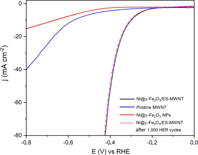
HER polarization curves of Ni@γ-Fe2O3/ES-MWNT (black line), pristine MWNT (blue line), Ni@γ-Fe2O3 NPs (red line), and Ni@γ-Fe2O3/ES-MWNT after 1000 HER cycles (pink dashed line). The polarization curves have been reported with iR compensation at a scan rate of 5 mV s–1 in 0.1 M NaOH.
4. Characterization of the Ni@γ-Fe2O3/ES-MWNT Catalyst after the Electrochemical Stability Experiments
Figure 8 exhibits the scanning TEM (STEM) and high-angle annular dark-field STEM (HAADF–STEM) images with the corresponding EDS mappings obtained from the Ni@γ-Fe2O3/ES-MWNT after 5000 and 1000 OER and HER stability cycles, respectively. In Figure 8a,b, the HRTEM and HAADF–STEM images show the core–shell structure of the Ni@γ-Fe2O3 NPs where the corresponding EDS spectra from the shell and the core show the Fe- and Ni-rich areas, respectively. Figure 8d shows the HRTEM images of two adjacent Ni@γ-Fe2O3 NPs decorated on the ES-MWNT support and Figure 8e–k indicates the corresponding elemental composition of the NPs by EDS mapping. Figure 8e,h exhibits clearly that N sites from the ES polymer have been wrapped around the Ni@γ-Fe2O3 NPs as already explained in Section 1.1. The comparison of Figure 8h (N mapping) with Figure 8i,j (Fe and Ni mappings, respectively) indicates that the N sites from the wrapped ES around the NPs have separated the two adjacent NPs, protecting the NPs from agglomerating during the electrochemical measurements and contributing the observed remarkable stability. It is notable that the nitrogen content is higher in the Ni@γ-Fe2O3 NP area (Figure 8e) where Fe–N–C can form and this could act as the active site.
Figure 8.

Structural and elemental analysis of Ni@γ-Fe2O3/ES-MWNT after electrochemical stability measurements. (a) STEM and corresponding (b) HAAD–STEM images of the Ni@γ-Fe2O3 core–shell NPs decorated on ES-MWNT. (c) EDS spectra obtained from the core and shell of the NP indicated in Figure (a). (d) STEM image of two adjacent NPs and corresponding EDS elemental mappings of (e) overlay of Fe, N, and C, (f) overlay of Fe, Ni, and O, (g) carbon, (h) nitrogen, (i) Fe, (j) Ni, and (k) oxygen.
Figure 8f,k shows that oxygen is mostly present in the shell and on the surface of the Ni@γ-Fe2O3 NPs, indicating that the Ni core of the NPs is not oxidized under the harsh oxidative OER conditions.
The XRD and Raman analyses (Figure S5) confirm the presence of γ-Fe2O3 in the Ni@γ-Fe2O3/ES-MWNT sample after the stability measurements. Furthermore, the Raman G and D bands of the Ni@γ-Fe2O3/ES-MWNT do not show a significant change after the durability test (Figure S5b), suggesting that the ES-MWNT support structure is stable during the long electrochemical stability tests.
On the basis of the XPS characterization of Ni@γ-Fe2O3/ES-MWNT after the stability measurements, the chemical states and amounts of iron and nickel are found to be similar to those before the reaction (see Figure S12a,b, and Table S1), indicating that the particles are rather stable. However, after the durability measurements, the ratio of oxidized Ni to metallic Ni seems to increase somewhat, which is in accordance with the observed evolution of the Ni oxidation peak in the OER polarization curve after 5000 OER cycles (Figure 6a). This slight increase in the amount of Ni oxide species probably arises from the oxidation of diffused Ni to the surface of the Ni@γ-Fe2O3 NPs during electrochemical measurements or from some metallic NiFe NPs, which have not been completely encapsulated in a γ-Fe2O3 shell.
Figure S12c shows the N 1s spectrum of Ni@γ-Fe2O3/ES-MWNT after the electrochemical measurements. The protonated imine peak at 402.2 eV almost vanishes and a previously undetected imine peak at 398.5 eV is observed. After the electrochemical measurements, the percentage of protonated imine bonds decreases to 3% from 17% (Table S2), suggesting that the protonated imine bonds of ES are mostly deprotonated during the measurements. In addition, after the stability measurements, the amounts of amine and imine bonds have decreased and increased, respectively, which could indicate that some amine bonds have been transformed to imine bonds. In the alkaline media, in which the electrochemical measurements have been carried out, ES can react with OH– to form the emeraldine salt base form of PANI (Figure S13 shows different forms of PANI). This can be reduced further to the leucoemeraldine form. This is consistent with the XPS measurements that indicate at least a partial deprotonation of the ES backbone toward its base form. The emeraldine ⇔ leucoemeraldine reversible transition has been shown to be involved in passivation layer of metals coated by PANI.71,72
5. Experimental Section
5.1. Chemicals and Materials
PANI ES (molecular weight ≈ 15 000) was purchased from Sigma-Aldrich and was kept in a glove box under inert atmosphere. MWNTs were purchased from Nanocyl. Nafion (10%) and IrO2 were both purchased from Sigma-Aldrich. Hydrochloric acid (HCl) was obtained from Merck (Whitehouse Station, NJ). All chemicals were of analytical-reagent grade and all the chemicals were used as received without further purification.
5.2. Synthesis Process
5.2.1. Step I: Synthesis Process of Ni@γ-Fe2O3 NPs
The preparation of Ni@γ-Fe2O3 NPs followed previous reports.1 Briefly, NiFe NPs were synthesized by ultrashort-PLALs as a facile technique for synthesis of NPs described in detail elsewhere.1 For this process, an Nd:YAG laser (Ekspla, Atlantic) with a fundamental wavelength of 1064 nm, a pulse duration of 10 ps, and a repetition rate of 100 kHz was used. A scanner (SCANcube 10, Scanlab) moved the laser beam in a spiral pattern and it was focused on the target with an f-theta lens (focal lens of 100 mm). The actual pulse energy applied, after the scanner and all optics, was 95 μJ. For synthesizing the NPs, a NiFe (50–50%, Sekels) or Fe (for synthesis of Fe NPs) foil (Aldrich Chemicals) was placed in a self-constructed stirred 100 mL aluminum batch chamber. The chamber was filled with acetone (analytical reagent grade, Fisher Chemical) and the ablation was carried out for 20 min. The collected colloid was used for further processing and analysis. To adjust the concentration, the solvent was evaporated at ambient temperature and pressure.
5.2.2. Step II: Synthesis Procedure for Functionalization of MWNTs with ES
At first, MWNTs (40.0 mg, purchased from Nanocyle) were dispersed in 100 mL of aqueous HCl solution (0.0025 M, pH 2.6) and sonicated with an ultrasonic bath (40 kHz, 40 W power) for 30 min, forming a stable black aqueous colloid (0.4 mg/mL). Separately, ES (100 mg, purchased from Sigma-Aldrich) was dispersed in 100 mL of 0.0025 M HCl (pH 2.6) and sonicated for 30 min as well, forming a stable deep green colloid (1.0 mg/mL). Because the size of commercially prepared ES is on the nanoscale, a stable colloid can be formed through electrostatic repulsion of the backbone of the positively charged ES dispersion in an acidic aqueous solution. Kaner et al.2 reported that the stability of the ES colloid is strongly pH-dependent and the pH value of 2.6 was the most optimal value. In our experiments, to eliminate the influence of differing pH values, the pH values of the MWNTs and ES aqueous colloids were both 2.6. Then, a 30 mL aliquot of the MWNT colloid was mixed with 30 mL aliquots of the ES colloid, and the mixture was sonicated for 2 h. After centrifugation (10 min, 4000 rpm) and drying in a vacuum oven, the final product (ES-MWNT) was prepared.
5.2.3. Step III: Procedure for Decorating Ni@γ-Fe2O3 NPs on ES-MWNT
As-prepared Ni@γ-Fe2O3 NPs (10 mL) in acetone (0.4 g/L) was mixed with 120 mg of ES-MWNT, stirred for 30 min, and sonicated for 15 min to obtain a homogenous dispersed ink. Then, the final ink was used for the electrochemical measurements.
5.3. Electrochemical Measurements
The measurements were carried out with an Autolab potentiostat in a standard three-electrode system using a GC disc, a Pt wire, and a calomel electrode as a working, counter, and reference electrode, respectively. All measured potentials were changed to the RHE scale using the following equation: E(RHE) = E(SCE) + 0.242 V + 0.059 × pH. The catalyst inks were deposited on the GC electrodes (0.19 cm2) with the same loading of ∼0.2 mg cm–2. Subsequently, 25 μL of a 5 wt % Nafion dispersion was diluted with 1 mL of ethanol, and 5 μL of this solution was then added on top of the catalyst layers as a binder. Polarization curves were obtained using linear sweep voltammetry with a scan rate of 5 mV s–1 in 0.1 and 1 M NaOH electrolyte solutions. After the durability measurements, the electrolyte was changed to a fresh one before recording the OER activity. The uncompensated ohmic electrolyte resistance (Ru) was calculated by extrapolating Ru to the minimum total impedance in a non-Faradaic region, measured by impedance spectroscopy between 10 Hz and 100 kHz. The values of Ru ≈ 22 Ω and Ru ≈ 9 Ω were recorded in 0.1 and 1 M NaOH solutions, respectively.
5.4. Physical Characterization
5.4.1. Zeta Potential Measurements for NPs
Zeta potential measurements were carried out with a Malvern Zetasizer Nano ZS using a solvent-resistant dip cell.
5.4.2. X-ray Photoelectron Spectroscopy
XPS was performed using a Kratos Axis Ultra spectrometer with monochromated Al Kα radiation, using a pass energy of 40 eV and an X-ray power of 225 W. Samples were measured as powders dispersed on a gold foil except the sample characterized after the OER measurements, which was measured directly on the GC electrode. The analysis area was roughly 700 μm × 300 μm for all the samples. The binding energy scale was referenced to the graphitic C 1s peak at 284.4 eV. The peak fitting of the nitrogen 1s region was done using Gaussian–Lorentzian peaks (70% Gaussian) with positions fixed to within ±0.2 eV of given values and the full width at half-maximum (fwhm) restricted to be equal. The N-oxide peak position was restricted to between 404 and 408 eV with the fwhm restricted to below 4 eV.
5.4.3. Raman Studies
The Raman spectra were carried out using a JY LabRam 300 with 1.96 eV (633 nm) laser excitation.
5.4.4. TEM Analysis
For TEM characterization, the samples were dispersed in ethanol (∼0.01 mg/mL) and then 10 μL of the solution was drop cast on a carbon-coated TEM grid (Cu grid) and dried in ambient air to form an ultrathin film of the materials on the grid. All TEM images were obtained using a JEOL-2200FS, double Cs-corrected HRTEM at an acceleration voltage of 200 kV.
6. Conclusions
In summary, a facile and upscalable synthesis method has been developed to produce magnetic maghemite NPs on the Ni substrate by laser ablation technique in acetone. We also reveal that Ni has a crucial role in producing the γ-Fe2O3 shell. Moreover, for the first time, it is shown that MWNTs functionalized with ES, a conductive polymer with positively charged nitrogen moieties, can strongly immobilize the magnetic Ni@γ-Fe2O3 NPs through electrostatic interaction via self-assembly. Characterization of the Ni@γ-Fe2O3/ES-MWNT sample before and after electrochemical measurements reveals that the Ni@γ-Fe2O3 NPs containing a magnetic maghemite shell have been captured in the ES polymer supported on MWNT, attributed mainly to the strong electrostatic interaction of the NPs with the ES. The Ni@γ-Fe2O3/ES-MWNT exhibits a high catalytic activity toward full alkaline water splitting. Furthermore, this catalyst shows a remarkable stability during dynamic electrochemical cycles. Such a performance originates from the unique structure of both the Ni@γ-Fe2O3 NPs and the ES-MWNT support. This work opens new doors to the synthesis of a new class of highly active and durable nanocatalysts for energy applications.
Acknowledgments
This work is supported by the Academy of Finland (the DEMEC 13286266 and CloseLoop 13303452 projects) and by the German Federal Ministry of Education and Research (BMBF) within the project NEMEZU (03SF0497C) and the ZIM Aif Projekt under grant no. KF2210319LP4. BG acknowledges funding from the DFG within the grant GO 2566/2-1. This work made use of the Aalto University Nanomicroscopy Center (Aalto-NMC) and RaMI Raw material Infrastructure premises. The authors would like to thank Prof. Stephan Barcikowski and Prof. Kari Laasonen for fruitful discussions.
Supporting Information Available
The Supporting Information is available free of charge on the ACS Publications website at DOI: 10.1021/acsami.8b08830.
Synthesis procedures, electrochemical measurements, XPS, Raman, XRD, SEM, and TEM images, and related references (PDF)
The authors declare no competing financial interest.
Supplementary Material
References
- Roger I.; Shipman M. A.; Symes M. D. Earth-Abundant Catalysts for Electrochemical and Photoelectrochemical Water Splitting. Nat. Rev. Chem. 2017, 1, 0003. 10.1038/s41570-016-0003. [DOI] [Google Scholar]
- Yang Y.; Niu S.; Han D.; Liu T.; Wang G.; Li Y. Progress in Developing Metal Oxide Nanomaterials for Photoelectrochemical Water Splitting. Adv. Energy Mater. 2017, 7, 1700555. 10.1002/aenm.201700555. [DOI] [Google Scholar]
- Chakthranont P.; Kibsgaard J.; Gallo A.; Park J.; Mitani M.; Sokaras D.; Kroll T.; Sinclair R.; Mogensen M. B.; Jaramillo T. F. Effects of Gold Substrates on the Intrinsic and Extrinsic Activity of High-Loading Nickel-Based Oxyhydroxide Oxygen Evolution Catalysts. ACS Catal. 2017, 7, 5399–5409. 10.1021/acscatal.7b01070. [DOI] [Google Scholar]
- Bandarenka A. S.; Koper M. T. M. Structural and Electronic Effects in Heterogeneous Electrocatalysis: Toward a Rational Design of Electrocatalysts. J. Catal. 2013, 308, 11–24. 10.1016/j.jcat.2013.05.006. [DOI] [Google Scholar]
- Ng J. W. D.; García-Melchor M.; Bajdich M.; Chakthranont P.; Kirk C.; Vojvodic A.; Jaramillo T. F. Gold-Supported Cerium-Doped NiOx Catalysts for Water Oxidation. Nat. Energy 2016, 1, 16053. 10.1038/nenergy.2016.53. [DOI] [Google Scholar]
- Strickler A. L.; Escudero-Escribano M.; Jaramillo T. F. Core-Shell Au@Metal-Oxide Nanoparticle Electrocatalysts for Enhanced Oxygen Evolution. Nano Lett. 2017, 17, 6040–6046. 10.1021/acs.nanolett.7b02357. [DOI] [PubMed] [Google Scholar]
- Zhu J.; Holmen A.; Chen D. Carbon Nanomaterials in Catalysis: Proton Affinity, Chemical and Electronic Properties, and Their Catalytic Consequences. ChemCatChem 2013, 5, 378–401. 10.1002/cctc.201200471. [DOI] [Google Scholar]
- Li Y.; Gong M.; Liang Y.; Feng J.; Kim J.-E.; Wang H.; Hong G.; Zhang B.; Dai H. Advanced Zinc-Air Batteries Based on High-Performance Hybrid Electrocatalysts. Nat. Commun. 2013, 4, 1805. 10.1038/ncomms2812. [DOI] [PubMed] [Google Scholar]
- Tavakkoli M.; Holmberg N.; Kronberg R.; Jiang H.; Sainio J.; Kauppinen E. I.; Kallio T.; Laasonen K. Electrochemical Activation of Single-Walled Carbon Nanotubes with Pseudo-Atomic-Scale Platinum for the Hydrogen Evolution Reaction. ACS Catal. 2017, 7, 3121–3130. 10.1021/acscatal.7b00199. [DOI] [Google Scholar]
- Tavakkoli M.; Kallio T.; Reynaud O.; Nasibulin A. G.; Johans C.; Sainio J.; Jiang H.; Kauppinen E. I.; Laasonen K. Single-Shell Carbon-Encapsulated Iron Nanoparticles: Synthesis and High Electrocatalytic Activity for Hydrogen Evolution Reaction**. Angew. Chem., Int. Ed. 2015, 54, 4535–4538. 10.1002/anie.201411450. [DOI] [PubMed] [Google Scholar]
- Tavakkoli M.; Nosek M.; Sainio J.; Davodi F.; Kallio T.; Joensuu P. M.; Laasonen K. Functionalized Carbon Nanotubes with Ni(II) Bipyridine Complexes as Efficient Catalysts for the Alkaline Oxygen Evolution Reaction. ACS Catal. 2017, 7, 8033–8041. 10.1021/acscatal.7b02878. [DOI] [Google Scholar]
- He D.; Zeng C.; Xu C.; Cheng N.; Li H.; Mu S.; Pan M. Polyaniline-Functionalized Carbon Nanotube Supported Platinum Catalysts. Langmuir 2011, 27, 5582–5588. 10.1021/la2003589. [DOI] [PubMed] [Google Scholar]
- Mabena L. F.; Sinha Ray S.; Mhlanga S. D.; Coville N. J. Nitrogen-Doped Carbon Nanotubes as a Metal Catalyst Support. Appl. Nanosci. 2011, 1, 67–77. 10.1007/s13204-011-0013-4. [DOI] [Google Scholar]
- Gawande M. B.; Goswami A.; Asefa T.; Guo H.; Biradar A. V.; Peng D.-L.; Zboril R.; Varma R. S. Core–shell nanoparticles: synthesis and applications in catalysis and electrocatalysis. Chem. Soc. Rev. 2015, 44, 7540–7590. 10.1039/c5cs00343a. [DOI] [PubMed] [Google Scholar]
- Strasser P.; Koh S.; Anniyev T.; Greeley J.; More K.; Yu C.; Liu Z.; Kaya S.; Nordlund D.; Ogasawara H.; et al. Lattice-strain control of the activity in dealloyed core-shell fuel cell catalysts. Nat. Chem. 2010, 2, 454–460. 10.1038/nchem.623. [DOI] [PubMed] [Google Scholar]
- Kitchin J. R.; Nørskov J. K.; Barteau M. A.; Chen J. G. Modification of the Surface Electronic and Chemical Properties of Pt(111) by Subsurface 3d Transition Metals. J. Chem. Phys. 2004, 120, 10240–10246. 10.1063/1.1737365. [DOI] [PubMed] [Google Scholar]
- Blakemore J. D.; Gray H. B.; Winkler J. R.; Müller A. M. Co3O4 Nanoparticle Water-Oxidation Catalysts Made by Pulsed-Laser Ablation in Liquids. ACS Catal. 2013, 3, 2497–2500. 10.1021/cs400639b. [DOI] [Google Scholar]
- Marzun G.; Levish A.; Mackert V.; Kallio T.; Barcikowski S.; Wagener P. Laser Synthesis, Structure and Chemical Properties of Colloidal Nickel-Molybdenum Nanoparticles for the Substitution of Noble Metals in Heterogeneous Catalysis. J. Colloid Interface Sci. 2017, 489, 57–67. 10.1016/j.jcis.2016.09.014. [DOI] [PubMed] [Google Scholar]
- Wagener P.; Jakobi J.; Rehbock C.; Chakravadhanula V. S. K.; Thede C.; Wiedwald U.; Bartsch M.; Kienle L.; Barcikowski S. Solvent-Surface Interactions Control the Phase Structure in Laser-Generated Iron-Gold Core-Shell Nanoparticles. Sci. Rep. 2016, 6, 23352. 10.1038/srep23352. [DOI] [PMC free article] [PubMed] [Google Scholar]
- Amendola V.; Riello P.; Meneghetti M. Magnetic Nanoparticles of Iron Carbide, Iron Oxide, Iron@iron Oxide, and Metal Iron Synthesized by Laser Ablation in Organic Solvents. J. Phys. Chem. C 2011, 115, 5140–5146. 10.1021/jp109371m. [DOI] [Google Scholar]
- Simao T.; Chevrier D. M.; Jakobi J.; Korinek A.; Goupil G.; Lau M.; Garbarino S.; Zhang P.; Barcikowski S.; Fortin M.-A.; et al. Gold-Manganese Oxide Core-Shell Nanoparticles Produced by Pulsed Laser Ablation in Water. J. Phys. Chem. C 2016, 120, 22635–22645. 10.1021/acs.jpcc.6b05838. [DOI] [Google Scholar]
- Kanitz A.; Hoppius J. S.; del Mar Sanz M.; Maicas M.; Ostendorf A.; Gurevich E. L. Synthesis of Magnetic Nanoparticles by Ultrashort Pulsed Laser Ablation of Iron in Different Liquids. ChemPhysChem 2017, 18, 1155–1164. 10.1002/cphc.201601252. [DOI] [PubMed] [Google Scholar]
- Davodi F.; Tavakkoli M.; Lahtinen J.; Kallio T. Straightforward Synthesis of Nitrogen-Doped Carbon Nanotubes as Highly Active Bifunctional Electrocatalysts for Full Water Splitting. J. Catal. 2017, 353, 19–27. 10.1016/j.jcat.2017.07.001. [DOI] [Google Scholar]
- Zhu Y. P.; Guo C.; Zheng Y.; Qiao S.-Z. Surface and Interface Engineering of Noble-Metal-Free Electrocatalysts for Efficient Energy Conversion Processes. Acc. Chem. Res. 2017, 50, 915–923. 10.1021/acs.accounts.6b00635. [DOI] [PubMed] [Google Scholar]
- Ren J.; Antonietti M.; Fellinger T.-P. Efficient Water Splitting Using a Simple Ni/N/C Paper Electrocatalyst. Adv. Energy Mater. 2015, 5, 1401660. 10.1002/aenm.201401660. [DOI] [Google Scholar]
- Wu Z.-S.; Yang S.; Sun Y.; Parvez K.; Feng X.; Müllen K. 3D Nitrogen-Doped Graphene Aerogel-Supported Fe3O4 Nanoparticles as Efficient Electrocatalysts for the Oxygen Reduction Reaction. J. Am. Chem. Soc. 2012, 134, 9082–9085. 10.1021/ja3030565. [DOI] [PubMed] [Google Scholar]
- Zhang D.; Gökce B.; Barcikowski S. Laser Synthesis and Processing of Colloids: Fundamentals and Applications. Chem. Rev. 2017, 117, 3990–4103. 10.1021/acs.chemrev.6b00468. [DOI] [PubMed] [Google Scholar]
- Rajput S.; Singh L. P.; Pittman C. U.; Mohan D. Lead (Pb 2+ ) and copper (Cu 2+ ) remediation from water using superparamagnetic maghemite (γ-Fe 2 O 3 ) nanoparticles synthesized by Flame Spray Pyrolysis (FSP). J. Colloid Interface Sci. 2017, 492, 176–190. 10.1016/j.jcis.2016.11.095. [DOI] [PubMed] [Google Scholar]
- Jubb A. M.; Allen H. C. Vibrational Spectroscopic Characterization of Hematite, Maghemite, and Magnetite Thin Films Produced by Vapor Deposition. ACS Appl. Mater. Interfaces 2010, 2, 2804–2812. 10.1021/am1004943. [DOI] [Google Scholar]
- Landon J.; Demeter E.; İnoğlu N.; Keturakis C.; Wachs I. E.; Vasić R.; Frenkel A. I.; Kitchin J. R. Spectroscopic Characterization of Mixed Fe-Ni Oxide Electrocatalysts for the Oxygen Evolution Reaction in Alkaline Electrolytes. ACS Catal. 2012, 2, 1793–1801. 10.1021/cs3002644. [DOI] [Google Scholar]
- Louie M. W.; Bell A. T. An Investigation of Thin-Film Ni-Fe Oxide Catalysts for the Electrochemical Evolution of Oxygen. J. Am. Chem. Soc. 2013, 135, 12329–12337. 10.1021/ja405351s. [DOI] [PubMed] [Google Scholar]
- de Faria D. L. A.; Lopes F. N. Heated Goethite and Natural Hematite: Can Raman Spectroscopy Be Used to Differentiate Them?. Vib. Spectrosc. 2007, 45, 117–121. 10.1016/j.vibspec.2007.07.003. [DOI] [Google Scholar]
- Sharifi T.; Gracia-Espino E.; Reza Barzegar H.; Jia X.; Nitze F.; Hu G.; Nordblad P.; Tai C.-W.; Wågberg T. Formation of Nitrogen-Doped Graphene Nanoscrolls by Adsorption of Magnetic Gamma-Fe2O3 Nanoparticles. Nat. Commun. 2013, 4, 2319. 10.1038/ncomms3319. [DOI] [PubMed] [Google Scholar]
- Rebelo S. L. H.; Guedes A.; Szefczyk M. E.; Pereira A. M.; Araújo J. P.; Freire C. Progress in the Raman Spectra Analysis of Covalently Functionalized Multiwalled Carbon Nanotubes: Unraveling Disorder in Graphitic Materials. Phys. Chem. Chem. Phys. 2016, 18, 12784–12796. 10.1039/c5cp06519d. [DOI] [PubMed] [Google Scholar]
- Maciel I. O.; Anderson N.; Pimenta M. A.; Hartschuh A.; Qian H.; Terrones M.; Terrones H.; Campos-delgado J.; Rao A. M.; Novotny L.; et al. Electron and Phonon Renormalization near Charged Defects in Carbon Nanotubes. Nat. Mater. 2008, 11, 878–883. 10.1038/nmat2296. [DOI] [PubMed] [Google Scholar]
- Rao A. M.; Eklund P. C.; Bandow S.; Thess A.; Smalley R. E. Evidence for Charge Transfer in Doped Carbon Nanotube Bundles from Raman Scattering. Nature 1997, 388, 257–259. 10.1038/40827. [DOI] [Google Scholar]
- Wei J.; Zhang C.; Du Z.; Li H.; Zou W. Modification of Carbon Nanotubes with 4-Mercaptobenzoic Acid-Doped Polyaniline for Quantum Dot Sensitized Solar Cells. J. Mater. Chem. C 2014, 2, 4177. 10.1039/c4tc00021h. [DOI] [Google Scholar]
- Lefrant S.; Baibarac M.; Baltog I.; Mevellec J. Y.; Godon C.; Chauvet O. Functionalization of Single-Walled Carbon Nanotubes with Conducting Polymers Evidenced by Raman and FTIR Spectroscopy. Diamond and Related Materials 2005, 14, 867–872. 10.1016/j.diamond.2004.11.035. [DOI] [Google Scholar]
- Grosvenor A. P.; Kobe B. A.; Biesinger M. C.; McIntyre N. S. Investigation of Multiplet Splitting of Fe 2p XPS Spectra and Bonding in Iron Compounds. Surf. Interface Anal. 2004, 36, 1564–1574. 10.1002/sia.1984. [DOI] [Google Scholar]
- Biesinger M. C.; Payne B. P.; Grosvenor A. P.; Lau L. W. M.; Gerson A. R.; Smart R. S. C. Resolving Surface Chemical States in XPS Analysis of First Row Transition Metals, Oxides and Hydroxides: Cr, Mn, Fe, Co and Ni. Appl. Surf. Sci. 2011, 257, 2717–2730. 10.1016/j.apsusc.2010.10.051. [DOI] [Google Scholar]
- Grosvenor A. P.; Biesinger M. C.; Smart R. S. C.; McIntyre N. S. New Interpretations of XPS Spectra of Nickel Metal and Oxides. Surf. Sci. 2006, 600, 1771–1779. 10.1016/j.susc.2006.01.041. [DOI] [Google Scholar]
- Mahat M. M.; Mawad D.; Nelson G. W.; Fearn S.; Palgrave R. G.; Payne D. J.; Stevens M. M. Elucidating the deprotonation of polyaniline films by X-ray photoelectron spectroscopy. J. Mater. Chem. C 2015, 3, 7180–7186. 10.1039/c5tc01038a. [DOI] [Google Scholar]
- Padmapriya S.; Harinipriya S.; Sudha V.; Kumar D.; Pal S.; Chaubey B. Polyaniline Coated Copper for Hydrogen Storage and Evolution in Alkaline Medium. Int. J. Hydrogen Energy 2017, 42, 20453–20462. 10.1016/j.ijhydene.2017.06.204. [DOI] [Google Scholar]
- Gayathri P.; Senthil Kumar A. Electrochemical Behavior of the 1,10-Phenanthroline Ligand on a Multiwalled Carbon Nanotube Surface and Its Relevant Electrochemistry for Selective Recognition of Copper Ion and Hydrogen Peroxide Sensing. Langmuir 2014, 30, 10513–10521. 10.1021/la502651w. [DOI] [PubMed] [Google Scholar]
- Shinagawa T.; Garcia-Esparza A. T.; Takanabe K. Insight on Tafel Slopes from a Microkinetic Analysis of Aqueous Electrocatalysis for Energy Conversion. Sci. Rep. 2015, 5, 13801. 10.1038/srep13801. [DOI] [PMC free article] [PubMed] [Google Scholar]
- Song F.; Hu X. Exfoliation of Layered Double Hydroxides for Enhanced Oxygen Evolution Catalysis. Nat. Commun. 2014, 5, 4475. 10.1038/ncomms5477. [DOI] [PubMed] [Google Scholar]
- Lyons M. E. G.; Doyle R. L. Oxygen Evolution at Oxidised Iron Electrodes: A Tale of Two Slopes. Int. J. Electrochem. Sci. 2012, 7, 9488–9501. [Google Scholar]
- Sharifi T.; Kwong W. L.; Berends H.-M.; Larsen C.; Messinger J.; Wågberg T. Maghemite Nanorods Anchored on a 3D Nitrogen-Doped Carbon Nanotubes Substrate as Scalable Direct Electrode for Water Oxidation. Int. J. Hydrogen Energy 2016, 41, 69–78. 10.1016/j.ijhydene.2015.11.165. [DOI] [Google Scholar]
- Tavakkoli M.; Kallio T.; Reynaud O.; Nasibulin A. G.; Sainio J.; Jiang H.; Kauppinen E. I.; Laasonen K. Maghemite Nanoparticles Decorated on Carbon Nanotubes as Efficient Electrocatalysts for the Oxygen Evolution Reaction. J. Mater. Chem. A 2016, 4, 5216–5222. 10.1039/c6ta01472k. [DOI] [Google Scholar]
- Bockris J. O’M.; Otagawa T. Mechanism of Oxygen Evolution on Perovskites. J. Phys. Chem. 1983, 87, 2960–2971. 10.1021/j100238a048. [DOI] [Google Scholar]
- Louie M. W.; Bell A. T. An Investigation of Thin-Film Ni-Fe Oxide Catalysts for the Electrochemical Evolution of Oxygen. J. Am. Chem. Soc. 2013, 135, 12329–12337. 10.1021/ja405351s. [DOI] [PubMed] [Google Scholar]
- Diaz-Morales O.; Ledezma-Yanez I.; Koper M. T. M.; Calle-Vallejo F. Guidelines for the Rational Design of Ni-Based Double Hydroxide Electrocatalysts for the Oxygen Evolution Reaction. ACS Catal. 2015, 5, 5380–5387. 10.1021/acscatal.5b01638. [DOI] [Google Scholar]
- Gong M.; Li Y.; Wang H.; Liang Y.; Wu J. Z.; Zhou J.; Wang J.; Regier T.; Wei F.; Dai H. An Advanced Ni-Fe Layered Double Hydroxide Electrocatalyst for Water Oxidation. J. Am. Chem. Soc. 2013, 135, 8452–8455. 10.1021/ja4027715. [DOI] [PubMed] [Google Scholar]
- Tang C.; Wang H.-S.; Wang H.-F.; Zhang Q.; Tian G.-L.; Nie J.-Q.; Wei F. Spatially Confined Hybridization of Nanometer-Sized NiFe Hydroxides into Nitrogen-Doped Graphene Frameworks Leading to Superior Oxygen Evolution Reactivity. Adv. Mater. 2015, 27, 4516–4522. 10.1002/adma.201501901. [DOI] [PubMed] [Google Scholar]
- Zhang Z.; Qin Y.; Dou M.; Ji J.; Wang F. One-Step Conversion from Ni/Fe Polyphthalocyanine to N-Doped Carbon Supported Ni-Fe Nanoparticles for Highly Efficient Water Splitting. Nano Energy 2016, 30, 426–433. 10.1016/j.nanoen.2016.10.035. [DOI] [Google Scholar]
- Du L.; Luo L.; Feng Z.; Engelhard M.; Xie X.; Han B.; Sun J.; Zhang J.; Yin G.; Wang C.; et al. Nitrogen-doped graphitized carbon shell encapsulated NiFe nanoparticles: A highly durable oxygen evolution catalyst. Nano Energy 2017, 39, 245–252. 10.1016/j.nanoen.2017.07.006. [DOI] [Google Scholar]
- Liao P.; Keith J. A.; Carter E. A. Water Oxidation on Pure and Doped Hematite (0001) Surfaces: Prediction of Co and Ni as Effective Dopants for Electrocatalysis. J. Am. Chem. Soc. 2012, 134, 13296–13309. 10.1021/ja301567f. [DOI] [PubMed] [Google Scholar]
- Takashima T.; Ishikawa K.; Irie H. Detection of Intermediate Species in Oxygen Evolution on Hematite Electrodes Using Spectroelectrochemical Measurements. J. Phys. Chem. C 2016, 120, 24827–24834. 10.1021/acs.jpcc.6b07978. [DOI] [Google Scholar]
- Rangaraju R. R.; Panday A.; Raja K. S.; Misra M. Nanostructured Anodic Iron Oxide Film as Photoanode for Water Oxidation. J. Phys. D: Appl. Phys. 2009, 42, 135303. 10.1088/0022-3727/42/13/135303. [DOI] [Google Scholar]
- Chandrasekaran S.; Hur S. H.; Kim E. J.; Rajagopalan B.; Babu K. F.; Senthilkumar V.; Chung J. S.; Choi W. M.; Kim Y. S. Highly-Ordered Maghemite/Reduced Graphene Oxide Nanocomposites for High-Performance Photoelectrochemical Water Splitting. RSC Adv. 2015, 5, 29159–29166. 10.1039/c5ra02934a. [DOI] [Google Scholar]
- Smith R. D. L.; Prevot M. S.; Fagan R. D.; Zhang Z.; Sedach P. A.; Siu M. K. J.; Trudel S.; Berlinguette C. P. Photochemical Route for Accessing Amorphous Metal Oxide Materials for Water Oxidation Catalysis. Science 2013, 340, 60–63. 10.1126/science.1233638. [DOI] [PubMed] [Google Scholar]
- Tavakkoli M.; Kallio T.; Reynaud O.; Nasibulin A. G.; Sainio J.; Jiang H.; Kauppinen E. I.; Laasonen K. Maghemite Nanoparticles Decorated on Carbon Nanotubes as Efficient Electrocatalysts for the Oxygen Evolution Reaction. J. Mater. Chem. A 2016, 4, 5216–5222. 10.1039/c6ta01472k. [DOI] [Google Scholar]
- Deng J.; Ren P.; Deng D.; Bao X. Enhanced Electron Penetration through an Ultrathin Graphene Layer for Highly Efficient Catalysis of the Hydrogen Evolution Reaction. Angew. Chem., Int. Ed. 2015, 54, 2100–2104. 10.1002/anie.201409524. [DOI] [PubMed] [Google Scholar]
- Cui X.; Ren P.; Deng D.; Deng J.; Bao X. Single Layer Graphene Encapsulating Non-Precious Metals as High-Performance Electrocatalysts for Water Oxidation. Energy Environ. Sci. 2016, 9, 123–129. 10.1039/c5ee03316k. [DOI] [Google Scholar]
- McCrory C. C. L.; Jung S.; Peters J. C.; Jaramillo T. F. Benchmarking Heterogeneous Electrocatalysts for the Oxygen Evolution Reaction. J. Am. Chem. Soc. 2013, 135, 16977–16987. 10.1021/ja407115p. [DOI] [PubMed] [Google Scholar]
- Lu X.; Yim W.-L.; Suryanto B. H. R.; Zhao C. Electrocatalytic Oxygen Evolution at Surface-Oxidized Multiwall Carbon Nanotubes. J. Am. Chem. Soc. 2015, 137, 2901–2907. 10.1021/ja509879r. [DOI] [PubMed] [Google Scholar]
- Oh H.-S.; Nong H. N.; Reier T.; Bergmann A.; Gliech M.; Ferreira de Araújo J.; Willinger E.; Schlögl R.; Teschner D.; Strasser P. Electrochemical Catalyst-Support Effects and Their Stabilizing Role for IrOx Nanoparticle Catalysts during the Oxygen Evolution Reaction. J. Am. Chem. Soc. 2016, 138, 12552–12563. 10.1021/jacs.6b07199. [DOI] [PubMed] [Google Scholar]
- Cai P.; Li Y.; Wang G.; Wen Z. Alkaline-Acid Zn-H2 O Fuel Cell for the Simultaneous Generation of Hydrogen and Electricity. Angew. Chem., Int. Ed. 2018, 130, 3974–3979. 10.1002/ange.201712765. [DOI] [PubMed] [Google Scholar]
- Zhang G.; Wang G.; Liu Y.; Liu H.; Qu J.; Li J. Highly Active and Stable Catalysts of Phytic Acid-Derivative Transition Metal Phosphides for Full Water Splitting. J. Am. Chem. Soc. 2016, 138, 14686–14693. 10.1021/jacs.6b08491. [DOI] [PubMed] [Google Scholar]
- Cai P.; Huang J.; Chen J.; Wen Z. Oxygen-Containing Amorphous Cobalt Sulfide Porous Nanocubes as High-Activity Electrocatalysts for the Oxygen Evolution Reaction in an Alkaline/Neutral Medium. Angew. Chem., Int. Ed. 2017, 56, 4858–4861. 10.1002/anie.201701280. [DOI] [PubMed] [Google Scholar]
- Schauer T.; Joos A.; Dulog L.; Eisenbach C. D. Protection of Iron against Corrosion with Polyaniline Primers. Prog. Org. Coat. 1998, 33, 20–27. 10.1016/s0300-9440(97)00123-9. [DOI] [Google Scholar]
- Tallman D. E.; Spinks G.; Dominis A.; Wallace G. G. Electroactive Conducting Polymers for Corrosion Control. J. Solid State Electrochem. 2002, 6, 73–84. 10.1007/s100080100212. [DOI] [Google Scholar]
Associated Data
This section collects any data citations, data availability statements, or supplementary materials included in this article.