Abstract
Background
We designed a novel plate for the treatment of posterolateral tibial plateau fractures. We first gathered radiological data of the proximal tibiofibular joint to verify the feasibility of the novel plate and provide an anatomical basis.
Material/Methods
Tomographic images of 98 healthy human tibias were obtained retrospectively. The width of the lateral tibial plateau, width of the posterolateral tibial plateau to the sagittal plane of the tibial plateau and width of the proximal tibiofibular joint to the sagittal plane of tibial plateau were measured. The proximal posterolateral tibial bone cortex angle and posterolateral slope-diaphysis angle were also calculated. Paired sample t-test was used for comparing men and women, and left and right sides. We used 2 variables for Pearson correlation analysis between the width of the lateral tibial plateau and other length indices.
Results
There were no statistically significant differences between left and right knees (P>0.05). However, there were statistically significant differences of the 3 length indices between men and women (P<0.05). The length indices were all correlated to the width of the lateral tibial plateau (P<0.01).
Conclusions
This study of the lateral tibial plateau has a high accuracy in anatomical measurement, and our novel plate design is feasible based on the data. The study provided anatomical basis for the novel plate.
MeSH Keywords: Imaging, Three-Dimensional; Tibial Fractures; Tomography Scanners, X-Ray Computed
Background
Tibial plateau fractures caused by high energy injury account for about 1% of all bone fractures. This fracture often occurs during knee flexion combined with axial valgus stress. Posterolateral tibial platform fractures account for about 8% to 15% of these types of injuries. Because of its unique anatomy, surgical treatment of posterolateral tibial platform fractures is challenging. To fully expose and reset posterolateral tibia platform fractures, most scholars focus on the surgical approach, including the anterolateral approach, post-middle approach, fibular osteotomy approach and improved posterolateral approach [1–7]. However, these surgical approaches can involve great damage to the fracture, poor surgical fields, and some common complications such as pain, infection, nonunion, and malalignment [8,9], fixed difficulty, and insufficient stability of the knee joint because of delayed repair of the lateral knee joint capsule and iliotibial tract.
We intend to use the traditional simple, less invasive anterolateral approach as a basis to design a new fixation plate for the proximal tibiofibular joint (Figure 1). An anatomical study was first done to determine the spatial structure of the proximal tibia and fibula joint to understand the feasibility of the approach.
Figure 1.
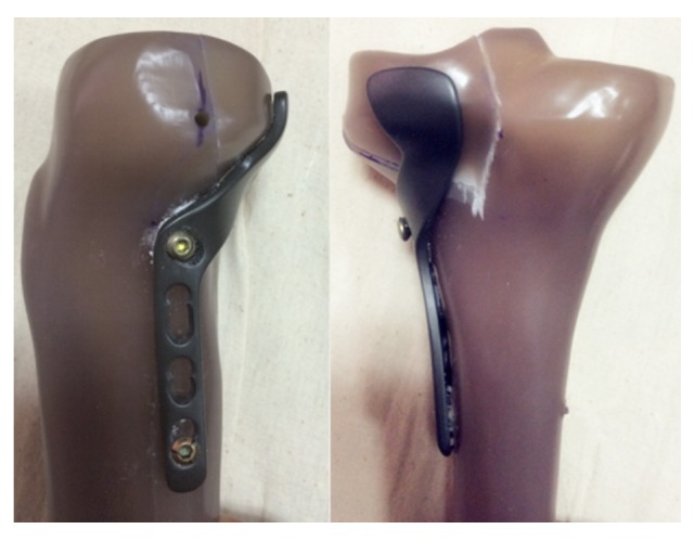
Diagram of the novel plate for posterolateral tibial plateau fractures in design and entity.
Material and Methods
Materials
Computer tomography (CT) scanning data of the knee joint in patients was randomly selected from the same CT (Siemens company, 64 row, Germany) database used by our hospital. It included conventional sagittal and coronal and axial scans. Scanning layer thickness was 1 mm, and standard data with no knee or tibial deformities were used. Exclusion criteria for scan samples included medical history of trauma, surgery, arthritis, and obvious bone changes (including osteoporosis, hyperosteogeny, osteophyte formation). There were 98 cases (left and right knees of 49 patients), including 33 males and 65 females. The average age was 48.13 years (range 16 years to 72 years).
Observation target
Coordinate system
Our goal was to establish the tibial plateau coordinate system according to the method reported by Kuwano et al. [10]: using tibial 3-dimensional imaging to determine the long axis of the tibia for the Z axis (Figure 2) to ensure that the cross section of the scan is perpendicular to the Z axis. Then, in CT cross-sectional images, we determined the midpoint (point C) of the posterior cruciate ligament (PCL) of the knee joint, which is attached at the tibial plateau posterior intercondylar area posterolateral point (point A) and at the anterior point (point B) (Figure 3). Then, we used cross-sectional images of the low plane to calibrate the 1/3 point of the medial tibial tuberosity (Figure 4), connecting the midpoint of the PCL (point C) and the 1/3 point of the medial tibial tuberosity to constitute the anteroposterior plane of the tibial plateau (sagittal plane of tibial plateau). The plane that was perpendicular to the sagittal plane of the tibial plateau is the coronal plane of the tibial plateau. In this manner, we set up a 2-dimensional coordinate system of the cross section (Figure 5).
Figure 2.
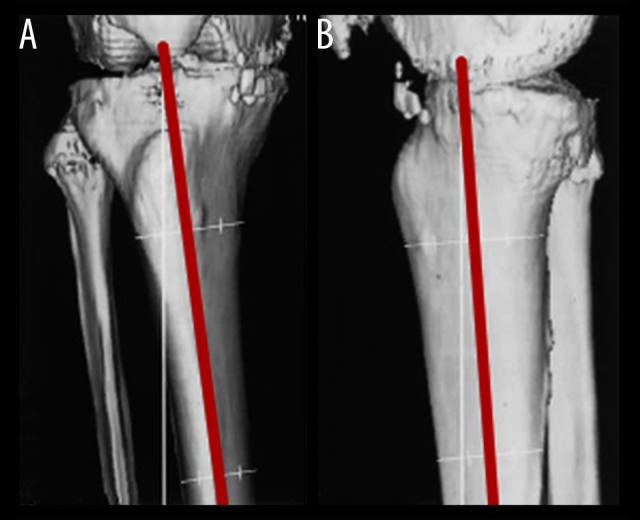
To ensure the consistency of the long axis and the Z axis of the tibia by correcting 3-dimensional imaging of the proximal tibiofibular and distal femur; (A) anteroposterior view; (B) lateral view.
Figure 3.
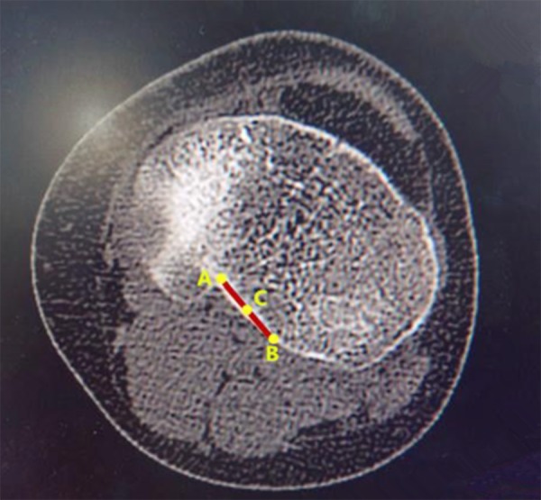
The midpoint (point C) of the posterior cruciate ligament, which is attached at the tibial plateau posterior intercondylar area posterolateral point (point A) and at the anterior point (point B).
Figure 4.
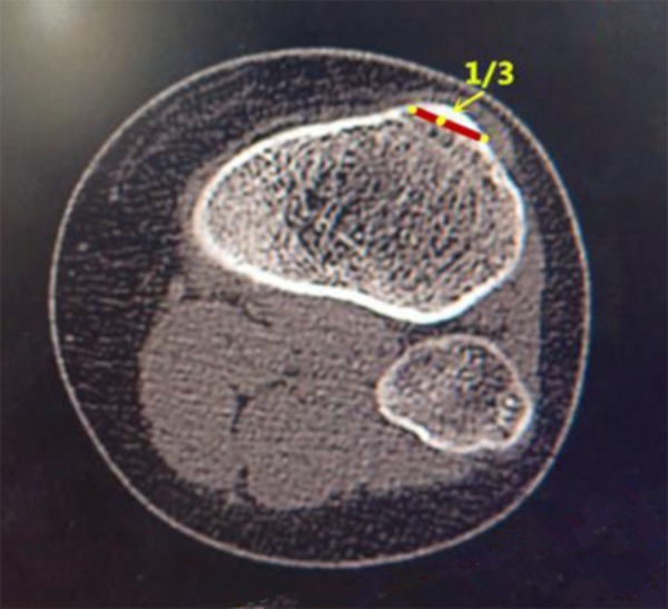
The 1/3 point of medial tibial tuberosity.
Figure 5.
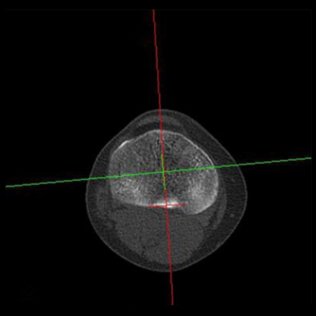
The 2-dimensional coordinate system of the cross section.
Cross section measurement
Reading the cross-sectional scan image from proximal to distal tibia, the first image that appeared on the lateral tibial plateau was defined as the Zero plane, i.e., the proximal edge of the tibial plateau. On this first image of the complete lateral tibial plateau, we marked 2 axes. The first axis was parallel to the coronal plane of the tibial plateau, and tangent to the posterior margin of the lateral tibial plateau (tangent point marked as P). The second axis was parallel to the sagittal plane of the tibial plateau, and tangent to the lateral margin of the tibial plateau (tangent point marked as L). We then marked 2 perpendiculars of the sagittal plane through points P and L, respectively (vertical point denoted as P’ and L’ respectively). LL’ represents the width of the lateral tibial plateau. PP’ represents the width of the posterolateral tibial plateau to the sagittal plane of the tibial plateau (Figure 6). Scanning continued to the first image of the tibiofibular joint, where the vertex of the tibiofibular joint was marked as S, and the perpendicular line of the sagittal plane of the tibial plateau was marked through point S (vertical point denoted as S’). SS’ represents the width from the proximal tibiofibular joint to the sagittal plane of the tibial plateau (Figure 7). We continued to measure the proximal posterolateral tibial bone cortex angle in the lower cross-sectional images (Figure 8), taking six evenly distributed points along the vertical distance from the lowest point of the proximal tibiofibular joint at 5, 10, 15, 20, 25, and 30 mm. Those angles were denoted as C1, C2, C3, C4, C5, and C6, respectively.
Figure 6.
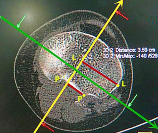
LL’ represents the width of the lateral tibial plateau; PP’ represents the width from the posterolateral tibial plateau to the sagittal plane of the tibial plateau.
Figure 7.
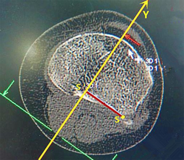
SS’ represents the width of the proximal tibiofibular joint to the sagittal plane of the tibial plateau.
Figure 8.
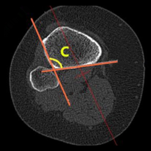
The proximal posterolateral tibial bone cortex angle.
Sagittal plane measurement
Scanning of the sagittal plane of the tibial plateau through point P was defined in the first image that appeared of the lateral tibial plateau (Figure 9). Here, point D was the vertex of the angle between the tibial plateau and the metaphysis slope, and point E was the concave point of the angle between the metaphysis slope and the tibial shaft. Angle DEF was the posterolateral slope-diaphysis angle, and DE was the length of the posterior lateral slope of the tibial plateau.
Figure 9.
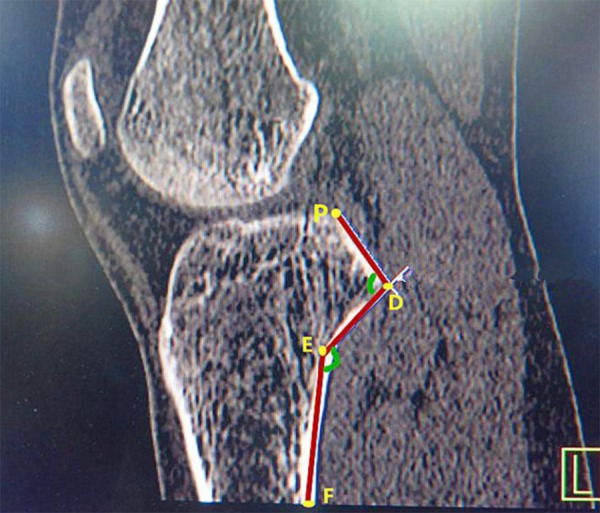
Posterolateral slope-diaphysis angle.
Statistical analysis
Statistical analysis was performed using SPSS 18.0 statistical software (SPSS Inc., Chicago, IL, USA). The K-S test was used to test the normality of the original data, and the result of the variable value of the normal distribution was expressed by x±s. Paired sample t-test was used to test the same parameters for male and female patients, and left and right knees. P<0.05 was defined as statistically significant. For Pearson correlation analysis between the width of the lateral tibial plateau and other length indicators, P<0.01 was considered statistically significant.
Results
Anatomy parameter results
The width of the lateral tibial plateau, width of the posterolateral tibial plateau to the sagittal plane of the tibial plateau, width of the proximal tibiofibular joint to the sagittal plane of the tibial plateau (3 length index) and proximal posterolateral tibial bone cortex angle and posterolateral slope-diaphysis angle (2 angle index) were all subject to normal distribution. Paired t-test of these indicators showed no statistically significant differences between the left and right sides (P>0.05). Paired t-test of the 3 length indices showed that the differences between males and females had statistical significance (P<0.05). The detailed data are shown in Tables 1 and 2.
Table 1.
Measurement results of anatomical parameters (mean ±SD).
| Right | Left | Total | t | P | |
|---|---|---|---|---|---|
| Width of lateral tibial plateau (LL’) | 3.53±0.23 | 3.51±0.28 | 3.52±0.25 | 0.358 | 0.722 |
| Width of the posterolateral tibial plateau to the sagittal plane of the tibial plateau (PP’) | 1.66±0.27 | 1.68±0.19 | 1.67±0.23 | 0.388 | 0.699 |
| Width of the proximal tibiofibular joint to the sagittal plane of the tibial plateau (SS’) | 2.67±0.38 | 2.77±0.34 | 2.72±0.36 | 1.258 | 0.25 |
| Proximal posterolateral tibial bone cortex angle 1 (∠C1) | 104.82±9.75 | 101.71±10.67 | 103.27±10.33 | 1.543 | 0.129 |
| Proximal posterolateral tibial bone cortex angle 2 (∠C2) | 105.04±9.63 | 99.88±8.91 | 102.46±9.88 | 1.900 | 0.063 |
| Proximal posterolateral tibial bone cortex angle 3 (∠C3) | 103.81±8.71 | 98.98±8.91 | 101.37±9.14 | 1.753 | 0.086 |
| Proximal posterolateral tibial bone cortex angle 4 (∠C4) | 104.13±10.87 | 97.76±8.71 | 100.75±10.29 | 1.680 | 0.101 |
| Proximal posterolateral tibial bone cortex angle 5 (∠C5) | 102.91±12.23 | 97.05±9.89 | 99.82±11.44 | 1.205 | 0.237 |
| Proximal posterolateral tibial bone cortex angle 6 (∠C6) | 104.86±14.55 | 97.77±9.89 | 101.02±12.74 | 0.920 | 0.376 |
| Posterolateral slope-diaphysis angle 1 (∠DEF1) | 147.46±9.57 | 150.53±6.15 | 149.01±8.17 | 1.878 | 0.067 |
| Posterolateral slope-diaphysis angle 2 (∠DEF2) | 147.45±8.42 | 148.21±13.85 | 147.80±11.44 | 0.128 | 0.900 |
| Posterolateral plateau-slope angle 3 (∠DEF3) | 143.20±6.69 | 143.20±6.69 | 143.20±6.51 | 0.432 | 0.674 |
Paired t-test is significant at the level of 0.05.
Table 2.
Measurement results of anatomical parameters (mean ±SD).
| Male | Female | Total | t | P | |
|---|---|---|---|---|---|
| Width of lateral tibial plateau (LL’) | 3.77±0.20 | 3.39±0.17 | 3.52±0.25 | 2.088 | 0.044 |
| Width of the posterolateral tibial plateau to the sagittal plane of the tibial plateau (PP’) | 1.76±0.20 | 1.63±0.24 | 1.67±0.23 | 2.052 | 0.048 |
| Width of the proximal tibiofibular joint to the sagittal plane of the tibial plateau (SS’) | 3.02±0.29 | 2.57±0.29 | 2.72±0.36 | 2.114 | 0.042 |
| Proximal posterolateral tibial bone cortex angle 1 (∠C1) | 102.58±10.95 | 103.63±9.99 | 103.27±10.33 | 0.346 | 0.731 |
| Proximal posterolateral tibial bone cortex angle 2 (∠C2) | 102.67±9.77 | 102.35±9.94 | 102.46±9.88 | 0.132 | 0.896 |
| Proximal posterolateral tibial bone cortex angle 3 (∠C3) | 102.42±9.61 | 100.81±8.83 | 101.37±9.14 | 0.607 | 0.547 |
| Proximal posterolateral tibial bone cortex angle 4 (∠C4) | 102.00±11.10 | 100.00±9.69 | 100.75±10.29 | 0.595 | 0.557 |
| Proximal posterolateral tibial bone cortex angle 5 (∠C5) | 100.62±12.79 | 99.37±10.58 | 99.82±11.44 | 0.225 | 0.825 |
| Proximal posterolateral tibial bone cortex angle 6 (∠C6) | 103.19±14.25 | 99.94±11.77 | 101.02±12.74 | 0.534 | 0.616 |
| Posterolateral slope-diaphysis angle 1 (∠DEF1) | 147.21±10.29 | 150.00±6.52 | 149.01±8.17 | 0.883 | 0.384 |
| Posterolateral slope-diaphysis angle 2 (∠DEF2) | 145.72±15.16 | 149.25±7.06 | 147.80±11.44 | 0.030 | 0.977 |
| Posterolateral plateau-slope angle 3 (∠DEF3) | 146.56±6.09 | 140.45±5.85 | 143.20±6.51 | 2.165 | 0.062 |
Paired t-test is significant at the level of 0.05
Correlation analysis
Pearson bivariate correlation analysis showed that, between the width of the lateral tibial plateau and the other 2 length indices, there is a moderate correlation (Pearson correlation coefficients were 0.535 and 0.577, respectively). Specific analysis results are shown in Table 3.
Table 3.
Correlation analysis between TL and other length parameters.
| Item | Pearson’s correlation coefficient | P |
|---|---|---|
| LL’-PP’ | 0.535 | <0.001 |
| LL’-SS’ | 0.577 | <0.001 |
Correlation is significant at the level of 0.01 (2-tailed).
Discussion
Our study showed that there should be no difference between the left and right knees in the design of a fracture repair plate. There was no sex difference in the angle and curvature. However, the plates used should be distinguished in size because there were statistically significant differences of the 3 length indices between men and women (P<0.05). By measuring the width of the lateral tibial plateau, width of the posterolateral tibial plateau to the sagittal plane of the tibial plateau, and width of the proximal tibiofibular joint to the sagittal plane of the tibial plateau, the width of the internal fixation head can be determined. By measuring the length of the posterior lateral slope of the tibial plateau and the posterolateral slope-diaphysis angle, the length and radian of the internal fixation head can be determined. Finally, by measuring the proximal posterolateral tibial bone cortex angle, the radian between the head and the body of the internal fixation can be determined. In addition, our results showed that the length of the lateral tibial plateau and other length indicators are correlated. Therefore, the size of the internal fixation plate can be estimated according to preoperative CT scan. The novel plate created will apply to most patients based on our data.
Advantage of the novel plate for posterolateral tibial plateau fractures
Our novel plate has several advantages. The operative approach is safe, and exposure is good, the supine posture is easy to facilitate, and it is easy to evaluate the results of intraoperative fluoroscopy. No important nerves and blood vessels exist near the incision. And operative injury is low, and it does not affect the stability of the knee. Additionally, the internal fixation is simple, can shorten the operative time and reduce intraoperative bleeding. Related mechanics research [11] has demonstrated the anti-load performance of a rear support plate. The head of the novel plate design is similar to the anti-sliding support plate and has good mechanical properties. The novel internal fixation fixes on the anterior tibial lateral cortex posteriorly, and when other lateral fractures of the tibial plateau exist, it does not affect anterolateral fixation placement. Finally, the removal of the internal fixation is simple after fracture healing.
Prospect of research
Through the image studies of the space structure around the proximal tibiofibular joint, we obtained the geometric features of the joint. Based on these results, we developed a novel plate for posterolateral tibial plateau fractures (Figure 1) and applied for a patent (Patent No. CN201520195596.5). The new plate was placed beneath the proximal tibiofibular joint anterolaterally, with the oblique part of the plate immediately adjacent to the posterolateral fragments inferoposteriorly, without inserting a screw. A screw was then inserted through the sliding hole located at the junction of oblique and straight parts to reduce and compact the fragments further by sliding the plate superoanteriorly.
In the future, finite element analysis and biomechanics research will be undertaken to determine the reliability of the new plate. A clinical series will be conducted to provide a dependable basis for the clinical application of this new treatment option for posterolateral tibial plateau fractures.
Conclusions
Advancing the understanding of 3-dimensional structure of the proximal tibiofibular joint and the novel design of the plate will provide a new perspective for the treatment of posterolateral tibial plateau fractures.
Footnotes
Source of support: Departmental sources
Conflict of interest
None.
References
- 1.Hoekstra H, Rosseels W, Luo CF, Nijs S. A combined posterior reversed L-shaped and anterolateral approach for two column tibial plateau fractures in Caucasians: A technical note. Injury. 2015;46(12):2516–19. doi: 10.1016/j.injury.2015.10.014. [DOI] [PubMed] [Google Scholar]
- 2.Jiwanlal A, Jeray KJ. Outcome of posterior tibial plateau fixation. J Knee Surg. 2016;29(1):34–39. doi: 10.1055/s-0035-1564729. [DOI] [PubMed] [Google Scholar]
- 3.Perry CR, Evans LG, Rice S, et al. A new surgical approach to fractures of the lateral tibial plateau. J Bone Joint Surg Am. 1984;66(8):1236–40. [PubMed] [Google Scholar]
- 4.Yu B, Han K, Zhan C, et al. Fibular head osteotomy: A new approach for the treatment of lateral or posterolateral tibial plateau fractures. Knee. 2010;17(5):313–18. doi: 10.1016/j.knee.2010.01.002. [DOI] [PubMed] [Google Scholar]
- 5.Sassoon AA, Torchia ME, Cross WW, et al. Fibular shaft allograft support of posterior joint depression in tibial plateau fractures. J Orthop Trauma. 2014;28(7):e169–75. doi: 10.1097/BOT.0000000000000020. [DOI] [PubMed] [Google Scholar]
- 6.Biggi F, Di Fabio S, D’Antimo C, Trevisani S. Tibial plateau fractures: Internal fixation with locking plates and the MIPO technique. Injury. 2010;41(11):1178–82. doi: 10.1016/j.injury.2010.08.001. [DOI] [PubMed] [Google Scholar]
- 7.Carlson DA. Bicondylar fracture of the posterior aspect of the tibial plateau. A case report and a modified operative approach. J Bone Joint Surg Am. 1998;80(7):1049–52. doi: 10.2106/00004623-199807000-00014. [DOI] [PubMed] [Google Scholar]
- 8.Stahel PF, Smith WR, Morgan SJ. Posteromedial fracture fragments of the tibial plateau: An unsolved problem? J Orthop Trauma. 2008 Aug;22(7):504. doi: 10.1097/BOT.0b013e3181846ca2. author reply 504–5. [DOI] [PubMed] [Google Scholar]
- 9.Madadi F, Eajazi A, Madadi F, et al. Adult tibial shaft fracture-different patterns, various treatments and complications. Med Sci Monit. 2011;17(11):CR640–45. doi: 10.12659/MSM.882049. [DOI] [PMC free article] [PubMed] [Google Scholar]
- 10.Kuwano T, Urabe K, Miura H, et al. Importance of the lateral anatomic tibial slope as a guide to the tibial cut in total knee arthroplasty in Japanese patients. J Orthop Sci. 2005;10(1):42–47. doi: 10.1007/s00776-004-0855-7. [DOI] [PubMed] [Google Scholar]
- 11.Zhang W, Luo CF, Putnis S, et al. Biomechanical analysis of four different fixations for the posterolateral shearing tibial plateau fracture. Knee. 2012;19(2):94–98. doi: 10.1016/j.knee.2011.02.004. [DOI] [PubMed] [Google Scholar]


