Abstract

Understanding the electrochemical behavior of Pt at the solid/liquid interface is of significant importance for the development of efficient electrochemical devices, such as fuel cells and water electrolyzers. In this work, the evolution of the surface morphology of a polycrystalline platinum under potential cycling conditions was investigated by in situ electrochemical atomic force microscopy (EC-AFM). After 50 cycles between 0.05 and 1.8 V in 0.1 M H2SO4, the Pt surface is coarsened and nanoparticles of several nanometers appear on the surface. The critical upper and lower potentials for the formation of nanoparticles are found to be 1.8 and 0.8 V, respectively. The in situ AFM observation coupled with Cyclic Voltammerty reveals the periodic disappearance and reappearance of the nanoparticles, based on which the formation of nanoparticles is attributed to the deposition of dissolved Pt from solution, and a model for the nanoparticle formation is proposed. While the formation of a thick oxide layer is a prerequisite, the reduction process is found to have a strong influence on Pt nanoparticle formation as well. This investigation provides a visualization of the Pt electrode surface under electrochemical control in a large potential window, enabling a broader understanding of the Pt electrode roughening mechanisms.
Introduction
An atomic level understanding of the surface oxidation and subsequent reduction processes at platinum electrodes is vital since Pt is one of the most widely used metals in the field of applied electrochemistry. Platinum is used as a cathode and anode material in acid fuel cells and water electrolyzers due to its excellent performance as a catalyst, as well as in many electroanalytical devices. However, the electrochemical stability of Pt is compromised by the formation of platinum oxides and their reduction, causing serious problems for practical operation.1,2 Platinum oxidation and subsequent reduction happen during stop–start cycles in practical devices and are typically simulated by continuous potential cycling in laboratory experiments. Much effort has been spent to prevent or diminish the degradation of Pt by enhancing the Pt–carbon interaction or by alloying Pt with other metals.3,4 Simultaneously, it is of significant importance to explore the underlying fundamental mechanisms for the electrochemical processes at Pt electrodes during potential cycling. The onset of the oxidation of polycrystalline Pt is at around 0.8 V. The formation of a 2D platinum peroxide phase on Pt(111) single crystals was identified in the 1.0–1.1 V potential region by in situ Raman spectroscopy.5 During further surface oxidation, a 3D α-PtO2 oxide forms at 1.15 V via the so-called place-exchange mechanism, in which surface Pt atoms change their position with the oxygen derived from the oxidation of water. After reduction, some of these Pt atoms do not return to their original sites, rendering the process structurally irreversible and causing the roughening of the Pt surface. Dissolution of Pt electrodes during the surface roughening is an important cause for electrode instability. Pt dissolution in perchloric acid was investigated by online inductively coupled plasma mass spectrometry (ICP-MS), and it was found that the concentration of Pt ions in the solution depends on the dissolution potential and on the orientation of the Pt electrode.6 By utilizing an electrochemical scanning flow cell coupled to ICP-MS, Topalov et al. showed that under cycling conditions the dissolution mainly occurs in the cathodic sweep, i.e., during the reduction of the surface oxide, with the amount of dissolved Pt increasing with the upper potential limit.7
In situ observation of electrochemically induced roughening of Pt electrodes has been studied by scanning probe microscopy, either using scanning tunneling microscopy (STM) or atomic force microscopy (AFM). The surface roughening phenomenon of Pt single crystals after multiple oxidation–reduction cycles has been observed by electrochemical (EC)-STM.8−11 More recently, in situ EC-STM investigation of Pt(111) during oxidation–reduction cycles revealed the formation of Pt monatomic islands.12 After prolonged oxidation–reduction cycles, the islands contribute equally to the electrochemical signal in the hydrogen region and to the root-mean-square roughness derived from the STM images.13 From in situ grazing incidence small-angle X-ray scattering (GISAXS) measurements of a Pt(111) electrode in perchloric acid, it was concluded that the formation of Pt islands during oxidation–reduction cycles resembles the 3D growth behavior of Pt(111) during deposition and erosion in ultrahigh vacuum.11 Due to the requirement of conductivity, EC-STM experiments are normally performed with an upper limit of 1.3 V. The utilization of EC-AFM enables the visualization of the dynamic process at the Pt surface in a wider potential range, and additionally, EC-AFM can be used to study processes on the surface that might not be ideal for STM, such as the imaging of a Pt film on carbon14 or Pt nanoparticles.15 However, there are only a few reports about the investigation of Pt electrodes using EC-AFM.
Here, we present an in situ EC-AFM study of the surface changes observed on a flame-annealed polycrystalline Pt electrode in sulfuric acid electrolyte subjected to repeated oxidation–reduction cycles. The most significant observation is the formation of Pt nanoparticles on the surface after multiple sweeps to sufficiently high potential. We show that the observation of these nanoparticles depends on the creation of Pt ions in the solution, which act as the source of nanoparticle generation during the reductive sweep, provided the sweep goes negative enough to reduce the surface oxide and provided that the Pt ions are not given the opportunity to diffuse away. This mechanism of surface roughening through (extensive) redeposition of dissolved platinum appears to be specific to polarization at higher anodic potential, a regime that was not included in previous studies of Pt coarsening studied by GISAXS,11 EC-STM,13 or EC-AFM.15 Our results illustrate the ability of in situ EC-AFM as a tool to investigate the coarsening behavior of the Pt electrode under electrochemical conditions and provide new insights into the phenomena taking place on the Pt electrode during oxidation–reduction cycles.
Experimental Section
The in situ AFM experiments were carried out in an electrochemical AFM cell that is made of PEEK. Before assembly, the cell components were cleaned by sonication in ethanol and Millipore Milli-Q water (resistivity 18.2 MΩ cm), respectively, and then blow dried in air. Prior to each experiment, the working electrode Pt foil (99.9%, MaTeck) was flame-annealed and quenched with Milli-Q water before assembling into the EC-AFM cell. A Ag/AgCl (3 M KCl) electrode (WPI) was used as the reference electrode, and the counter electrode was a Pt wire. All the potentials in this article are reported with respect to a reversible hydrogen electrode (RHE). A potentiostat (μAutolab type III) was coupled with the AFM (JPK NanoWizard 3) to control the electrochemical conditions during the experiments. The sweep rate was set to 100 mV/s for all the cyclic voltammetry measurements. The AFM scan rate was 1 Hz, and all the images were obtained using tapping mode, to minimize the damage to the electrode. The tips used were purchased from Bruker (SNL, resonance frequency: 65 kHz, spring constant: 0.35 N/m). Images were taken either at 0.5 V after potential cycling or during cycling simultaneously with cyclic voltammetry (CV). The electrolyte was prepared from H2SO4 (Merk Ultrapur, 96%), which was neither completely degassed nor refreshed during the experiment.
Results and Discussion
Cyclic Voltammetry of the Flame-Annealed Pt in an EC-AFM Cell
The blank cyclic voltammogram of the flame-annealed Pt electrode in 0.1 M H2SO4 in the EC-AFM cell is shown in Figure 1. The red curve, measured in a N2-protected atmosphere, shows the hydrogen region between 0.05 and 0.26 V with peaks at 0.12 and 0.21 V corresponding to the adsorption of hydrogen at (110) and (100) steps, respectively. The oxidation of the Pt occurs when the potential increases to 1.0 V, and the sharply increased current above 1.45 V indicates the evolution of oxygen. The negative-going sweep displays the reduction peak of the Pt oxide at 0.64 V. There are two types of Pt oxide, α-Pt oxide, which forms under moderate oxidation conditions, and β-Pt oxide, which forms under more severe oxidation conditions and which has a porous structure.16,17 The β-Pt oxide is expected to be reduced at a more negative potential than the reduction of the α-Pt oxide, which normally takes place at around 0.75 V.18 The peak at 0.64 V is attributed to the reduction of a mixture of α- and β-Pt oxides. As the AFM measurement is performed in an open EC cell without removal of the oxygen from the electrolyte, the black curve shows the CV recorded during the experiment under ambient atmosphere. As compared with the experiment under N2, the presence of oxygen leads to a small tilting of the curve (due to residual oxygen reduction) and the appearance of a small anodic peak at about 0.95 V. We have performed also in situ EC-AFM measurements in which N2 was purged prior to the experiment, and the observations to be described below were the same.
Figure 1.
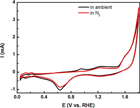
Cyclic voltammogram of Pt in 0.1 M H2SO4 in ambient atmosphere (black curve) and in N2-saturated electrolyte (red curve). Scan rate is 100 mV/s.
AFM Imaging of Pt Surface after Potential Cycling
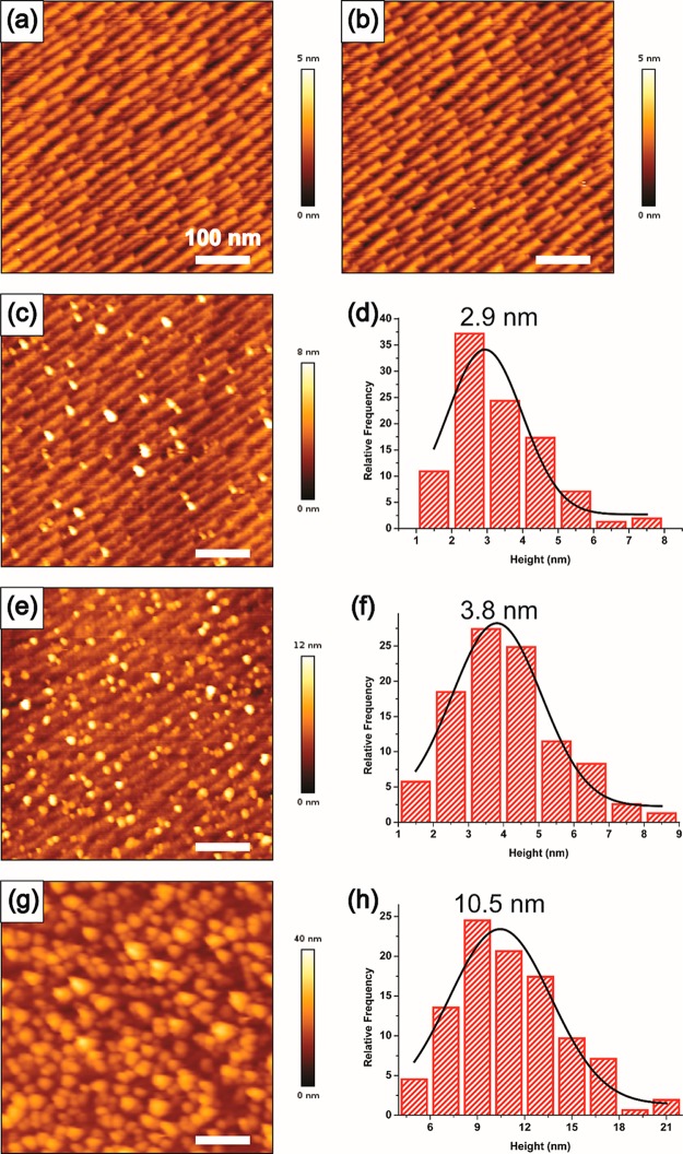
Figure 2 shows in situ EC-AFM topographical images of the platinum surface after potential cycling for 50 times in different potential ranges. The topography in Figure 2a shows terraces with sawtooth-shaped steps covering the whole imaging area, which we assign to a faceting induced during the flame annealing of the polycrystalline sample (its orientation is not defined in the experiment). There was no control over the orientation of the surface that was imaged, but the electrochemical phenomena are basically the same on all electrodes. Figure 2a and b show the images obtained after cycling 50 times between 0.05 and 1.0 V and between 0.05 and 1.5 V, respectively. In all images, the potential of the Pt working electrode was held at 0.5 V. Potential excursion to 1.5 V does not bring obvious changes to the surface as compared with the image obtained after cycling to 1.0 V. Previous EC-STM investigations showed the formation of Pt islands on the Pt(111) surface after cycling five times between 0 and 1.5 V in H2SO4 electrolyte,8 but this roughening of the surface is not observed in our EC-AFM experiment, which we attribute to the polycrystalline nature of the sample and the lower resolution of the AFM as compared to STM. However, extending the upper potential limit to 1.8 V during the 50 oxidation–reduction cycles leads to a visible coarsening of the Pt surface through the appearance of nanoparticles on the surface (Figure 2c). The average size of the nanoparticles is estimated to be 2.9 nm by a statistical analysis at least 150 particles from the image. On increasing the upper potential to 2.0 V, both the roughness of the surface and the number and the size of the nanoparticles increase (Figure 2e and f). The t test result shows that the population mean of Figure 2f is significantly different from that of Figure 2d at the 0.05 level of significance. Further sweeping to a potential of 2.5 V results in violent oxygen evolution and leads to the formation of nanoparticles with an average size of 10.5 nm covering the whole surface (Figure 2g and h). Increasing the upper potential during the cycling therefore increases the size of the nanoparticles, suggesting that the extensive oxidation of the electrode promotes the formation of the nanoparticles.
Figure 2.
AFM height images of the Pt electrode surface after potential cycling between (a) 0.05–1.0 V, (b) 0.05–1.5 V, (c) 0.05–1.8 V, (e) 0.05–2.0 V, and (g) 0.05–2.5 V. The height distribution of the nanoparticles on the surface is shown in (d), (f), and (h). The scale bars are 100 nm.
To investigate the minimum upper potential needed for the observation of the nanoparticles, experiments were carried out by increasing the upper potential in 0.1 V steps while keeping the lower potential at 0.05 V. Figure 3 shows that after potential cycling between 0.05 and 1.7 V (Figure 3a) no particles are observed, but the surface shows the appearance of nanoparticles after cycling up to 1.8 V (Figure 3b). Therefore, the minimum upper potential for the formation of nanoparticles under the current experimental conditions is between 1.7 and 1.8 V. Similarly, there is a maximum lower potential to observe nanoparticles, which is found to be 0.8 V, as illustrated in Figure 3c and d. Accordingly, to observe the formation of the nanoparticles, the potential cycling range should be set beyond the window of 0.8–1.8 V.
Figure 3.
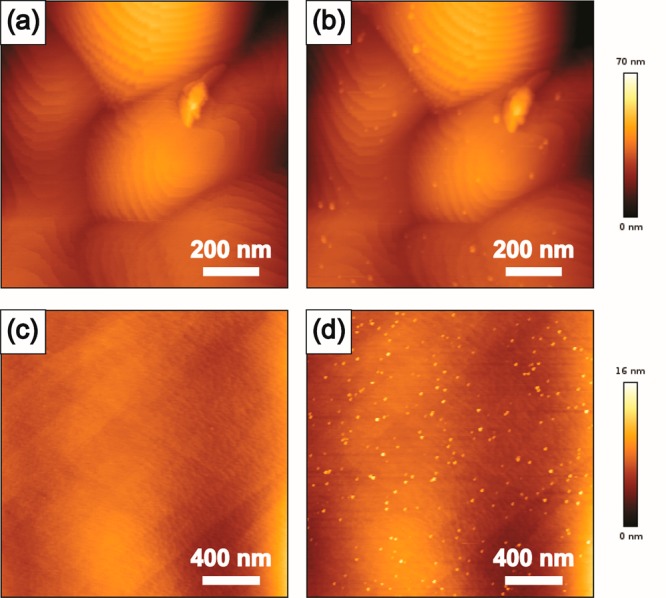
AFM height images of the Pt electrode surface after potential cycling between (a) 0.05–1.7 V, (b) 0.05–1.8 V, (c) 0.9–1.8 V, and (d) 0.8–1.8 V. Note that the scale is not the same in these images.
In Situ AFM Observation of the Nanoparticles during Potential Cycling
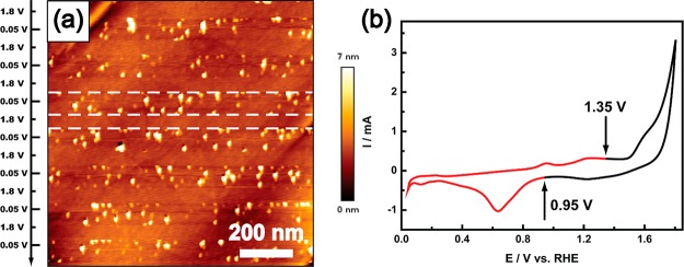
To further clarify the formation of the nanoparticles, in situ EC-AFM imaging of the Pt surface was performed simultaneously with the potential cycling. In Figure 4a, the tip is scanned from top to bottom while the potential is cycled. Two different strips or areas can be observed in the image, bordered by the white dashed lines. Nanoparticles are observed in one strip, but no nanoparticles are observed in the neighboring strip. Scanning positively, the nanoparticles disappear above 1.35 V and reappear again in the subsequent negative-going scan below 0.95 V. The observation of nanoparticles is indicated by the red line in the corresponding cyclic voltammogram in Figure 4b. No nanoparticles are observed on the surface in the black part of the CV. In order to rule out the possibility that the nanoparticles are detached from the surface due to the interference of the AFM tip, an experiment was performed by keeping the potential at 1.4 V for 5 min, on a surface that contained nanoparticles. The AFM image obtained after the treatment showed no nanoparticles on the surface (Figure S1). Moreover, it is found that potential cycling between 0.05 and 1.2 V reduces the number of nanoparticles and their size shrinks. Cycling between 0.05 and 1.4 V removes the nanoparticles on the Pt surface altogether, but they reappear after cycling between 0.05 and 1.8 V, confirming the above-mentioned minimum upper potential for the formation of nanoparticles (see Figure S2). On the basis of these observations we conclude that the nanoparticles are indeed Pt nanoparticles and that the onset of the nanoparticle formation occurs at 0.95 V, in agreement with the onset of Pt ion production due to the reduction of the Pt oxide as studied by online ICP-MS.7,19 The oxidation of Pt nanoparticles begins at about 1.2 V, leading to their decrease in number and size during potential cycling between 0.05 and 1.2 V, and they completely disappear when cycling up to 1.4 V. Moreover, there is no significant effect of the scanning tip in the removal of the nanoparticles. These results show that the Pt nanoparticles are in full electronic contact with the working electrode, and hence their oxidation state varies with the potential in the same way as the rest of the platinum surface. We note that recent work has shown that there might be OH existing on the steps in a platinum (nanoparticle) surface at 0.5 V.20,21
Figure 4.
(a) AFM height image of the Pt surface during potential cycling between 0.05 and 1.8 V illustrating the potential-dependent formation of the nanoparticles. The y axis gives the potential during the potentiodynamic cycling. (b) Corresponding CV of the Pt electrode. The red part of the CV shows the potentials for which the AFM image shows nanoparticles on the surface, while in the black part no nanoparticles are observed.
The upper potential of our experiment is within the potential window in which oxygen is generated. The presence of oxygen in the electrolyte may enhance Pt dissolution and Pt ion formation.22−24 Reduction of oxygen in the negative-going sweep can produce hydroxyl radicals (OH•) according to reaction 1.25 It has been suggested by Percival et al. that highly oxidizing OH• is responsible for the Pt dissolution during the oxygen reduction reaction. In our experiment, the formation of Pt nanoparticles starts at 0.95 V vs RHE at pH 1, a potential higher than the hydroxyl formation potential. The investigation from Noël et al. reveals the important role of hydroxyl radical for platinum dissolution; however, they found no appreciable dissolution of Pt even after a long sequence of potential pulses in acidic solutions (pH ≤ 2.5).26
| 1 |
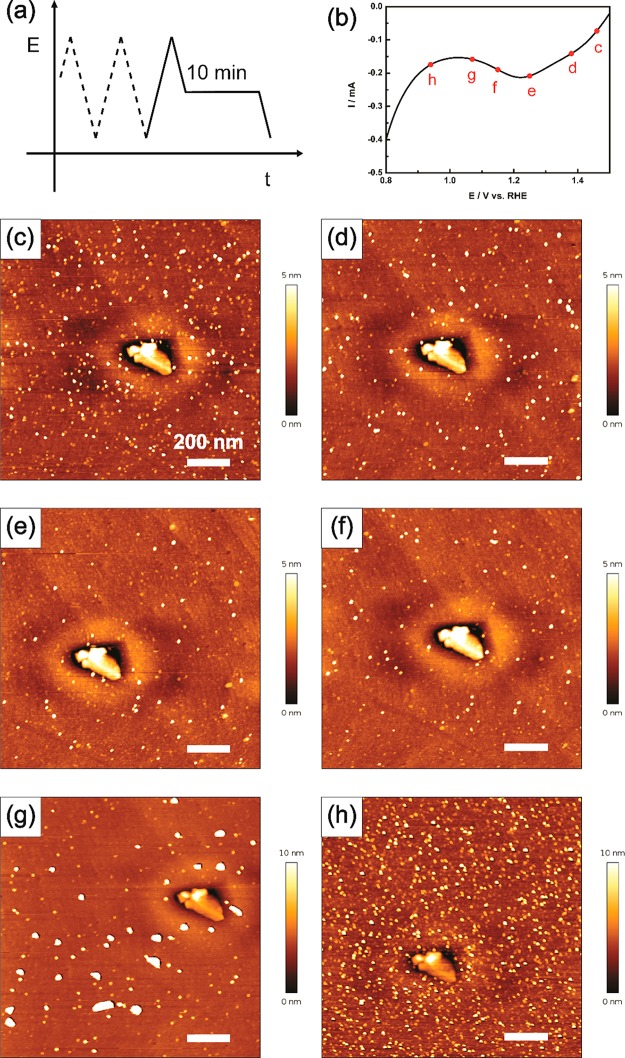
Our interpretation of the potential limits for nanoparticle formation is that while the existence of thick Pt oxide is the precondition for the formation of Pt nanoparticles, the nanoparticles are actually formed during the reductive sweep. Figure 5 shows results of experiments in which during the negative scan the potential is held at a certain value (“the stopping potential”) for 10 min before continuing to 0.05 V (Figure 5a); the six potentials are labeled in the CV curve (Figure 5b). The six surface images shown in Figure 5c–h are obtained (at 0.5 V) after following this protocol for the different stopping potentials. An area with what appears to be a triangular defect structure was imaged for comparison; however, the triangles in the AFM images are not in the exact same position due to thermal drift. It is observed that as the stopping potential decreases from Figure 5c to e, the number of Pt nanoparticles decreases as well. Figure 5e and f have a similar density of nanoparticles. As seen from the enlarged CV curve in Figure 5b, stopping potentials c to f are within the potential window where the Pt oxide is reduced, creating Pt ions in solution at the same time.7,19,27 Once the Pt ions are formed next to the Pt electrode, diffusion will carry them away from the surface if further reduction does not take place, which explains why fewer nanoparticles are observed on the surface in Figure 5c to e. Interestingly, when the potential is held at 1.07 V for 10 min, large nanoparticles with a height of up to 30 nm appear on the surface, as shown in Figure 5g. By contrast, when the stopping potential is 0.94 V for 10 min, a very large amount of small nanoparticles deposit on the surface (Figure 5h). As stated before, 0.95 V is the potential at which nanoparticles begin to appear during the cycling, which means that at around 0.95 V the nucleation of Pt nanoparticles starts. Holding the potential at 0.94 V for 10 min provokes the instantaneous nucleation of Pt, which leads to the formation of a substantial number of small Pt nanoparticles. On the other hand, holding the potential at 1.07 V, there is a very small number of nucleation sites, and as a result, the nanoparticles grow bigger than in the case of a larger number of nucleation sites. These observations confirm a nucleation and growth mechanism of nanoparticle formation in which the number of nucleation sites depends on the extent to which the Pt oxide has been reduced, and the growth of the Pt nanoparticles is influenced by the diffusion of dissolved Pt ions away from the electrode surface.
Figure 5.
(a) Potential protocol used to control the formation of Pt nanoparticles on the surface. (b) The six potential values chosen as the stopping potential, which are 1.46, 1.38, 1.25, 1.15, 1.07, and 0.94 V, respectively. (c–h) AFM height images of the Pt surface obtained after applying the protocol corresponding to points c–h in (b). The scale bars are 200 nm.
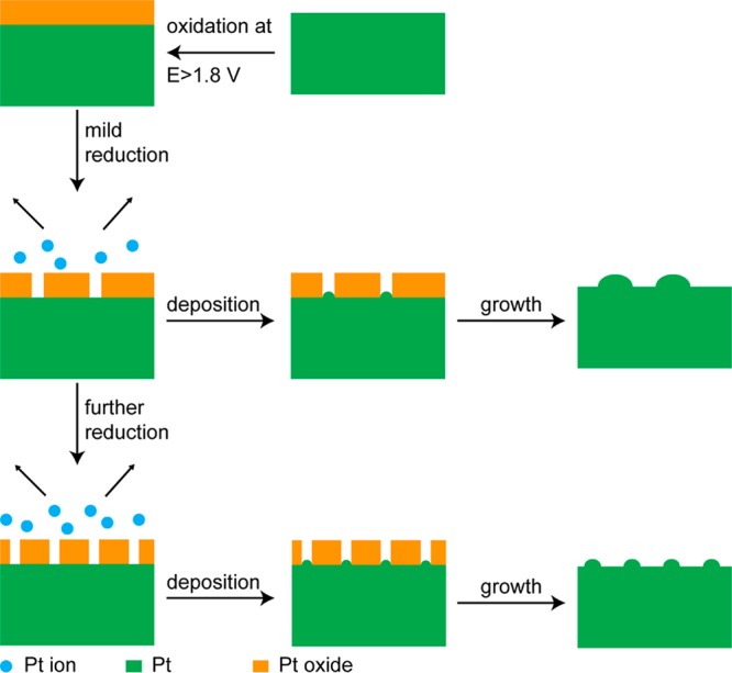
Based on our observations, a model for the formation of nanoparticles is proposed, as illustrated in Scheme 1. First, the Pt surface is oxidized at a potential higher than 1.8 V, which forms a thick Pt oxide layer. In the negative scan, reduction of the oxide leads to the formation of Pt ions close to the surface, which deposit as Pt nanoparticles in the further reduction process. The minimum potential of 1.8 V is assumed to be related to a minimum oxide thickness that generates a minimum concentration of dissolved Pt near the electrode during the reduction of the oxide. The formation of the nanoparticles strongly depends on the extent to which Pt oxide is reduced. If only a small amount of oxide is reduced, this leads to limited nucleation sites for Pt deposition. Therefore, fewer but larger nanoparticles are found on the surface in this case. When the Pt oxide is further reduced, more nucleation sites are generated before the massive deposition of Pt, leading to many small nanoparticles. In the following potential cycle, the Pt surface is oxidized at high potential, which forms the thick oxide layer again. The continuous oxidation and reduction creates the oxide layer and Pt ions, which leads to the periodical behavior of the disappearance and reappearance of nanoparticles as observed in the in situ AFM image shown in Figure 4.
Scheme 1. Proposed Mechanism for Pt Nanoparticle Formation on the Surface in H2SO4 Electrolyte.
Conclusion
In summary, we have used in situ EC-AFM to investigate the formation of Pt nanoparticles on the surface of a polycrystalline flame-annealed Pt electrode in 0.1 M H2SO4, during various potential excursions between 0.05 and 2.5 V. The size and the number of the nanoparticles increase with the upper potential limit. A minimal upper potential of 1.8 V was observed, which we ascribe to the existence of a thick oxide layer as a precondition for the formation of the Pt nanoparticles in the subsequent negative-going scan. Reduction of this oxide layer generates dissolved Pt ions, which will start to electrodeposit by nucleation and growth on the surface at about 0.95 V, this potential being related to the reduction of the surface oxide. A thick enough oxide and its subsequent reduction are therefore vital to the Pt nanoparticle formation. We note that this mechanism of surface roughening is different from the mechanism studied recently by in situ GISAXS and EC-STM, which studied platinum surface roughening in a more limited potential window in which the redeposition of dissolved Pt (presumably) plays a minor role. The generation of nanoparticles is observed when cycling a Pt electrode in acidic electrolyte, which is the most common electrolyte used in Pt electrochemistry. It will be of great interest to study the phenomenon in other electrolytes, including buffer solutions and alkaline media. This study also demonstrates the important role that in situ EC-AFM can play in investigating (dynamic) morphological changes of Pt under electrochemical control, which will ultimately help to understand and improve the performance of the Pt-based devices for electrochemical energy conversion and electroanalysis. Due to the ability to make observations of surface morphology in real space and time, we hope that our study will inspire more in situ EC-AFM investigations of electrochemical surfaces.
Acknowledgments
This work received partial support from Hitachi, Ltd. and Hitachi High-Technologies Corporation.
Supporting Information Available
The Supporting Information is available free of charge on the ACS Publications website at DOI: 10.1021/jacs.8b07452.
AFM images of Pt nanoparticles on the Pt electrode surface after potential holding and potential cycling (PDF)
The authors declare no competing financial interest.
Supplementary Material
References
- Borup R.; Meyers J.; Pivovar B.; Kim Y. S.; Mukundan R.; Garland N.; Myers D.; Wilson M.; Garzon F.; Wood D.; Zelenay P.; More K.; Stroh K.; Zawodzinski T.; Boncella J.; McGrath J. E.; Inaba M.; Miyatake K.; Hori M.; Ota K.; Ogumi Z.; Miyata S.; Nishikata A.; Siroma Z.; Uchimoto Y.; Yasuda K.; Kimijima K.-i.; Iwashita N. Chem. Rev. 2007, 107, 3904–3951. 10.1021/cr050182l. [DOI] [PubMed] [Google Scholar]
- Wang Y.-J.; Wilkinson D. P.; Zhang J. Chem. Rev. 2011, 111, 7625–7651. 10.1021/cr100060r. [DOI] [PubMed] [Google Scholar]
- Yu X.; Ye S. J. Power Sources 2007, 172, 145–154. 10.1016/j.jpowsour.2007.07.048. [DOI] [Google Scholar]
- Debe M. K. Nature 2012, 486, 43–51. 10.1038/nature11115. [DOI] [PubMed] [Google Scholar]
- Huang Y. F.; Kooyman P. J.; Koper M. T. Nat. Commun. 2016, 7, 12440. 10.1038/ncomms12440. [DOI] [PMC free article] [PubMed] [Google Scholar]
- Komanicky V.; Chang K. C.; Menzel A.; Markovic N. M.; You H.; Wang X.; Myers D. J. Electrochem. Soc. 2006, 153, B446–B451. 10.1149/1.2229284. [DOI] [Google Scholar]
- Topalov A. A.; Katsounaros I.; Auinger M.; Cherevko S.; Meier J. C.; Klemm S. O.; Mayrhofer K. J. J. Angew. Chem., Int. Ed. 2012, 51, 12613–12615. 10.1002/anie.201207256. [DOI] [PMC free article] [PubMed] [Google Scholar]
- Breuer N.; Funtikov A. M.; Stimming U.; Vogel R. Surf. Sci. 1995, 335, 145–154. 10.1016/0039-6028(95)00460-2. [DOI] [Google Scholar]
- Furuya N.; Shibata M. J. Electroanal. Chem. 1999, 467, 85–91. 10.1016/S0022-0728(99)00077-7. [DOI] [Google Scholar]
- Furuya N.; Ichinose M.; Shibata M. J. Electroanal. Chem. 1999, 460, 251–253. 10.1016/S0022-0728(98)00331-3. [DOI] [Google Scholar]
- Ruge M.; Drnec J.; Rahn B.; Reikowski F.; Harrington D. A.; Carlà F.; Felici R.; Stettner J.; Magnussen O. M. J. Am. Chem. Soc. 2017, 139, 4532–4539. 10.1021/jacs.7b01039. [DOI] [PubMed] [Google Scholar]
- Wakisaka M.; Asizawa S.; Uchida H.; Watanabe M. Phys. Chem. Chem. Phys. 2010, 12, 4184–4190. 10.1039/b923956a. [DOI] [PubMed] [Google Scholar]
- Jacobse L.; Huang Y.-F.; Koper M. T. M.; Rost M. J. Nat. Mater. 2018, 17, 277–282. 10.1038/s41563-017-0015-z. [DOI] [PubMed] [Google Scholar]
- Khalakhan I.; Choukourov A.; Vorokhta M.; Kúš P.; Matolínová I.; Matolín V. Ultramicroscopy 2018, 187, 64–70. 10.1016/j.ultramic.2018.01.015. [DOI] [PubMed] [Google Scholar]
- Onochi Y.; Nakamura M.; Hoshi N. J. Phys. Chem. C 2012, 116, 15134–15140. 10.1021/jp303563x. [DOI] [Google Scholar]
- Tremiliosi-Filho G.; Jerkiewicz G.; Conway B. E. Langmuir 1992, 8, 658–667. 10.1021/la00038a059. [DOI] [Google Scholar]
- Shibata S. J. Electroanal. Chem. Interfacial Electrochem. 1978, 89, 37–58. 10.1016/S0022-0728(78)80029-1. [DOI] [PMC free article] [PubMed] [Google Scholar]
- Mitsushima S.; Kawahara S.; Ota K.-i.; Kamiya N. J. Electrochem. Soc. 2007, 154, B153–B158. 10.1149/1.2400596. [DOI] [Google Scholar]
- Cherevko S.; Topalov A. A.; Zeradjanin A. R.; Keeley G. P.; Mayrhofer K. J. J. Electrocatalysis 2014, 5, 235–240. 10.1007/s12678-014-0187-0. [DOI] [Google Scholar]
- Huang Y.-F.; Koper M. T. M. J. Phys. Chem. Lett. 2017, 8, 1152–1156. 10.1021/acs.jpclett.7b00136. [DOI] [PMC free article] [PubMed] [Google Scholar]
- Chen X.; McCrum I. T.; Schwarz K. A.; Janik M. J.; Koper M. T. M. Angew. Chem., Int. Ed. 2017, 56, 15025–15029. 10.1002/anie.201709455. [DOI] [PMC free article] [PubMed] [Google Scholar]
- Matsumoto M.; Miyazaki T.; Imai H. J. Phys. Chem. C 2011, 115, 11163–11169. 10.1021/jp201959h. [DOI] [Google Scholar]
- Bae J. H.; Brocenschi R. F.; Kisslinger K.; Xin H. L.; Mirkin M. V. Anal. Chem. 2017, 89, 12618–12621. 10.1021/acs.analchem.7b03121. [DOI] [PubMed] [Google Scholar]
- Percival S. J.; Dick J. E.; Bard A. J. Anal. Chem. 2017, 89, 3087–3092. 10.1021/acs.analchem.6b04832. [DOI] [PubMed] [Google Scholar]
- Noël J.-M.; Latus A.; Lagrost C.; Volanschi E.; Hapiot P. J. Am. Chem. Soc. 2012, 134, 2835–2841. 10.1021/ja211663t. [DOI] [PubMed] [Google Scholar]
- Noël J.-M.; Yu Y.; Mirkin M. V. Langmuir 2013, 29, 1346–1350. 10.1021/la304694d. [DOI] [PubMed] [Google Scholar]
- Cherevko S.; Zeradjanin A. R.; Topalov A. A.; Kulyk N.; Katsounaros I.; Mayrhofer K. J. J. ChemCatChem 2014, 6, 2219–2223. 10.1002/cctc.201402194. [DOI] [Google Scholar]
Associated Data
This section collects any data citations, data availability statements, or supplementary materials included in this article.


