

Abstract
In recent years, fluorescent dyes have been frequently used for monitoring mitochondrial membrane potential to evaluate mitochondrial viability and function. However, the reproducibility of the results across laboratories strongly depends upon following well validated and reliable protocols along with the appropriate controls. Herein, we provide a practical user guide for monitoring mitochondrial membrane potential in whole cells using a fluorescent cationic probe. The data analysis of mitochondrial membrane potential we provide is one associated with the impact of xenobiotics such as tobacco smoking on blood-brain barrier endothelial cells including both mouse primary (mBMEC) and a mouse-based endothelial cell line (bEnd3) in a side by side comparison.
Keywords: Mitochondrial membrane potential, JC-1 dye, Fluorescent probe, Cationic, Flow cytometry
Background
Apoptosis is a cellular process which involves genetical events causing the death of a cell. Several major events occur in mitochondria, of which, the most significant is the loss of mitochondrial transmembrane potential (ΔΨM) (Green and Reed, 1998). Throughout the life of a cell, the mitochondria uses oxidizable substrates to produce an electrochemical proton gradient across the mitochondrial membrane which is used to produce ATP. The direction of the mitochondrial membrane potential (with the interior of the organelle being electronegative) is such to produce inward transport of cations and outward transport of anions, thus promoting accumulation of cations in the mitochondria (Zorova et al., 2018). This electrochemical gradient drives the synthesis of ATP. However, during apoptosis, ΔΨM decreases as the process is associated with the opening of the mitochondrial permeability pores and loss of the electrochemical gradient. Thus, ΔΨM is an essential parameter of the mitochondrial function that can be used as an indicator of cell health since mitochondria are inherently involved in the apoptotic process of cells.
In recent years, ΔΨM has been studied using several fluorescent cationic dyes including rhodamine-123 and DiOC6 as common monitoring tools (Cossarizza and Salvioli, 1998). The technique involving using 5,5,6,6’-tetrachloro-1,1’,3,3’ tetraethylbenzimi-dazoylcarbocyanine iodide (JC-1) dye has been developed to detect ΔΨM in healthy and apoptotic cells across multiple cell types, such as neurons, myocytes, endothelial cells etc. JC-1 can be used to assess the ΔΨM both in intact isolated mitochondria and tissues. In fact, the JC-1 dye is a lipophilic, cationic dye (naturally exhibiting green fluorescence) which is able to enter into the mitochondria where it accumulates and (in a concentration-dependent manner) starts forming reversible complexes called J aggregates. Differently, from JC-1 molecules, these J aggregates exhibit excitation and emission in the red spectrum (maximum at ~590 nm) instead of green. Thus, in healthy cells with a normal ΔΨM, the JC-1 dye enters and accumulates in the energized and negatively charged mitochondria and spontaneously forms red fluorescent J-aggregates. By contrast, in unhealthy or apoptotic cells the JC-1 dye also enters the mitochondria but to a lesser degree since the inside of the mitochondria is less negative because of increased membrane permeability and consequent loss of electrochemical potential. Under this condition, JC-1 does not reach a sufficient concentration to trigger the formation of J aggregates thus retaining its original green fluorescence.
Based on these premises, the red/green fluorescence ratio of the dye in the mitochondria can be considered as a direct assessment of the state of the mitochondria polarization whereas the higher is the ΔΨM, the more elevated is the red shift of the dye (more J aggregates are formed). Vice-versa; the lower is the ΔΨM of the mitochondria and the lower is the red to green ratio of the fluorescent marker (few J aggregates are formed). Therefore, mitochondrial depolarization is indicated by a reduction in the red to green fluorescence intensity ratio.
The aggregate green monomeric form has absorption/emission of 510/527 nm, and the aggregate red form has absorption/emission 585/590 nm (Smiley et al., 1991). The red to green fluorescence intensity ratio is only dependent on the membrane potential and no other factors such as shape, mitochondrial size, and density, which may influence single-component fluorescence signals. It is noteworthy JC-1 dye can be used both as qualitative (considering the shift from green to red fluorescence emission) and quantitative (considering only the pure fluorescence intensity) measure of mitochondrial membrane potential (Cossarizza and Salvioli, 1998).
Fluorescent dye accumulation in mitochondria can be optically detected by flow cytometry, fluorescent microscopy, confocal microscopy, and through the use of a fluorescence plate reader (Perry et al., 2011). Indeed, the use of fluorescence ratio detection provides researchers with a means to compare measurements of membrane potential while also assessing the percentage of mitochondrial depolarization occurring in a pathological condition (e.g., cellular stress, apoptosis, etc.).
Thus, the main objective of this paper is to provide a practical step by step user protocol to assess and monitor mitochondrial membrane potential in whole cells using the JC-1 fluorescent cationic probe. As a positive control, carbonyl cyanide m-chlorophenyl hydrazone (CCCP) which is a chemical inhibitor of oxidative phosphorylation, affecting the protein synthesis reactions in seedling mitochondria and causing the gradual destruction of living cells and death of the organism is used. In order to illustrate an example for the use of the JC-1 dye, we also provide data analysis related to the mitochondrial membrane potential of two types of mouse-derived brain microvascular endothelial cells subjected to oxidative stress insults by exposure to tobacco.
Materials and Reagents
Pipette tips (Eppendorf, catalog number: 022491083)
Sterile centrifuge tube
Glass coverslips (typically 22 x 22 mm or 22 x 50 mm in Square and Rectangular Sizes respectively)
Petri dish (typically 100 x 21 mm or 35 x 10 mm based on the experiment design, Thermo Fisher Scientific, USA)
96-well plate or chamber slides
Foil
BDTM CS&T beads
JC-1 dye (lyophilized) (MitoProbe JC-1 Assay Kit, Thermo Fisher Scientific, USA, catalog number: M34152)
Carbonyl cyanide 3-chlorophenylhydrazone (CCCP) (MitoProbe JC-1 Assay Kit, Thermo Fisher Scientific, USA, catalog number: M34152)
Phosphate-buffered saline (PBS) (Sigma-Aldrich, catalog number: D8537)
Dimethyl sulfoxide (DMSO) (MitoProbe JC-1 Assay Kit, Thermo Fisher Scientific, USA, catalog number: M34152; or Sigma-Aldrich, catalog number: D5879)
50 mM CCCP (solvent: DMSO)
BD FC Bead 4c Plus Research Kit
FC Bead 4c Research Kits
FC Bead Violet Research Kits
Equipment
Pipettes (Eppendorf)
Incubator
Microcentrifuge (e.g., SorvallTM LegendTM Micro 21R Microcentrifuge) or a comparable instrument is suggested) (Thermo Fisher Scientific, model: SorvallTM LegendTM Micro 21R), including 24 x 1.5/2.0 ml Rotor with Click Seal (Biocontainment, catalog number: 75002447)
Flow cytometer, equipped with a 488 nm argon excitation laser, and bandpass filters designed to detect rhodamine or Texas Red dye (BD FACSCalibur System or comparable platform) (BD, model: FACSCaliburTM)
Valid alternatives include either a fluorescence microscope (EVOSTM FL color Imaging System, catalog number: AMEFC4300) with a dual-bandpass filter designed to simultaneously detect fluorescein and rhodamine or fluorescein and Texas Red dyes or a fluorescence plate reader (SynergyTM Mx Monochromator-Based Multi-Mode Microplate Reader-BioTek, catalog number: 236219) equipped with laser/fluorescent filters and black 96-well plates
Software
FACSuite software
Procedure
-
Preparation and setup
Note: As a first step, allow the JC-1 powder and DMSO solutions to come to 25 °C before use.
Prepare a fresh 200 μM JC-1 dye stock solution immediately prior to use by reconstituting the lyophilized JC-1 dye with DMSO to obtain a 100x stock solution.
Mix the preparation until the solution is clear of aggregates and the dye powder is completely dissolved.
-
Staining protocol for cells in suspension
The following protocol describes the preparation steps for the use of the JC-1 dye on cultured cells in Suspension followed by analysis of the cells preparation by flow cytometry, fluorescence microscopy or fluorescence plate reader.
Based on the experiment design, the cells are seeded on gelatin-coated cell culture flasks or glass chamber slides, cultured in the warm culture medium and maintained at 37 °C with 5% CO2 exposure. The culture medium is changed every other day until the cells reach confluency.
-
Split the adhered cells from the flasks or glass chamber slides.
Briefly, remove the medium from culture vessel by aspiration and then dispense enough trypsin or trypsin/EDTA solution into culture vessel(s) to cover the monolayer of cells completely and then place in 37 °C incubator for ~6 min.
Remove the trypsin or trypsin/EDTA solution and add it to sterile centrifuge tube (15 ml) containing the equal amount of warm cell culture medium (~37 °C) and centrifuge for 7 min at 25 °C at 125 × g.
Then remove the medium from the tube by aspiration.
In order to suspend cells in the tube, for each sample, add 1 ml warm cell culture medium (~37 °C), PBS, or another buffer not to exceed 1 x 10⁶ cells/ml.
Wash cells by adding 2 ml of warm PBS (~37 °C) or another buffer to each tube containing cells and centrifuge for 5 min at 25 °C at 400 × g.
Remove the supernatant.
Suspend the cell pellet again in 1 ml of fresh cell culture medium or PBS (~37 °C).
Add 10 μl of 200 μM JC-1 dye (2 μM in final concentration) and incubate the cells at 37 °C, 5% CO2 for 15-30 min. Then follow the procedure of Steps B8 and B9 to prepare the positive control.
Induce cell apoptosis in one of the sample preparations which will be used as a positive control for the remaining samples.
To provide the positive control, add 1 μl of 50 mM of CCCP (50 μM in final concentration) just to one sterile centrifuge tube (1.5 ml) containing 1 ml warm cell culture medium (~37 °C), PBS, or another buffer not to exceed 1 x 10⁶ cells/ml and incubate at 37 °C for 5 min.
Wash all samples by adding 2 ml of warm PBS (~37 °C or another buffer to each tube and centrifuge for 5 min at 25 °C at 400 × g.
Remove the supernatant.
Re-suspend the cell pellet again in 300 μl fresh cell culture medium or PBS (~37 °C).
Begin observation and measuring immediately after completing the last step using one of the following methods including flow cytometry, fluorescence microscopy or fluorescence plate reader analysis as described below. Typically, for each sample, the number of replicates should be n = 3 and the number of observation and measurement should be more than 5 for each sample.
-
Staining protocol of monolayer cells
The following protocol describes the process of JC-1 staining in cultured cell monolayers and following analysis using either fluorescence microscopy or fluorescence plate reader.
Cells can be cultured on pre-coated glass coverslips (in a Petri dish), 96 wells plate supports or chamber slides. Make sure not to exceed a max cell density of ~1 x 10⁶ cells/cm2.
Precoating (agent and density) depends upon the cells used. Refer to your specific cell culture protocol.
Remove the cell culture medium and then replace it with a warm medium (~37 °C), PBS, or another buffer.
Wash cells once by adding warm PBS (~37 °C) or another buffer and add again fresh cell culture medium or PBS (~37 °C).
Add 2 μM (final concentration) of JC-1 dye and incubate the cells at 37 °C, 5% CO2 for 15-30 min.
For the positive control, add 50 μM final concentration of CCCP and incubate the cells at 37 °C for 5 min.
Remove the culture medium of all samples and wash the cells once by adding warm PBS or another buffer (~37 °C).
Add PBS to samples (about 100 μl into each of the 96 wells plate or corresponding amount in a petri dish or chamber slides depending on the culture platform and detection methods that was selected). Cover with a sheet of foil to keep the culture platform and its content out of light.
Analyze the fluorescence of the test cultures (including controls) immediately. For the quantification methods, please refer to Note A.
Data analysis
The main role of ΔΨM is to drive ATP synthesis using oxidative phosphorylation. The magnitude of ΔΨM keeping the electron traveling across the electron transport chain to maintain an optimum electrochemical gradient is determined by the balance between the production of ATP and its consumption. Increased ATP generation or mitochondrial dysfunction can lead to a decrease in mitochondrial membrane potential (Suski et al., 2012; Logan et al., 2016). JC-1 as a fluorescent cationic carbocyanine dye exhibits potential-dependent accumulation in mitochondria, which form J aggregates and it diffuses across mitochondria to form monomeric state upon depolarization (Figure 1).
Figure 1. Schematic illustration depicting JC-1 entry into the mitochondria and the generation of J aggregate.

JC-1, a cationic carbocyanine dye (green) exhibits potential-dependent accumulation in mitochondria where it starts forming J aggregates (red); upon depolarization, it remains as monomer showing green fluorescence.
As a study example, we show data relative a previously published study by us related to tobacco smoke (TS) and electronic cigarette (e-Cig) toxicity at the brain microvascular endothelium (Kaisar et al., 2017; Prasad et al., 2017). It is well proven that tobacco smoking causes vascular endothelial dysfunction in a causative and dose-dependent manner primarily relevant to the content of reactive oxygen species (ROS) (Kaisar et al., 2018). In this study example, it was assumed that the detrimental cellular effect of TS exposure on the BBB endothelium was partially promoted by induction of mitochondrial depolarization. We also assumed that exposure to e-Cig could lead to a similar outcome. As previously suggested, we first established a positive control (to be used as the term of comparison) treating the cultured cells with CCCP (a potent mitochondrial membrane disruptor). We then analyzed the impact of TS and e-Cig on mitochondrial ΔΨM using the fluorescent cationic JC-1 dye. The results showed that acute exposure to TS and e-Cig promotes mitochondrial depolarization in primary brain membrane endothelial cells (mBMEC) however, the impact of e-Cig on mitochondrial depolarization was significantly less severe when compared with TS (see example Figure 2). Accordingly, the data showed a decreased red (~590 nm) to green (~529 nm) fluorescence intensity ratio in response to both TS and e-Cig exposure in relation to mitochondria depolarization which is clearly observable in the fluorescence images. The results also showed that the impact of e-Cig was less severe than TS. These data are provided as a convenient example of both qualitative and quantitative measurements of changes in mitochondrial ΔΨM that can be assessed with the use of JC-1 dye.
Figure 2. Assessment of mitochondrial depolarization using JC-1 die: a practical example.

A decrease in the red (~590 nm)/green (~529 nm) fluorescence intensity ratio by acute exposure to TS is indicative of depolarization/disruption of the mitochondrial membrane in primary mBMEC and bEnd.3. Note also how JC-1 staining allows comparing side by side the impact of different experimental treatments (TS vs. e-Cig) on mitochondrial ΔΨM of different cell types. Note in fact how primary mBMEC and bEnd.3 respond differently to the same treatment. CCCP = Carbonyl cyanide 3-chlorophenylhydrazone, mitochondrial membrane potential disruptor. *P < 0.05; **P < 0.01; ***P < 0.01, **** P < 0.001 compared to control. N = 3 biological replicates.
Notes
-
Notes for flow cytometry, fluorescence microscopy or fluorescence plate reader analysis
Concerning the Photomultiplier tube (PMT) voltage setting, different Cytometers work differently. In our specific case we used BD FACSVerse, which operates by FACSuite software and calibrated by running BDTM CS&T beads.
Running CS&T beads before every experiment is necessary to provide a standardized method to perform quality control of the instrument’s optics, electronics, and fluidics, and for adjusting fluorescence compensation and detector voltages. The FACSVerse has an automatic compensation function for nine kinds of fluorochrome. The auto-compensation function is updating every month by running BD FC Bead 4c Plus Research Kit, FC Bead 4c Research Kits, FC Bead Violet Research Kits.
The value of the PMT Voltage is decided by placing the control cells on the center of the dot plot, see below FSC/SSC plot (Figure 3A).
To find the value of FL1-FITC/FL2-PE or APC PMT voltage unstained cells are placed on the LL, and around 0 on the histogram (see Figures 3B, 3C and 3D). Although the FACSVerse will do the compensation automatically, it is still necessary to make sure that the compensation is correct.
Quantification by flow cytometry
On a small sample volume containing few cells and heterogeneous cell populations, flow cytometry allows analyzing with high sensitivity the cell size, its contents, frequency and the intensity of these stained cells. It is recommended that analysis by flow cytometry is initiated right after completion of the above-mentioned Step B10. The flow cytometer must be equipped with a 488 nm argon excitation laser and the value of photomultiplier (PMT) detecting the signal must be set at 390 V in FL1, and 320 V in FL2 with a FL2-FL1 compensation around 10.6% while FL1-FL2 compensation should be approximately 4.0% (Cossarizza and Salvioli, 1998). Mitochondria containing green JC-1 monomers in apoptotic cells will be detectable in the FL1 channel (FITC, GFP), while the red fluorescent JC-1 aggregates in healthy cells will be detected in the FL2 channel (PE, R-PE, RD1).
The JC-1 dye is excited using an argon laser at a wavelength of 488 nm. Both JC-1 aggregates and JC-1 monomers exhibit green fluorescence (peak emission at 527 nm) which is measured in the FL1 channel (530 nm) however, the JC-1 aggregates show also a red fluorescence (peak emission at 590 nm) which is detected and measured in the FL2 channel (585 nm). Thus, healthy non-apoptotic cells will be detected in both FL1, and FL2 channels and apoptotic cells will remain bright in the FL1 channel, however, will show decreased FL2 intensity.
Finally, determine the ratio of red fluorescence divided that of green fluorescence. For flow cytometry 10,000 cells will be analyzed and separated according to the fluorescence intensity.
Evaluation by fluorescence microscopy
Fluorescence intensity detection is the measurement of the light emitted by a fluorophore upon excitation by light at a higher energy and smaller wavelength. A sample is excited by the light produced by a light source and filtered at a specific wavelength by either a filter or a monochromator.
A good quantitative fluorescence microscopy experiment is performed with the goal of defining an event or object of interest with numbers, which most often represent fluorescence intensity associated with spatial or temporal measurements. The procedure requires a fluorescence microscope and the use of a “dual-bandpass” filter. In apoptotic and dead cells, the dye will appear green with an emission at 530 nm, remaining in its monomeric form, while in live non-apoptotic cells, the mitochondria will appear red following aggregation of the JC-1 dye at 590 nm. Finally, evaluate the images taken by the microscopy to find the proportion of red fluorescence to green fluorescence. For fluorescence microscopy qualitative and no quantitative measurement has been done by microscopy. It is usual to take ten photos of each sample.
Quantification by fluorescence plate reader
The working principle of fluorescence plate reader is so close to fluorescence microscopy, although the plate reader will only record total fluorescence and also the resolution and sensitivity of fluorescence microscopy are superior compared to plate reader-based assays. Transfer 300 μl cell suspension into three wells of a black 96-well plate (100 μl to each well). Then, measure the red fluorescence in excitation (550 nm)/emission (600 nm) and green fluorescence excitation/emission (485 nm/535 nm) using a fluorescence plate reader. Then, determine the ratio of red fluorescence divided that of green fluorescence. For fluorescence plate reader each sample could be run for three times.
-
Notes of procedural recommendation and troubleshooting
Since JC-1 dye is very sensitive to alterations of temperature and pH, all reagents must be kept at 25 °C and carefully checked for pH (7.4) during the experiment.
Due to the light sensitivity of JC-1 Staining procedure must be carried under no direct intense light and incubation in the dark.
Since detached apoptotic cells may be in the media, be careful how to dispose of the media after replacing that with fresh media according to biowaste disposal methods.
Always wear gloves when handling JC-1 dye.
Based on the available equipment and also the kind of the cells each of the methods of quantification can be selected. For example, some cells naturally live in suspension in body fluids and do not attach to surfaces, such as cells of hematopoietic origin found in the bloodstream. Moreover, culturing suspension cells is somewhat easier than adherent cell cultures because suspension cells do not require trypsinization as they are already free floating.
It is strongly suggested to analyze the samples immediately with a flow cytometer, fluorescence microscope or fluorescence plate reader. Otherwise, keep samples refrigerated (not frozen) and in the dark for a later (no more than 24 h).
The protocol of staining with JC-1 dye does not require a long time (~30 min). The duration depends on the number of samples to be analyzed.
If cells are not well stained using JC-1 then it is possible that the staining solution may have been centrifuged, or stained cells have been exposed to intense light. Do not centrifuge JC-1 staining solution. Analyze the stained cells immediately after washing and increase the amount of JC-1 dye if needed.
Cells can be fixed with paraformaldehyde or other fixatives and stored in fridge until JC-1 staining. But do not include any fixative during the JC-1 staining.
If cells are over stained, decrease the amount of JC-1 dye, and keep the cells a little longer in contact with the free-PBS JC-1 dye. This will help to reach the appropriate distribution’s equilibrium.
If control cells without treatment show a low ratio of red to green signal, then the viability of the control cells may be compromised.
Culture cells at densities higher than 106/ml may promote natural apoptosis.
Initial steps may require modifications and tweaking due to differences in cell types and culture conditions.
The concentration of JC-1 dye for optimal staining may vary depending upon the application. It is suggested to start testing concentration range around 2 μM JC-1 dye.
CCCP controls should be used to confirming the sensitivity of JC-1 dye to changes in membrane potential.
Figure 3. Flow cytometry assay.
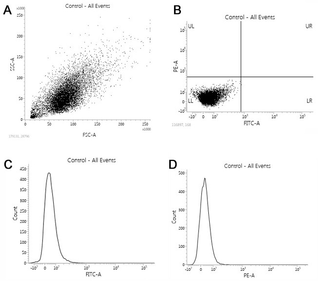
A and B. Discrimination of the cells based on two scatter parameters by flow cytometric gating strategy (dot plot). C and D. Cell counting based on the specified marker (log histogram).
Acknowledgments
Funding: This work was supported by the National Institutes of Health/National Institute on Drug Abuse 2R01-DA029121-01A1 and ARDF to Dr. Luca Cucullo.
Competing interests
The authors declare no competing interests.
Citation
Readers should cite both the Bio-protocol article and the original research article where this protocol was used.
References
- 1.Cossarizza A. and Salvioli S.(1998). Purdue Cytometry CD-ROM Series vol. 4. [Google Scholar]
- 2.Green D. R. and Reed J. C.(1998). Mitochondria and apoptosis. Science 281(5381): 1309-1312. [DOI] [PubMed] [Google Scholar]
- 3.Kaisar M. A., Sivandzade F., Bhalerao A. and Cucullo L.(2018). Conventional and electronic cigarettes dysregulate the expression of iron transporters and detoxifying enzymes at the brain vascular endothelium: In vivo evidence of a gender-specific cellular response to chronic cigarette smoke exposure. Neurosci Lett 682: 1-9. [DOI] [PMC free article] [PubMed] [Google Scholar]
- 4.Kaisar M. A., Villalba H., Prasad S., Liles T., Sifat A. E., Sajja R. K., Abbruscato T. J. and Cucullo L.(2017). Offsetting the impact of smoking and e-cigarette vaping on the cerebrovascular system and stroke injury: Is Metformin a viable countermeasure? Redox Biol 13: 353-362. [DOI] [PMC free article] [PubMed] [Google Scholar]
- 5.Logan A., Pell V. R., Shaffer K. J., Evans C., Stanley N. J., Robb E. L., Prime T. A., Chouchani E. T., Cocheme H. M., Fearnley I. M., Vidoni S., James A. M., Porteous C. M., Partridge L., Krieg T., Smith R. A. and Murphy M. P.(2016). Assessing the mitochondrial membrane potential in cells and in vivo using targeted click chemistry and mass spectrometry. Cell Metab 23(2): 379-385. [DOI] [PMC free article] [PubMed] [Google Scholar]
- 6.Perry S. W., Norman J. P., Barbieri J., Brown E. B. and Gelbard H. A.(2011). Mitochondrial membrane potential probes and the proton gradient: a practical usage guide. Biotechniques 50(2): 98-115. [DOI] [PMC free article] [PubMed] [Google Scholar]
- 7.Prasad S., Sajja R. K., Kaisar M. A., Park J. H., Villalba H., Liles T., Abbruscato T. and Cucullo L.(2017). Role of Nrf2 and protective effects of Metformin against tobacco smoke-induced cerebrovascular toxicity. Redox Biol 12: 58-69. [DOI] [PMC free article] [PubMed] [Google Scholar]
- 8.Smiley S. T., Reers M., Mottola-Hartshorn C., Lin M., Chen A., Smith T. W., Steele G. D. Jr.and Chen L. B.(1991). Intracellular heterogeneity in mitochondrial membrane potentials revealed by a J-aggregate-forming lipophilic cation JC-1. Proc Natl Acad Sci U S A 88(9): 3671-3675. [DOI] [PMC free article] [PubMed] [Google Scholar]
- 9.Suski J. M., Lebiedzinska M., Bonora M., Pinton P., Duszynski J. and Wieckowski M. R.(2012). Relation between mitochondrial membrane potential and ROS formation. Methods Mol Biol 810: 183-205. [DOI] [PubMed] [Google Scholar]
- 10.Zorova L. D., Popkov V. A., Plotnikov E. Y., Silachev D. N., Pevzner I. B., Jankauskas S. S., Babenko V. A., Zorov S. D., Balakireva A. V., Juhaszova M., Sollott S. J. and Zorov D. B.(2018). Mitochondrial membrane potential. Anal Biochem 552: 50-59. [DOI] [PMC free article] [PubMed] [Google Scholar]