Abstract
Semiconducting polymers are promising materials for photocatalysis, batteries, fuel applications, etc. One of the most useful photocatalysts is polymeric carbon nitride (PCN), which is usually produced during melamine condensation. In this work, a novel method of obtaining a PCN nanocomposite, in which PCN forms an amorphous layer coating on oxide nanoparticles, is presented. Microwave hydrothermal synthesis (MHS) was used to synthesize a homogeneous mixture of nanoparticles consisting of 80 wt.% AlOOH and 20 wt.% of ZrO2. The nanopowders were mechanically milled with melamine, and the mixture was annealed in the temperature range of 400–600 °C with rapid heating and cooling. The above procedure lowers PCN formation to 400 °C. The following nanocomposite properties were investigated: band gap, specific surface area, particle size, morphology, phase composition, chemical composition, and photocatalytic activity. The specific surface of the PCN nanocomposite was as high as 70 m2/g, and the optical band gap was 3 eV. High photocatalytic activity in phenol degradation was observed. The proposed simple method, as well as the low-cost preparation procedure, permits the exploitation of PCN as a polymer semiconductor photocatalytic material.
Keywords: microwave hydrothermal synthesis, AlOOH-ZrO2, nanocomposites, polymeric carbon nitride (PCN), band gap, photocatalysis, γ-Al2O3-ZrO2 nanopowders
1. Introduction
Photocatalysis is based on the photoabsorption by a semiconducting material at its surface. Photon absorption leads to the generation of electron–hole pairs, and the electron should reach the surface without hole–electron recombination. Therefore, considerable efforts have been made to enhance photocatalytic performance by effective charge separation. The major problems associated with a single organic component photocatalyst are as follows: (I) low specific surface area (SSABET) of the photocatalyst materials, which limits the interactions of the organic molecules with the photocatalyst surface, and (II) poor stability and reusability [1]. In recent years, binary or ternary photocatalysts have attracted considerable attention owing to their favorable advanced oxidation processes under stimulated light [2,3]. Over the last few decades, numerous approaches have been developed to enhance the photocatalytic efficiency of a photocatalyst, including doping with various chemical elements (Cr, Fe, B, S) [4,5,6,7], incorporating co-catalysts [8], including oxides [9], or the coupling of two or more semiconductors. Some of these have shown promising photocatalytic activities for the degradation of toxic pollutants under visible light irradiation because of their structural features and suitable band gaps in the range of 1.7–3 eV. However, the challenge is to find a semiconductor photocatalyst that is synthesized in an energy-efficient way, does not use critical raw materials, and does not require complicated post-synthesis modifications to tune the band gap.
Recently, the attention of scientists has been focused on manufacturing composites and heterojunctions involving C/N/H-containing solids, especially on synthesizing a material called graphitic carbon nitride (g-C3N4) [10], polymeric carbon nitride (PCN), or melon [11]. This compound is a product of melamine thermal condensation, possesses an optical band gap of 2.7 eV, and has great chemical stability [10]. The polymeric organic semiconductor PCN was reported mainly as a favorable photocatalyst in water splitting for hydrogen production [10]. Due to its properties, polymeric carbon nitride has also been used in the fields of photocatalysis, electrochemistry, and photo-electrochemistry [10,11].
Despite various advantages, PCN is characterized by low photocatalytic activity, which is caused by the rapid recombination of photo-generated electron–hole pairs [12,13,14,15], and a low specific surface area (SSABET). Thus, there is a need to improve its surface by various modifications and structural adjustments [16]. The introduction of a metal oxide (e.g., ZnO, TiO2, Al2O3, etc.) to PCN in order to form a heterostructured composite was found to be an effective method to enhance the long-term photostability and thermal stability [17]. However, the specific surface area of these composites is not high enough. PCN displays a SSABET of approximately, or even below, 10 m2/g [17]. To date, many complicated preparation methods have been developed to obtain PCN-based materials with larger SSABET. In principle, these methods can be classified into two categories. One category involves changing the morphology (e.g., porous nanostructure, hollow spheres, etc.) of PCN by template-assisted methods [17,18,19,20,21,22]. Another category is top-down chemical or thermal exfoliation of bulk PCN [17]. However, the abovementioned methods need additional post-treatment processes. Obviously, a simple, direct, and template-free strategy to synthesize PCN-based materials with large SSABET is desired.
The aim of our work was to utilize AlOOH (i.e., boehmite, aluminum oxyhydroxide) and ZrO2 nanoparticles in microwave hydrothermal synthesis as components of a PCN nanocomposite. The role of microwave hydrothermal synthesis in the obtaining of AlOOH-ZrO2 nanopowders during co-synthesis is described in our previous works [23,24,25]. Briefly, the process ensures a narrow size distribution, a high degree of crystallinity, and uniform intermixing of the two nanopowders in nanoscale [23,24,26,27,28,29]. The justification for the use of homogeneous AlOOH-ZrO2 nanopowders as a substrate for the deposition of PCN is to provide increased specific surface area (SSABET) and provide suitable thermal and mechanical stability. To the best of our knowledge, the role of homogeneous nanopowders of AlOOH-ZrO2 in PCN nanocomposite formation is investigated here for the first time. All the ingredients of the nanocomposite, AlOOH, ZrO2, and PCN are earth-abundant, which makes our PCN nanocomposite an ideal, inexpensive photocatalyst candidate.
2. Results
Nanocomposite Characterization
The starting homogeneous nanopowders of AlOOH-ZrO2 used in this work consisted of 80 wt.% of AlOOH and 20 wt.% of ZrO2 [23,24,25]. In order to mill it with melamine, 80 wt.% of the nanopowders and 20 wt.% of melamine were used. The mixture was annealed at 400, 450, 500, and 600 °C. The synthesized nanocomposites were cooled with reference to the annealing temperature for better clarity.
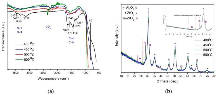
Figure 1a shows the FTIR spectra for the nanocomposites manufactured in the temperature range of 400–600 °C. In this experiment, polymeric carbon nitride was identified only in the nanocomposite prepared at 400 °C. It has been reported that the absorption band in the 1420–1620 cm−1 region is assigned to CN stretching and −NH2 bending vibrations in melamine [16]. The broad peak at 3100–3400 cm−1 can be attributed to the stretching vibration of N–H and O–H. The other peaks at 1257 and 1326 cm−1 are present due to the stretching vibration of aromatic C–N heterocycles consisting of trigonal N–C3 and C–NH–C bridging units [16], representing the formation of C–N–C bonds. The main indication of melon in a sample is the presence of a band around 800 cm−1, which belongs to triazine ring vibration in PCN [16]. It can be seen that the higher the annealing temperature of the nanocomposites, the weaker the intensity of the C–N bands.
Figure 1.
(a) FTIR spectra and (b) XRD spectra of the nanocomposites prepared in the temperature range 400–600 °C.
Figure 1b presents the X-ray powder diffraction (XRD) spectra of the nanocomposites annealed in the temperature range of 400–600 °C. Interestingly, XRD analysis does not show the presence of the AlOOH phase even in the nanocomposite annealed at 400 °C. The phase transition of AlOOH to γ-Al2O3 already took place [23]. Besides the γ-Al2O3 phase, all the samples contained ZrO2. In addition, the nanocomposite annealed at 450 °C contained traces of melamine condensation procucts. The lack of the PCN phase in the nanocomposite annealed at 400 °C may indicate an amorphous phase of this compound.
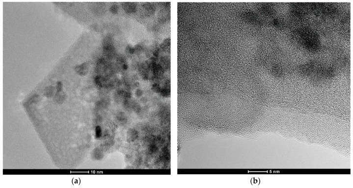
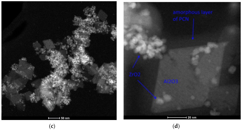
For the TEM examination, we chose only the composition that contains PCN (Figure 1a). Figure 2 shows the TEM images of the nanocomposite obtained at 400 °C. It is possible to distinguish three types of morphology: tetrahedral 30–50 nm flakes, which can be assigned to γ-Al2O3; spherical 3–5 nm ZrO2 particles; and 5–10 nm amorphous layers, which can be assigned to PCN (Figure 2b,d).
Figure 2.
(a,b) TEM images of the nanocomposite obtained at 400 °C; (c,d) STEM images of the nanocomposite obtained at 400 °C.
Table 1 presents the results of SSABET, helium density, and the average particle size of the nanocomposites obtained at various temperatures. There is a visible difference between SSABET for the nanocomposite annealed at 400 °C and for the nanocomposites obtained at higher temperatures.
Table 1.
Specific surface area, helium density, particle size, and pores dimensions of the investigated materials. The SSABET represents specific surface area, and BJH describes Barrett- Joyner-Halenda method.
| Sample Name | SSABET | Density (g/cm3) | Average Particle Size Calculated from SSABET (nm) | BJH Adsorption Average Pore Diameter (nm) | Total Pore Volume (cm3/g) |
|---|---|---|---|---|---|
| Multipoint (m2/g) | |||||
| Nanocomposite 400 °C | 79.5 | 3.75 ± 0.01 | 20 | 9.8 | 0.191 |
| Reference (Al2O3-ZrO2 annealed at 400 °C) | 108.6 | 3.51 ± 0.2 | 16 | 12.1 | 0.337 |
| Nanocomposite 450 °C | 132.9 | 3.56 ± 0.01 | 13 | 10.9 | 0.311 |
| Nanocomposite 500 °C | 120.0 | 3.71 ± 0.02 | 14 | - | - |
| Nanocomposite 600 °C | 92.4 | 3.76 ± 0.06 | 17 | 13.9 | 0.313 |
The reference sample γ-Al2O3-ZrO2 nanopowder annealed at 400 °C is characterized by a SSABET of 108 m2/g. The presence of a thin, nanometric PCN layer on the nanoparticle surface slightly reduces SSABET (nanocomposite 400 °C, Table 1). On the other hand, the SSABET value of above 100 m2/g for the nanocomposites annealed at 450 and 500 °C could be the result of the crystallization of some of the melamine condensation products, which decompose at higher temperatures. It is worth noting that the pure γ-Al2O3-ZrO2 obtained after annealing at 400 °C (reference for PCN nanocomposite 400 °C) had an evident influence on the SSABET of the PCN nanocomposite (Table 1). The deposition of the PCN layer on Al2O3-ZrO2 reduced slightly the SSABET from 108 to ~80 m2/g. This value of SSABET for the PCN nanocomposite is relatively high, because pure PCN is characterized by a SSABET of ~10 m2/g [26].
Interestingly, the density values of the nanocomposites annealed at 400, 500, and 600 °C are nearly the same. Only one sample (the nanocomposite annealed at 450 °C) has a slightly lower density (Table 1). In addition, all the prepared nanocomposites showed smaller densities than the reference sample with a density of 3.75 g/cm3 (Al2O3-ZrO2 annealed at 400 °C). This fact could be explained by the reduction of Zr4+ and Al3+ ions in the presence of melamine ok its decomposition products, obtaining metallic precipitations not visible during XRD examination. Thus, these ions could lead to the increased density of the PCN nanocomposites in comparison with the reference sample.
The relationship between SSABET and the density values for the homogenous nanomaterials was observed in our prior research [27,28]: the higher the SSABET, the smaller the density. Our PCN nanocomposites do not show the abovementioned trend (Table 1). In this case, the SSABET differs while the density remains approximately constant. We attribute that lack of significant change of the density to the applied annealing temperature, melamine condensation, and its interconversion processes. It means, for example, that for nanocomposites prepared at 450 °C, the nanoparticles and pores of Al2O3-ZrO2 are covered by a PCN layer (closed pores), which causes lower density (helium pycnometry). At higher temperatures, the PCN undergoes further interconversion and decomposition, which increases the SSABET while the density remains at the same value.
Table 1 also shows the average pore diameter and total pore volume for the investigated nanocomposites. There is no influence of porosity on the photocatalytic properties of the nanocomposites. Nanocomposite 400 °C has the smallest SSABET and porosity and shows the largest photocatalytic effect. He et al. [29], who investigated polyoxometalate (POMs)-functionalized g-C3N4, showed that, compared with C3N4, POMs-modified samples demonstrated slightly better efficiencies in photodegradation of phenol and Methylene blue (MB). It was suggested that the increased specific surface area, porous volume, and efficient charge transfer can influence photocatalysis [26].
In comparison to He et al. [26], our materials are characterized by higher specific surface areas and bigger pore volumes. Thus, we think that the active PCN layer on the surface of Al2O3-ZrO2 prepared at 400 °C has a greater effect on photocatalytic performance in our case than SSABET and the material’s pore volume.
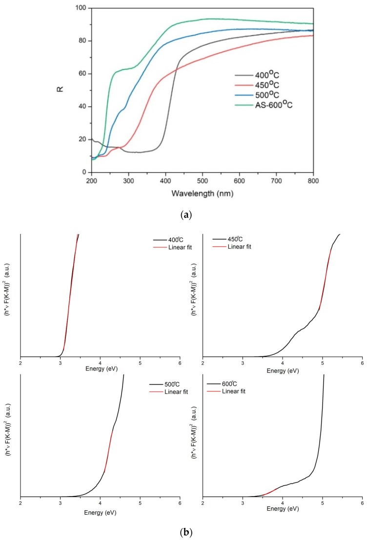
Figure 3a shows the total reflectance of the nanocomposites prepared in the temperature range of 400–500 °C. As-synthesized (AS) AlOOH-ZrO2 homogenous nanopowders after annealing at 600 °C, where AlOOH transformed completely into γ-Al2O3, were added as a reference.
Figure 3.
(a) Total reflectance of the nanocomposites prepared in the 400–500 °C temperature range. In addition, the AlOOH-ZrO2 nanopowders annealed at 600 °C were added as a reference (AS 600 °C, green line). (b) Reflectance UV–Vis spectra of Kubelka–Munk (K–M) functions vs energy (eV) for the investigated materials.
The reflectance of all the samples in the longer wavelength area of the spectrum is relatively high. In order to calculate the material band gap, we used the procedure described in [30,31]. Briefly, the reflectance was converted into a Kubelka–Munk function using Equation (1) [32,33]:
| (1) |
where F(R) is the Kubelka–Munk function and R is the sample reflectance.
Information about the band gap (Eg) can be obtained using the equation proposed by Tauc, Davis, and Mott, i.e., Equation (2) [34,35]:
| (2) |
where α is the absorption of the material, h is the Planck constant, ν the frequency of light, and Eg is the band gap. The exponent 1/n depends on the type of transition in the material, and for the cases of all the samples, we assumed a direct transition; thus, n = 2. Because F(R) is proportional to α [36], one can determine the band gap from the following formula:
| (3) |
The band gap can be determined from a plot of (F(R) hν)2 against hν by extrapolating the F(R) value to zero (Figure 3b). Table 2 shows the calculated band gap values for the investigated materials.
Table 2.
Band gap values calculated for the investigated nanocomposites.
| Sample Name | Band Gap (eV) |
|---|---|
| Nanocomposite 400 °C | 3.0 |
| Nanocomposite 450 °C | 3.5/4.7 |
| Nanocomposite 500 °C | 4.0/4.8 |
| AS 600 °C | 5.1–5.2 |
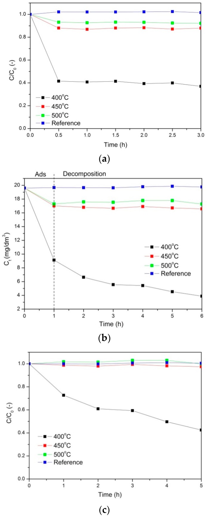
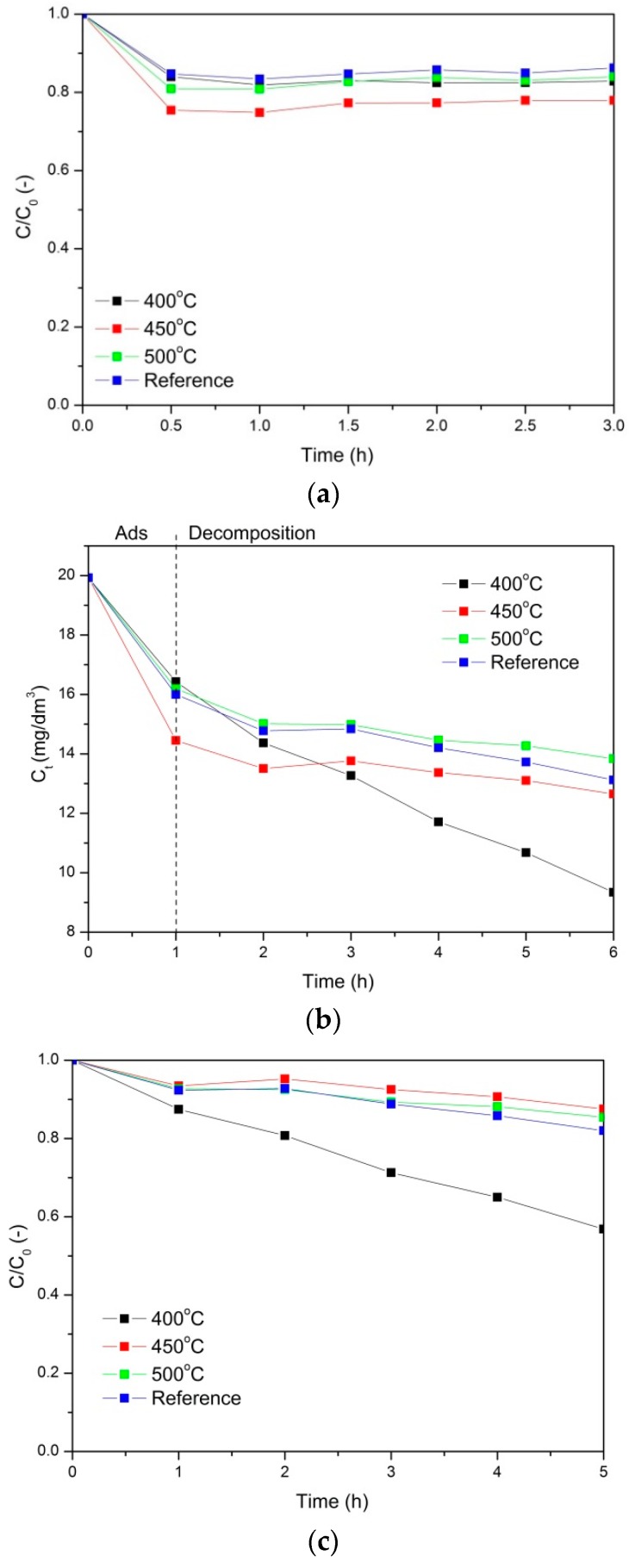
Photocatalytic properties of the nanocomposites prepared at 400, 450, and 500 °C are presented in Figure 4 and Figure 5. In addition, the photocatalytic tests were also performed for a reference sample: AlOOH-ZrO2 nanopowders annealed at 400 °C for 5 h (after annealing, the nanopowders consisted of γ-Al2O3 and ZrO2). Figure 4 and Figure 5 show phenol and Orange II adsorption and decomposition in the presence of the mentioned nanocomposites, respectively.
Figure 4.
Adsorption of phenol (a) Photocatalytic decomposition of phenol, where (b) presents the absolute change of the phenol concentration and (c) presents the relative change of the phenol concentration.
Figure 5.
Adsorption of Orange II (a) Photocatalytic decomposition of Orange II, where (b) presents the absolute change of the phenol concentration and (c) presents the relative change of the phenol concentration.
Based on the analysis of the obtained results, it was found that for all the tested photocatalysts, the adsorption process took 1 h before the actual photocatalytic oxidation process took place. Figure 4a, where the adsorption of phenol is presented, shows that the most efficient nanocomposite was the one annealed at 400 °C. The aforementioned PCN nanocomposite adsorbed 60% of the phenol from the solution. The adsorption on the reference sample was negligible, and on the nanocomposites annealed at 450 and 500 °C, approximately 10% of the phenol was adsorbed.
Next, the solution was irradiated with UV light. The results of the phenol photocatalytic decomposition are shown in Figure 4b. In Figure 4b, the absolute change of the phenol concentration is shown. The first step of the process (1 h) occurred in the dark and corresponded to adsorption. After 1 h, the UV light was turned on and the photocatalytic process was conducted. As a result, the most efficient material was the nanocomposite annealed at 400 °C. There was no phenol decomposition on the reference material and very little phenol decomposition on the nanocomposites annealed at 450 and 500 °C, which is also shown in Figure 4c in the change of the relative concentration of phenol. The final degree of phenol decomposition for the PCN nanocomposite annealed at 400 °C was approximately 58%.
Another model pollutant used in the experiments was Orange II. The relative changes of the Orange II concentration during adsorption in the dark are presented in Figure 5a. The adsorption occurred the most efficiently on the nanocomposites annealed at 450 °C, but it was only on the level of 25%. For the other materials, the adsorption was less efficient.
In Figure 5b, the photocatalytic decomposition of Orange II is presented. After 1 h of adsorption in the dark, UV light was applied, and the decomposition of the pollutant started. At first, the decomposition was more efficient on the nanocomposites annealed at 450 °C, but after 3 h, the PCN nanocomposite annealed at 400 °C was the most effective, reaching (after 5 h) 43% Orange II decomposition.
3. Discussion
The results show that the most promising material for photocatalytic applications is γ-Al2O3-ZrO2 covered by a PCN layer (Figure 6) obtained at 400 °C. The temperature of 400 °C is unexpected for PCN formation, because melamine, according to the literature [37], undergoes a transition to PCN above 600 °C. In order to synthesize PCN, the annealing of melamine has to be precisely stopped at the right time and at a given temperature. According to [37], the decomposition of melamine takes place through dimer (melam) and then trimer (melem) formation at a temperature below 400 °C. Melem exists in the temperature range of 400–500 °C. Above 600 °C, melem starts to polymerize to PCN (melon) [37]. In our case, the formation of PCN took place at a ~200 °C lower temperature than reported in the literature. In our opinion, this is due to the presence of nano-sized metal oxide in the nanocomposite and a fast heating rate (50 °C/min). For comparison, the pure melamine decomposition temperature tested in our laboratory is the same as that reported in the literature [37], ~600 °C. The presence of uniform, co-synthesized AlOOH-ZrO2 nanopowder shifts the formation of PCN by 200 °C towards lower temperatures.
Figure 6.
Scheme of AlOOH, ZrO2, and melamine leading to the formation of the polymeric carbon nitride (PCN) nanocomposite. The circles represent ZrO2, the pentagons represent AlOOH/Al2O3, and the blue triangles represent melamine powder.
The very fast heating (50 °C/min) and long dwelling time at 400 °C (5h) applied in our synthesis process allows the covering of boehmite particles by an amorphous layer of PCN and allows AlOOH particles to transform into γ-Al2O3 without destroying the PCN layer (Figure 2d). We think that such phase transformation was possible without destroying the PCN layer, because it was a very slow process, which took place within the same crystal structure with cubic symmetry.
Covering γ-Al2O3 and ZrO2 nanoparticles with an amorphous layer of PCN in the nanocomposite annealed at 400 °C can be also confirmed by the SSABET results. Table 1 shows that the specific surface area of the PCN nanocomposite (400 °C) is slightly lower than that of the γ-Al2O3-ZrO2 nanopowder but much smaller than the SSABET of the nanocomposites prepared in the temperature range of 450–500 °C. This can be explained by the covering of the surface of the nanoparticles with a thin organic layer and the fact that some PCN was formed in the gaps between particles.
Another confirmation of the PCN layer formation is the band gap value, 3 eV, which was significantly lower than the reference material (pure γ-Al2O3-ZrO2 nanopowders annealed at 600 °C), characterized by 5.1 and 5.2 eV band gaps. The layer presumably screens the nanoparticles from interaction with light, and they do not contribute to the overall band gap. On the other hand, pure PCN has a moderate bandgap of 2.7 eV, corresponding to an optical wavelength of 460 nm [14]. Considering the thermodynamic losses and other potentials in the photocatalytic process, the band gap of 2.7 eV can be found in between 2 eV and 3.1 eV [14].
Polymeric carbon nitride materials have been investigated recently in various fields of photocatalysis [1,3,6,7]. Carbon nitrides have applications as sanitizers for the removal of contaminants, including pollutants and pathogenic microorganisms from drinking water and air [35]. There are also studies [1,26,38,39,40,41] in which PCN has been successfully used in the degradation of soluble dyes, such as methyl orange (MO), methylene blue (MB), phenol, rhodamine B, and crystal violet (CV).
Vattikuti et al. [1] showed that MoS2/Al2O3/g-C3N4 nanocomposite has good photocatalytic performance for the degradation of CV dye under visible light irradiation. They reported [1] that the photodegradation rate of CV increased with the increasing Al2O3 and MoS2 content up to 20% in comparison with pure g-C3N4. The photocatalytic activity of this nanocomposite was approximately 10.28 higher than that of pure g-C3N4. On the other hand, He et al. [26] found that pure PCN was not as effective in phenol decomposition as a POMs-modified sample, where the concentration of phenol decreased up to ~0.5 over 3 h. This result was worse than that in our case where the PCN nanocomposite annealed at 400 °C showed a decrease of phenol concentration to 0.5 over 30 min (Figure 4c). However, our outcomes are in contrast to the results described by Ren et al. [40], who investigated the photocatalytic properties of Ag2O/g-C3N4 composites. They demonstrated high photocatalytic activity for phenol degradation [40]. They [40] showed that in Ag2O/g-C3N4 composites under UV- and visible-light irradiation, phenol completely degraded in 20 and 90 min, respectively. The improved photocatalytic activities were attributed to the formation of a heterostructure between Ag2O and g-C3N4, the strong visible-light absorption, and the high separation efficiency of photoinduced electron—hole pairs resulting from the highly dispersed Ag2O particles [40].
In general, our findings regarding the photocatalytic activity of PCN nanocomposite are in agreement with others [7,26,29,38,39,41]. We think that photocatalytic efficiency depends more on the type of composite with PCN, then its specific surface area or porous volume structure. The photocatalytic properties of the PCN nanocomposites presented in this manuscript were investigated for the first time. Thus, it is difficult to compare our results with others. In summary, the addition of PCN nanocomposites to the presence of organic dyes and pollutants leads to relatively fast degradation of the contaminants.
4. Materials and Methods
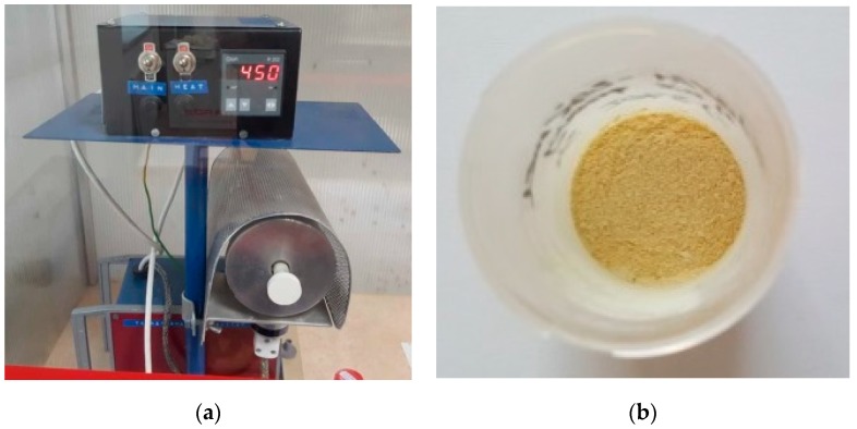
The procedure for synthesizing nanopowders containing AlOOH with ZrO2 addition is described in detail elsewhere [23,24,25]. The reagents used in the process were zirconyl chloride octahydrate (ZrOCl2·8H2O, Sigma-Aldrich, St. Louis, MI, USA (99.5%)), sodium hydroxide (NaOH, analytically pure, Chempur, Piekary Sląskie, Poland), and aluminum nitrate nonahydrate (Al(NO3)3·9H2O, analytically pure, Chempur, Piekary Sląskie, Poland). The microwave reactions took place in a microwave reactor (2.45 GHz, 600 W, MAGNUM II ERTEC, Wrocław, Poland). As-prepared AlOOH-ZrO2 nanopowder was hand mixed in a zirconia mortar with 20 wt.% of melamine (Sigma-Aldrich, CAS Number 108-78-1 (99%)). In the next step, the prepared powder was annealed in a tube furnace (homemade, Model 1, IHPP PAS, Warsaw, Poland) in 4 different temperatures (in the range of 400–600 °C) for 5 h in air (Figure 7). In all cases, the constant heating rate of 50 °C/min was applied.
Figure 7.
(a) Homemade tube furnace used for nanocomposites synthesis; (b) PCN nanocomposite obtained at 400 °C.
All the powders after synthesis were exanimated using a Fourier transform infrared (FTIR) spectrometer (Bruker Optics, Tensor 27, Bruker BioSpin GmbH, Rheinstetten, Germany) equipped with a diamond attenuated total reflectance (ATR) accessory. The ATR-FTIR spectra were recorded at room temperature in the 4000–400 cm−1 range. The spectral resolution and accuracy of the measurements were 4 cm−1 and 1 cm−1, respectively.
X-ray diffraction (XRD) patterns of the nanopowders were collected on a diffractometer (X’Pert PRO, PANalytical, Almelo, Netherlands) equipped with a copper anode (Cu K 1) and an ultra-fast PIXcel1D detector. The analysis was performed at room temperature in the 2θ range of 10–80° with a step size of 0.03°.
The microstructures of the nanopowders and nanocomposites were investigated using conventional high-resolution (HR) transmission electron microscopy (TEM) and scanning (STEM) techniques with a FEI TECNAI G2 F20 S-TWIN electron microscope (Thermo Fisher Scientific, Waltham, MA, USA).
Helium density measurements were carried out using a helium pycnometer (AccuPyc II 1340, FoamPyc V1.06, Micromeritics, Norcross, GA, USA). The measurements were carried out in accordance with the ISO 12154:2014 standard at 25 °C.
The specific surface area of the nanopowders was determined using a surface analyzer (Gemini 262 2360, V 2.01, Micromeritics, Norcross, GA, USA). The nitrogen adsorption method was applied based on the linear 263 form of the Brunauer–Emmett–Teller (BET) isotherm equation. The obtained data were analyzed using the MicroActive software V4.03 (Interactive Data Analysis Software, Micromeritics). The detailed experimental procedure and the determination of particle size using the SSABET method is described elsewhere [42]. Based on the results of the specific surface area and density, the average particle size was calculated with the assumption that all the particles were spherical and identical.
The band gap experiments were conducted for nanocomposites formed into pellets. The UV–Vis reflectance of samples was measured at room temperature using Lambda 650 (Perkin-Elmer, Waltham, MA, USA) equipped with an integrating sphere module. Spectralon SRS-99-01030 reflectance material was used as a reference sample. The total reflectance of the samples was collected.
The photocatalytic activity of the obtained nanomaterials was determined on the basis of water pollutant degradation tests under the influence of UV–Vis radiation with high UV intensity (6 lamps, 20 W each, 40 cm long, type: ISOLDE, Koninklijke Philips N.V., Amsterdam, Netherlands). The lamp used in the experiments was not monochromatic. The wavelength range was from 200–800 nm. Phenol (neutral) and Orange II dye (anionic dye) were used as the model pollutants. In a 150 cm3 glass beaker, 20 mg of the appropriate photocatalyst (nanocomposite) was suspended and then 100 cm3 of the dye or phenol solution with an initial concentration of 20 mg/dm3 was added. The final concentration of the catalyst in the mixture was 0,02 g/dm3. The suspension was stirred continuously using a magnetic stirrer (500 rpm). Further, suspensions were irradiated with ultraviolet light for 5 h. The pollutant degradation process consisted of 2 stages. The first stage was an adsorption in a darkroom conducted until the equilibrium between the liquid and solid was established. The optimal time for adsorption was determined individually for each compound. Samples were taken at identical time intervals (every hour) and tested on a UV–Vis spectrophotometer. The concentrations of the individual samples were determined on the basis of calibration curve equations drafted for the given pollutants.
5. Conclusions
In this work a PCN-γ-Al2O3-ZrO2 nanocomposite was obtained for the first time.
The synthesis of the PCN-based nanocomposite photocatalyst consisted of two steps: (a) microwave hydrothermal synthesis of AlOOH-ZrO2 nanopowders and (b) controlled addition of melamine to AlOOH-ZrO2 nanopowders and subsequent thermal treatment to obtain PCN-nanocomposites. This synthesis approach to PCN-nanocomposites is unique and produces PCN nanocomposite photocatalysts, which are highly in demand, in an easy, clean, energy-efficient, and low-cost way.
It was shown that PCN was formed at the surface of γ-Al2O3 and ZrO2 at 400 °C by means of a melamine thermal condensation process, which took place at a ~200 °C lower temperature than the state of the art. We postulate that this was possibly due to the interaction of the melamine with the γ-Al2O3 and ZrO2 nanoparticles, which provide high specific surface areas and morphology favorable for the formation of a PCN layer.
It was observed that AlOOH fully transformed into γ-Al2O3 without affecting the PCN layer structure.
The PCN nanocomposite has a 3 eV band gap and shows significant photocatalytic ability for common pollutant adsorption and degradation. The proposed simple and low-cost preparation method permits the exploitation of PCN as a polymer semiconductor photocatalytic material.
Acknowledgments
The authors are indebted to Jan Mizeracki for help with the materials’ preparation.
Author Contributions
Conceptualization, I.K.; Funding acquisition, I.K. and W.L.; Investigation, I.K., J.W., P.N., J.S.-K., S.S., A.B., A.M., and W.L.; Methodology, I.K.; Supervision, I.K.; and Original draft preparation, I.K. This publication is part of I.K.’s habilitation thesis.
Funding
This research was funded by the Polish National Science Centre grant number: UMO-2013/11/D/ST8/03429- “Sonata 6”. The research subject was partly carried out with the use of equipment funded by the project CePT, reference: POIG.02.02.00-14-024/08, financed by the European Regional Development Fund within the Operational Programme “Innovative Economy” for 2007–2013.
Conflicts of Interest
The authors declare no conflicts of interest.
Footnotes
Sample Availability: Samples of the all compounds described in this work are available from I.K.
References
- 1.Vattikuti S.V.P., Byon C. Hydrothermally synthesized ternary heterostructured MoS2/Al2O3/g-C3N4 photocatalyst. Mater. Res. Bull. 2017;96:233–245. doi: 10.1016/j.materresbull.2017.03.008. [DOI] [Google Scholar]
- 2.Chen J., Garcia E.D., Oliviero E., Oliviero L., Maugé F. Effect of high pressure sulfidation on the morphology and reactivity of MoS2 slabs on MoS2/Al2O3 catalyst prepared with citric acid. J. Catal. 2016;339:153–162. doi: 10.1016/j.jcat.2016.04.010. [DOI] [Google Scholar]
- 3.Reddy P.A.K., Reddy P.V.L., Kwon E., Kim K., Akter T., Kalagara S. Recent advances in photocatalytic treatment of pollutants in aqueous media. Environ. Int. 2016;91:94–103. doi: 10.1016/j.envint.2016.02.012. [DOI] [PubMed] [Google Scholar]
- 4.Li H., Yin S., Wang Y., Sekino T., Lee S.W., Sato T. Roles of Cr3+ doping and oxygen vacancies in SrTiO3 photocatalysts with high visible light activity for NO removal. J. Catal. 2013;297:65–69. doi: 10.1016/j.jcat.2012.09.019. [DOI] [Google Scholar]
- 5.Aman N., Das N.N., Mishra T. Effect of N-doping on visible light activity of TiO2–SiO2 mixed oxide photocatalysts. J. Environ. Chem. Eng. 2016;4:191–196. doi: 10.1016/j.jece.2015.10.037. [DOI] [Google Scholar]
- 6.Yu W., Zhang J., Peng T. New insight into the enhanced photocatalytic activity of N-, C- and S-doped ZnO photocatalysts. Appl. Catal. B Environ. 2016;181:220–227. doi: 10.1016/j.apcatb.2015.07.031. [DOI] [Google Scholar]
- 7.Ge L., Han C., Xiao X., Guo L., Li Y. Enhanced visible light photocatalytic hydrogen evolution of sulfur-doped polymeric g-C3N4 photocatalysts. Mater. Res. Bull. 2013;48:3919–3925. doi: 10.1016/j.materresbull.2013.06.002. [DOI] [Google Scholar]
- 8.Song Y., Wei S., Rong Y., Lu C., Chen Y., Wang J., Zhang Z. Enhanced visible light photocatalytic hydrogen evolution activity of Er3+:Y3Al5O12/PdSeZnS by conduction band co-catalysts (MoO2, MoS2 and MoSe2) Int. J. Hydrogen Energy. 2016;41:12826–12835. doi: 10.1016/j.ijhydene.2016.06.065. [DOI] [Google Scholar]
- 9.Jin C., Liu G., Zu L., Qin Y., Yang J. Preparation of Ag@Ag3PO4@ZnO ternary heterostructures for photocatalytic studies. J. Colloid Interface Sci. 2015;453:36–41. doi: 10.1016/j.jcis.2015.03.066. [DOI] [PubMed] [Google Scholar]
- 10.Wang X., Maeda K., Thomas A., Takanabe K., Xin G., Carlsson J.M., Domen K., Antonietti M. A metal-free polymeric photocatalyst for hydrogen production from water under visible light. Nat. Mater. 2009;8:76–80. doi: 10.1038/nmat2317. [DOI] [PubMed] [Google Scholar]
- 11.Kessler F.K., Zheng Y., Schwarz D., Merschjann C., Schnick W., Wang X., Bojdys M.J. Functional carbon nitride materials design strategies for electrochemical Devices. Nat. Rev. Mater. 2017;2:1–17. doi: 10.1038/natrevmats.2017.30. [DOI] [Google Scholar]
- 12.Duan J., Chen S., Jaroniec M., Qiao S. Porous C3N4 nanolayers@N-graphene films as catalyst electrodes for highly efficient hydrogen evolution. ACS Nano. 2015;9:931–940. doi: 10.1021/nn506701x. [DOI] [PubMed] [Google Scholar]
- 13.Ye S., Wang R., Wu M.Z., Yuan Y.P. A review on g-C3N4 for photocatalytic water splitting and CO2 reduction. Appl. Surf. Sci. 2015;358:15–27. doi: 10.1016/j.apsusc.2015.08.173. [DOI] [Google Scholar]
- 14.Wen J., Xie J., Chen X., Li X. A review on g-C3N4-based photocatalysts. Appl. Surf. Sci. 2017;391:72–123. doi: 10.1016/j.apsusc.2016.07.030. [DOI] [Google Scholar]
- 15.Ma T., Dai S., Jaroniec M., Qiao S. Graphitic carbon nitride nanosheet-carbon nanotube three-dimensional porous composites as high-performance oxygen evolution electrocatalysts. Angew. Chem. Int. Ed. 2014;53:7281–7285. doi: 10.1002/anie.201403946. [DOI] [PubMed] [Google Scholar]
- 16.Wang X., Liu C., Li X.-L., Li F.-T., Li Y.-P., Zhao J., Liu R.-H. Construction of g-C3N4/Al2O3 hybrids via in-situ acidification and exfoliation with enhanced photocatalytic activity. Appl. Surf. Sci. 2017;394:340–350. doi: 10.1016/j.apsusc.2016.10.081. [DOI] [Google Scholar]
- 17.Feng D., Cheng Y., He J., Zheng L., Shao D., Wang W., Wang W., Lu F., Dong H., Liu H., et al. Enhanced photocatalytic activities of g-C3N4 with large specific surface area via a facile one-step synthesis process. Carbon. 2017;125:454–463. doi: 10.1016/j.carbon.2017.09.084. [DOI] [Google Scholar]
- 18.Li S., Wang Z., Wang X., Sun F., Gao K., Hao N. Orientation controlled preparation of nanoporous carbon nitride fibers and related composite for gas sensing under ambient conditions. Nano Res. 2017;10:1710–1719. doi: 10.1007/s12274-017-1423-8. [DOI] [Google Scholar]
- 19.Sun J., Zhang J., Zhang M., Antonietti M., Fu X., Wang X. Bioinspired hollow semiconductor nanospheres as photosynthetic nanoparticles. Nat. Commun. 2012;3:1139–1145. doi: 10.1038/ncomms2152. [DOI] [Google Scholar]
- 20.Li X., Zhang J., Chen X., Fischer A., Thomas A., Antonietti M. Condensed graphitic carbon nitride nanorods by nanoconfinement: Promotion of crystallinity on photocatalytic conversion. Chem. Mater. 2011;23:4344–4348. doi: 10.1021/cm201688v. [DOI] [Google Scholar]
- 21.Li X., Wang X., Antonietti M. Mesoporous g-C3N4 nanorods as multifunctional supports of ultrafine metal nanoparticles: Hydrogen generation from water and reduction of nitrophenol with tandem catalysis in one step. Chem. Sci. 2012;3:2170–2174. doi: 10.1039/c2sc20289a. [DOI] [Google Scholar]
- 22.Hu M., Reboul J., Furukawa S., Radhakrishnan L., Zhang Y., Srinivasu P., Iwai H., Wang H., Nemoto Y., Suzuki N., et al. Direct synthesis of nanoporous carbon nitride fibers using Al-based porous coordination polymers (Al-PCPs) Chem. Commun. 2011;47:8124–8126. doi: 10.1039/c1cc12378e. [DOI] [PubMed] [Google Scholar]
- 23.Koltsov I., Smalc-Koziorowska J., Przesniak-Welenc M., Małysa M., Kimmel G., McGlynn J., Ganin A., Stelmakh S. Mechanism of Reduced Sintering Temperature of Al2O3–ZrO2 Nanocomposites Obtained by Microwave Hydrothermal Synthesis. Materials. 2018;11:829. doi: 10.3390/ma11050829. [DOI] [PMC free article] [PubMed] [Google Scholar]
- 24.Malka I.E., Danelska A., Kimmel G. The Influence of Al2O3 Content on ZrO2-Al2O3 Nanocomposite Formation—The Comparison between Sol-Gel and Microwave Hydrothermal Methods. Mater. Today Proc. 2016;3:2713–2724. doi: 10.1016/j.matpr.2016.06.018. [DOI] [Google Scholar]
- 25.Koltsov I., Przesniak-Welenc M., Wojnarowicz J., Rogowska A., Mizeracki J., Malysa M., Kimmel G. Thermal and physical properties of ZrO2–AlO(OH) nanopowders synthesised by microwave hydrothermal method. J. Therm. Anal. Calorim. 2017;131:2273–2284. doi: 10.1007/s10973-017-6780-8. [DOI] [Google Scholar]
- 26.He J., Sun H., Indrawirawan S., Duan X., Tade M.O., Wang S. Novel polyoxometalate@g-C3N4 hybrid photocatalysts for degradation of dyes and phenolics. J. Coloid Interf. Sci. 2015;456:15–21. doi: 10.1016/j.jcis.2015.06.003. [DOI] [PubMed] [Google Scholar]
- 27.Opalinska A., Malka I., Dzwolak W., Chudoba T., Presz A., Lojkowski W. Size-dependent density of zirconia nanoparticles. Beilstein J. Nanotechnol. 2015;6:27–35. doi: 10.3762/bjnano.6.4. [DOI] [PMC free article] [PubMed] [Google Scholar]
- 28.Wojnarowicz J., Chudoba T., Koltsov I., Gierlotka S., Dworakowska S., Lojkowski W. Size control mechanism of ZnO nanoparticles obtained inmicrowave solvothermal synthesis. Nanotechnology. 2018;29:065601. doi: 10.1088/1361-6528/aaa0ef. [DOI] [PubMed] [Google Scholar]
- 29.Sano T., Tsutsui S., Koike K., Hirakawa T., Teramoto Y., Negishi N., Takeuchi K. Activation of graphitic carbon nitride (g-C3N4) by alkaline hydrothermal treatment for photocatalytic NO oxidation in gas phase. J. Mater. Chem. A. 2013;1:6489. doi: 10.1039/c3ta10472a. [DOI] [Google Scholar]
- 30.Nowak M., Kauch B., Szperlich P. Determination of energy band gap of nanocrystalline SbSI using diffuse reflectance spectroscopy. Rev. Sci. Instrum. 2009;80:046107. doi: 10.1063/1.3103603. [DOI] [PubMed] [Google Scholar]
- 31.Köferstein R., Jäger L., Ebbinghaus S.G. Magnetic and optical investigations on LaFeO3 powders with different particle sizes and corresponding ceramics. Solid State Ionics. 2013;249–250:1–5. doi: 10.1016/j.ssi.2013.07.001. [DOI] [Google Scholar]
- 32.Kubelka P., Munk F. Ein Beitrag zur Optik der Farbanstriche. Zeitschrift für Technische Physik. 1931;12:593–601. [Google Scholar]
- 33.Philips-Invernizzi B., Dupont D., Caze C. Bibliographical review for reflectance of diffusing media. Opt. Eng. 2001;40:1082–1093. doi: 10.1117/1.1370387. [DOI] [Google Scholar]
- 34.Tauc J., Grigorovici R., Vancu A. Optical Properties and Electronic Structure of Amorphous Germanium. Phys. Status Solidi B. 1966;15:627–637. doi: 10.1002/pssb.19660150224. [DOI] [Google Scholar]
- 35.Davis E.A., Mott N.F. Conduction in non-crystalline systems V. Conductivity, optical absorption and photoconductivity in amorphous semiconductors. Philos. Mag. 1970;22:0903–0922. doi: 10.1080/14786437008221061. [DOI] [Google Scholar]
- 36.Kortüm G., Vogel J. Die Theorie der diffusen Reflexion von Licht an pulverförmigen Stoffen. Z. Phys. Chem. 1958;18:110–122. doi: 10.1524/zpch.1958.18.1_2.110. [DOI] [Google Scholar]
- 37.Praus P., Svoboda L., Ritz M., Troppová I., Šihor M., Kočía K. Graphitic carbon nitride: Synthesis, characterization and photocatalytic decomposition of nitrous oxide. Mater. Chem. Phys. 2017;193:438–446. doi: 10.1016/j.matchemphys.2017.03.008. [DOI] [Google Scholar]
- 38.Cui Y., Ding Z., Liu P., Antonietti M., Fu X., Wang X. Metal-free activation of H2O2 by g-C3N4 under visible light irradiation for the degradation of organic pollutants. Phys. Chem. Chem. Phys. 2012;14:1455–1462. doi: 10.1039/C1CP22820J. [DOI] [PubMed] [Google Scholar]
- 39.Zhang M., Jiang W., Liu D., Wang J., Liu Y., Zhu Y., Zhu Y. Photodegradation of phenol via C3N4-agar hybrid hydrogel 3Dphotocatalysts with free separation. Appl. Catal. B Environm. 2016;183:263–268. doi: 10.1016/j.apcatb.2015.10.049. [DOI] [Google Scholar]
- 40.Ren H.-T., Jia S.-Y., Wu Y., Wu S.-H., Zhang T.-H., Han X. Improved Photochemical Reactivities of Ag2O/g-C3N4 in Phenol Degradation under UV and Visible Light. Ind. Eng. Chem. Res. 2014;53:17645–17653. doi: 10.1021/ie503312x. [DOI] [Google Scholar]
- 41.Shi L., Zhao K., Liu S. Photocatalytic degradation of MO and phenol over novel β-CoOOH/g-C3N4 composite under visible light irradiation. Mater. Lett. 2018;228:121–124. doi: 10.1016/j.matlet.2018.05.134. [DOI] [Google Scholar]
- 42.Wojnarowicz J., Opalinska A., Chudoba T., Gierlotka S., Mukhovskyi R., Pietrzykowska E., Sobczak K., Lojkowski W. Effect of water content in ethylene glycol solvent on the size of ZnO nanoparticles prepared using microwave solvothermal synthesis. J. Nanomater. 2016;2016:2789871. doi: 10.1155/2016/2789871. [DOI] [Google Scholar]


