

Abstract
The electroencephalogram (EEG) is a widely used non-invasive method for monitoring the brain. It is based upon placing conductive electrodes on the scalp which measure the small electrical potentials that arise outside of the head due to neuronal action within the brain. Historically this has been a large and bulky technology, restricted to the monitoring of subjects in a lab or clinic while they are stationary. Over the last decade much research effort has been put into the creation of “wearable EEG” which overcomes these limitations and allows the long term non-invasive recording of brain signals while people are out of the lab and moving about. This paper reviews the recent progress in this field, with particular emphasis on the electrodes used to make connections to the head and the physical EEG hardware. The emergence of conformal “tattoo” type EEG electrodes is highlighted as a key next step for giving very small and socially discrete units. In addition, new recommendations for the performance validation of novel electrode technologies are given, with standards in this area seen as the current main bottleneck to the wider take up of wearable EEG. The paper concludes by considering the next steps in the creation of next generation wearable EEG units, showing that a wide range of research avenues are present.
Keywords: Electroencephalography, Electrodes, Wearable
Introduction
The electroencephalogram (EEG) is a widely used non-invasive method for monitoring the brain. It is based upon placing conductive electrodes on the scalp which measure the small electrical potentials that arise outside of the head due to neuronal action within the brain. Its key benefits compared to other brain imaging techniques are that it has a very high time resolution—able to track events within the brain with millisecond accuracy—and that it is in principle portable allowing real-world neuroimaging to be performed outside of clinical and lab environments. As a result it is a very widely used sensing modality for a range of health and wellbeing applications and Brain–Computer Interfaces (BCI) ranging from epilepsy diagnosis [1] in healthcare to emotional monitoring [2] in BCIs.
Figure 1 shows the conventional set up that first comes to mind when discussing the EEG: a user who wears a head cap with holes to hold a number electrodes next to the scalp, and each electrode having a long wire to connect it to recording instrumentation. Nearly a decade ago collaborators and I introduced the concept of wearable EEG as “the evolution of ambulatory EEG units from the bulky, limited lifetime devices available today to small devices present only on the head that can record EEG for days, weeks, or months at a time” [3]. This would remove the wires, make units much more portable and long lasting, and enable a wide range of out of the lab EEG experiments in motion rich environments for both clinical and non-clinical uses that were never previously possible. Similar motivations from other groups for the creation of wearable EEG have been given in [4–6].
Fig. 1.
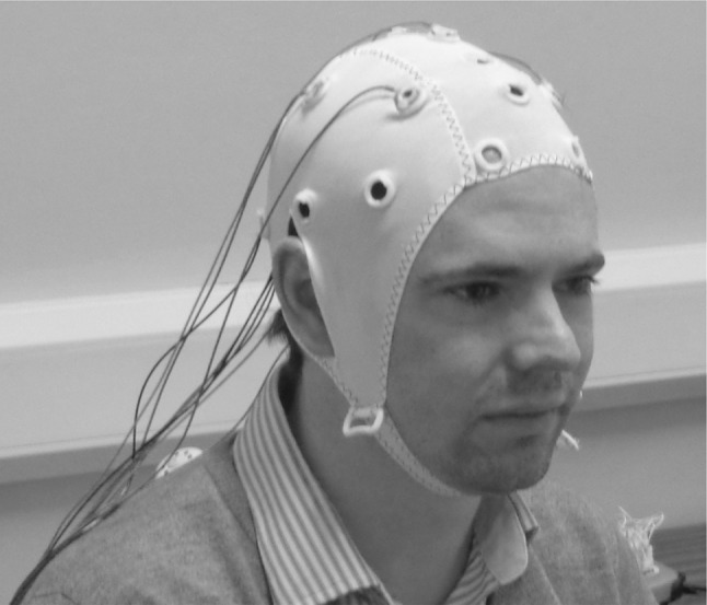
A conventional lab based EEG set up with metal electrodes on the scalp held in place by a cap with wires to connect to a recording instrumentation box
A huge amount of progress has now been made towards realising this aim, and this article will review the state of the art in wearable EEG as it exists today in late 2018, highlighting the bottlenecks which are still present and motivating future directions. The focus of this will be on EEG hardware—the electronics and the electrodes—rather than the many different uses and applications of wearable EEG technology. The most common uses of EEG remain in epilepsy diagnosis [1], sleep disorder diagnosis [7], and in Brain–Computer Interfaces [8], and a detailed review of each of these areas is beyond the scope of what is aimed for here. (Although a few more novel uses of EEG technology will be discussed when we come to consider where next in Sect. 6.) We will also assume a basic familiarity with the process of EEG sensing, the instrumentation required, and the typical waveforms produced. If required, excellent texts are available elsewhere covering the background of the EEG [9, 10] and the typical signal processing stages applied to extract information from the collected signals [11]. Recent systematic reviews on electrode materials [12], electrode types [13, 14], and amplifier topologies [15] are also available. The aim here is not to replicate these. Rather, it is to complement them with an overview of wearable EEG as a whole, with a particular focus on practical lessons learned.
In this paper, Sect. 2 overviews the state of the art in wearable EEG today, giving examples of what is currently available. Section 3 then overviews the electrodes which are used to make contact with the scalp, which is extended in Sect. 4 with details on the performance validation required to demonstrate that new electrodes meet (or exceed) the performance provided by current electrodes. This is very difficult to do, and is now seen as the main bottleneck to the wider take up of wearable EEG. Section 5 focuses on the EEG hardware, and particularly the emergence of flexible conformal tattoo electronics which, while only suitable for hair-free parts of the head, potentially offer significant advantages in terms of longevity and discreteness. Finally in Sect. 6, next steps are considered with there being a wide range of possibilities available which will define the next decade of research in wearable and beyond wearable EEG. The field of wearable EEG is far from done yet!
Wearable EEG today
One of the key features of wearable EEG is that recording units are present only on the head, compared to previous ambulatory units which commonly required an instrumentation box to be worn on a belt near the waist with long wires to connect to the electrodes [3]. This removal of long wires is critical for improving data quality and moving towards the mobile use of EEG units. Wires get tangled, making them difficult to set up, and unshielded EEG wires pick up very large amounts of interference during motion. This occurs due to direct 50/60 Hz mains induction, and due to the movement of the wires through the electro-magnetic fields present in the ambient environment (from the mains or elsewhere) with this movement of a conductor in a magnetic field also inducing a current [16]. As EEG amplifiers have a high input impedance small amounts of injected current can lead to large interference voltages, and these have complicated waveform patterns which reflect the motion of the cables and are difficult to predict. Reducing the length of the cables is the simplest way of reducing these artefacts and leads to a substantial increase in data quality.
Doing this requires all of the instrumentation electronics, and a wireless transmitter, to be small enough to be placed in a box which can be mounted on the head, and power efficient enough to be powered by a miniature battery which can also fit inside this box. Wireless data transmission is very power intensive [17] and historically real-time data compression has been required [18], together with lots of research into lower power instrumentation electronics [15] (especially for high channel count systems). Today, these purely electronic challenges have been overcome and a range of head worn EEG units are available from different manufacturers, at the cost of relatively limited battery lives. The 2018 state of the art from a number of commercial manufacturers is summarised in Table 1. Evaluations of signal quality and usability of such units are given in [19, 20].
Table 1.
Examples of state-of-the-art commercially available EEG units which are wearable and present only on the head
| EEG manufacturer and unit | mBrainTrain Smarting [21] | Brain Products LiveAmp [22] | g.tec g.Nautilus [23] | Cognionics Mobile-128 [24] | Emotiv Epoc Flex [25] |
|---|---|---|---|---|---|
| Channels | 24 | 32 | 32 | 128 | 32 |
| Sampling frequency/Hz | Up to 500 | Up to 1000 | Up to 500 | Up to 1000 | 128 |
| Resolution/bits | 24 | 24 | 24 | 24 | 14 |
| Size/mm | – | – | – | ||
| Weight/g | 60 | 60 | – | 460 | – |
| Battery life/h | 5 | 3 | 8 | 6 | 9 |
For manufacturers with multiple products or configurations one illustrative case is given. Note that the price points of these units are very different
As can be seen in Table 1, several units offer high channel counts and many hours of battery life. However this is still some way from the “days, weeks, or months at a time” [3] originally envisioned, and needed for fit and forget solutions where users do not need to worry about battery life. At present it is still common to (without care) start preparing for an EEG experiment, only to find that the wireless EEG unit is not charged, and then having to quickly charge it before the participant arrives. This is relatively acceptable for research studies, but prohibits the self-use of EEG units by more vulnerable subjects who should not be relied upon to dependably always charge units. Much longer battery lives are needed to allow such use without having to charge the EEG unit between sessions. Nevertheless the recording times in Table 1 are likely to be suitable for any single EEG recording session typically performed today as conventional electrode connections do not last for more than (approximately) 24 h without being reapplied [10]. Indeed cap based electrodes, such as those shown in Fig. 1, tend to be limited to a few hours of recording time as the tight chin strap becomes uncomfortable, and the caps are prone to slight movements that disconnect the electrodes.
Using current wearable EEG units, EEG recordings in out of the lab and motion rich environments are starting to emerge. As an illustration, Brain Products have demonstrated EEG outside of the lab to measure movement intent prior to bungee jumping [26], while mBrainTrain have shown the collection of EEG during exploration of the jungle and caves of the Amazon rainforest [27]. More academic works have shown the use of EEG during walking on a treadmill [28, 29]. Historically the walking speeds used in such experiments have been slower than real-world walking, demonstrating substantial potential for use in rehabilitation applications but less representative of real-world motion. Recently EEG recording during full running and jumping over obstacles on a treadmill has been demonstrated [30]. EEG during cycling has also been shown [31, 32], and very recently EEG during a full free movement task where the subject could move around (in this case a simulated shop environment) with no constraints placed on their movements and usable EEG traces obtained [33].
These high motion experiments required significant modifications to the EEG hardware/experiment process in order to generate EEG sufficiently free from motion artefacts. In the case of [30] a novel electrode, reported separately in [34], was used to record the motion noise in addition to the EEG signal components, allowing this noise to be removed by software filtering. In the case of [33] a simultaneous wearable eye tracker was used to allow EEG data to be extracted and analysed during only the brief periods where the participant was motion free and looking at an area of interest within the experimental space. Both methods are likely to take some time to become fully robust and widely used, but the trajectory of these works is very clear. While a wide range of improvements are possible, particularly around battery life, robust, real-world EEG is starting to become available by the application of current wearable EEG hardware.
In terms of making wearable EEG more available there have long been three bottlenecks which need to be overcome. Firstly, the in the EEG electrodes which remain difficult to put on and keep in place on the head, especially when applied by non-specialist users. Secondly, in the EEG hardware and making this lower power, more robust to artefacts, and even more miniaturised to be socially discrete. Thirdly, in the creation of killer apps and uses of EEG which add meaningful value to the user by providing information which is not available through other routes and which will convince non-specialist users to start making use of the technology. That is, to convince both clinicians and lay people that the benefits of wearing an EEG unit outweigh the effort required in terms of set up time, social stigma from wearing a unit on the head, and similar. The remaining sections of this review aim to cover these different bottlenecks.
EEG electrodes
Current state of the art
One of the key challenges in realising wearable EEG has always been the electrode connections to the head. Essential is that electrodes make contact with the scalp, rather than only with any hair which is present. Recently many advances have been made in the use of hair-less region EEG, such as the forehead and behind the ear, and these will be discussed in detail in Sect. 5. However, at present mainstream EEG is about recording from haired regions of the head. Epilepsy diagnosis relies on recording a full head montage with electrodes in all locations in order to help localise the epileptic foci [1]. Sleep staging analyses ask for, at a minimum, electrodes at locations C3 and C4 [35] over the centre of the head. BCIs based upon visual stimuli rely on electrodes placed on the back of the head over the Occipital and Parietal electrode locations, while BCIs based on motor imagery place electrodes over the motor cortex (around electrode positions C3 and C4) [10]. Easy to apply electrodes for haired regions are thus still critically needed for driving the further development of wearable EEG devices.
Traditional EEG electrodes use a Silver/Silver-Chloride disk, as shown in Fig. 2a, which is clipped into a cap or glued onto the head with an adhesive (such as EC2 gel [36]). Essential is that the electrode makes a low impedance connection with the scalp. This can be achieved by parting the hair using a Q-tip (or similar), cleaning the scalp using an alcoholic rub (or similar), and adding a conductive gel to act as bridge between the electrode and the scalp, as shown in Fig. 2b. Although very important for getting the best signal quality, this gel takes a long time to apply, leaves a mess, dries out over time, and is highly unpopular with both users and researchers. It is the principal reason why electrodes cannot be set up by the user themselves, instead requiring a trained specialist.
Fig. 2.

a An example traditional Silver/Silver-Chloride EEG electrode, typically 1 cm in diameter. b An example placed in a cap with a conductive gel present to ensure a good electrical contact is made between the electrode metal and the scalp
The result has been much interest in the creation of dry EEG electrodes, those which can record high quality signals without requiring the conductive gel to be present and so which are much quicker and easier to set up. Studies on such electrodes go back until at least the 1990s [37], and previous systematic reviews on dry electrodes have been presented in [12–14]. These cover a wide range of different electrode shapes and uses of novel materials (e.g. conductive polymers such as in [38]) for improving the connection quality. For haired regions the result is generally fingered electrodes as shown in Fig. 3. Rather than being a disc which is likely to sit on top of any hair which is present, these electrodes have fingers or prongs to push apart the hair and make contact with the scalp. A number of such electrodes are commercially available (see Fig. 3), largely connecting to EEG amplifiers which have very large input impedances or having active amplifiers very close to (on top of) the electrode itself in order to minimise the distance the EEG signal travels before it is buffered. Novel amplifier configurations, such as having a separate amplifier per finger and dynamically turning these on/off to equalise connection impedances depending on which fingers are connected to the scalp, have also been proposed [39].
Fig. 3.

Examples of current dry fingered EEG electrodes. a Wearable sensing [40]. b Cognionics [41]. c Neuroelectrics [42]. d IMEC [5]. e Mindo [43]. f g.tec g.SAHARA [44]
Figure originally taken from [45]
It is now possible to 3D print fingered electrodes such as this [45, 46], with either Silver [45] or Silver/Silver-Chloride (Ag/AgCl) coatings [47], allowing the different electrode parameters, shown in Fig. 4 to be customised in a real-time, or near-real-time basis. The result is the potential for different electrode sizes/shapes to be used in different parts of the head, and for different people, such that it is no longer one size fits all. EEG is a very wide ranging technology, used on people with a wide range of different hair types, and potentially functional abilities if non-specialists are setting the electrodes up, and this individualisation is important for getting the best connection each time. As can be seen in Fig. 4, even with a relatively standard starting shape there are many potential degrees of freedom for personalisation and optimisation. All of the different factors in Fig. 4 will affect the overall electrode performance, and particularly the contact area present. Electrode noise is inversely proportional to the area of the electrode [48], and this is one reason why fingered dry electrodes are more noisy than disc electrodes—the available contact area present is intrisically much smaller. It is difficult to overcome this as it comes direct from the fundamental shape of the electrode. Results in [45] show that the contact impedance, noise, and DC drift rate are all inversely proportional to the contact area, and this may place an upper bound on how well fingered electrodes can perform compared to conventional wet disc ones.
Fig. 4.

Personalisation parameters in fingered EEG electrodes for making a better connection to the scalp
With the ability to 3D print electrodes it is now possible to systematically perform a wide range of user centred design studies for EEG electrodes, creating design rules which map the personalisation trade-offs between hair type, head shape, skin type, comfort preferences and the electrode functional performance (which is discussed in depth in Sect. 4). In addition, there are also a number of less standard electrode shapes which are being investigated. For example an EEG hair band comb shape was proposed in [49] for people with very thick bushy hair. A number of textile electro-physiological electrodes have also been proposed for EEG and ECG, using Silver [50], Carbon loaded rubber [51] and Graphene [52], and give a very different electrode shape (essentially a flat one) and different level of comfort when pressed against the head. Potentially these textile based electrodes could be woven into or printed onto hats and similar head gear.
Future electrode directions
Today, it is possible to manufacture a wide range of different electrodes with different shapes and using different materials, and historically much research has focused on these two factors where there remain many unresolved challenges. For example, if the base electrode material is flexible (which can greatly increase comfort) it is essential to ensure that the conductivity of the electrode material is constant under different amounts of compression/tension [53]. Without this, slightly different signals will be collected depending on how the EEG is put on—is the cap slightly tighter or slightly looser, changing the amount of compression present.
It is now clear, as this simple example shows, that making practical dry electrodes goes far beyond only making novel shapes and investigating novel materials which may get better performance than traditional Silver/Silver-Chloride. In fact, electrode design is a very multi-disciplinary problem, and as illustrated in Fig. 5, there are many different factors which affect the overall performance of a wearable EEG electrode. The inter-play between these different factors needs to be explored more. For example, to a first approximation any conductive material pressed against the head will pick up an EEG signal (as long as the contact impedance is reasonably low and the contact noise is not too substantial). Thus focusing only on new materials in Fig. 5 is not particularly informative in isolation—the new material needs, at the least, to be coupled with a proposed shape and strategy for connection to the head. In general, arbitrarily better performance can be obtained by pushing the electrodes more forcefully against the head [45] at the obvious choice of comfort, and so the overall head stage/mounting needs to be considered at the same time. Performance bounds for the range of pressures which users find comfortable have recently been published [54].
Fig. 5.

Modern wearable electrode design is a very multi-disciplinary problem requiring the different aspects to be tackled holistically
There are of course other inter-plays in Fig. 5 which can be exploited in addition to the traditional focus on novel materials. In particular the use of signal processing in the data collection loop. As discussed in Sect. 2, recently the concept of a dual electrode has been proposed [34] where one electrode is connected to the head (as is standard) while a second electrode at the same site faces outwards and records the electro-magnetic interference that is present at the recording site. Knowing the shape of the interference allows parametric signal processing filtering methods to be applied for the first time, and this approach has been demonstrated to allow the collection of EEG traces while subjects run on a treadmill, and even jump over obstacles [30]. No new materials or similar are used, and indeed in [30] the EEG amplifier connection is wired which will lead to many additional artefacts being picked-up. It is the combination of a novel electrode shape and novel signal processing which allow a substantial improvement in motion artefact robustness.
The last inter-play to highlight here is the one of new attachment methods, and particularly conformal electrodes which are discussed in detail in Sect. 5. They are based upon highly flexible electronics and are a potential step change beyond current wearable EEG. Having a very different method for connecting to the head, the optimal signal collection electronics and the signal processing for extracting information or removing artefacts may be significantly different to that used previously.
The result of all of the above is that a very large experimental space is available for trying different options and different combinations of options. There are thus still many novel ideas to be explored. However, despite much progress and many novel electrodes having been proposed, it is unavoidable to note that for clinical practice and the vast majority of research labs, standard practice for EEG today remains to use passive or active wet electrodes with a gel present. Convincing users that the data collected from novel electrodes is better than that from conventional approaches, or indeed is simply good enough, is a very substantial challenge and the main future challenge facing this area is one of performance assessment. Generating convincing evidence that electrodes work, and moving towards standards which allow different electrodes to be more robustly compared and traded-off is the big open challenge.
The open challenge: performance assessment
The difficulties of accurate performance assessment
Demonstrating that new electrodes outperform existing ones is intrinsically difficult as ultimately no gold standard comparison is available. At some point studies have to switch to using only the new electrodes. From these researchers need to make valid, supportable conclusions and have trust (and reviewers having trust) that the data is at least equivalent to that which would have been obtained with traditional electrodes. This is a big step to make—when no conventional electrodes are present, how do researchers prove that the results present are due to the phenomena being studied rather than an effect of a different electrode being used? Exceptionally strong pre-demonstration that the signal quality is comparable is required.
The most obvious, and widely practised, way of collecting such evidence is to perform a range of studies with two different types of electrodes placed on the head simultaneously—a reference wet electrode placed near to a new test electrode under investigation—allowing the two signals to be compared. Participants will then be given a task to do. At this point there is no standard task to use. Asking people to shut their eyes in order for the alpha activity at the back of the head to be seen is a common starting point, or people might be given a Steady State Visual Potential (SSVP) or Auditory Steady State Response (ASSR) [10] task as these evoke easy to identify patterns in the EEG. Suggestions for a standard test battery of different tasks are given in [55], together with a standard database of example signals. However, while such functional test methodologies are easy to implement, they have a wide number of issues which makes performing them in a trustworthy and representative way very difficult.
Firstly, is the issue that EEG varies spatially and is different in different parts of the head. Thus two electrodes which are nearby will always be expected to record slightly different things such that the signals cannot be expected to be exactly the same or directly compared. The closer together the test and the reference electrodes are placed, the less this issue will manifest, but there are practical limits to this and two different electrodes cannot be placed in exactly the same position at exactly the same time. The impact of having the two electrodes nearby but separate is likely to be small, but some estimates suggest that up to 600 electrode locations are required across the head to avoid spatial aliasing [56] (signals appearing in one place when they in fact originate from another), which would need a spacing below 1 cm. To overcome this, some studies place multiple reference electrodes around the one test electrode and average these references together to create a virtual reference electrode which would be in the same averaged position physically as the actual test one.
Secondly, and more subtlety, is the impact of having two different EEG recordings performed at the same time. The EEG, like all bio-potential recordings, operates by having a driven right leg circuit or equivalent [57]. Several different configurations are possible, but essentially, if the raw signal from the body is recorded all that is seen is 50/60 Hz mains interference. This has to be suppressed before any bio-signals can be collected, and this is done by recording the 50/60 Hz interference and feeding it back into the body in anti-phase. The 50/60 Hz on the body and that driven in to the body thus cancel out, allowing the much small bio-signals such as the EEG to be recorded. The issue with performing two different EEG recordings at the same time is: how is the estimate of 50/60 Hz which is fed back into the body determined? A few options are available:
It is calculated using only the reference electrode. In this case, the performance of the test electrode could be artificially improved as it has information from the reference electrode in the body driving feedback. If the test electrode was used in isolation a different feedback signal (potentially with more noise on it) would be used.
It is calculated using only the test electrode. In this case the performance of the reference electrode could be artificially reduced as the body is driven with a different signal compared to when only wet electrodes are used.
It is calculated using both electrode types, or with two separate body driving circuits present (e.g. from physically different EEG recorders), in which case a complex mixing of the different driver signals occurs.
As the electrodes are physically distributed the driver can also result in signals collected at one site appearing at another as they re-enter the body through the driver. The effect of this is illustrated in Fig. 6, here using ECG (electrocardiography) signals as the large QRS complex makes the illustration clearer. Exactly the same effect is present for EEG signals from the head, but more subtlety.
Fig. 6.

Comparison of two different electrode configurations shows how the presence/positioning of a reference electrode can distort the signals collected from a test electrode. a Test set up using a two electrode electro-physiological recorder. Electrodes in the blue test case (1 and 2) are placed on the wrist. Electrodes in the red test case (A and B) are on the wrist and chest. No third reference electrode is present when using the camNtech actiwave. b Wrist only recordings are very low in amplitude with no clear QRS complex. c With the chest electrode present a QRS complex apears at the wrist
Figure 6a shows the two different setup procedures. In one case (blue) electrodes 1 and 2 are placed only on the wrist, while in the other case (red) electrode A is placed on the wrist and electrode B is placed on the chest. ECG recordings are then performed at different points in time, here using a camNtech actiwave two electrode ECG recorder [58]. A two electrode electro-physiology recorder is used to again make the effect more pronounced and easy to see.
The collected ECG signals are shown in Fig. 6b, c respectively, and look dramatically different. In Fig. 6b no obvious ECG trace or QRS complex is seen. In contrast in Fig. 6c one is very clearly present at both the chest and the wrist. This is due to the driving of the body. In the case of Fig. 6c, the large QRS complex from the chest, which is not present at the wrist, is used as part of the body driving calculation causing it to appear as part of the collected signal at the wrist. (It can be seen that the QRS complex is inverted between the two sites.) When no electrodes are on the chest (Fig. 6b case) there is no such large component in the body driving and so the signal at the wrist goes away. The exact size/shape of the phantom signal in Fig. 6c will depend on how far apart the electrodes are, how well the signals are recorded (i.e. with what type of electrode), and the specific set up of the body driving used in the chosen amplifier. The set up in Fig. 6, using the ECG and a two electrode rather than three electrode measurement, has been designed to be particularly dramatic in order to illustrate the effect.
Robustly mitigating this effect requires detailed knowledge of how the body driving is performed and ensuring a suitable separation strategy is designed. Unfortunately the driving strategy used is different for every EEG amplifier. For example, some units may use all of the electrodes to calculate the body driving signal, others may only use two, while for others it may be user configurable. Both common mode feedback [57] and common mode follower [59] approaches are possible. With careful experimental design it is possible to overcome this, but in most cases it can be assumed that the presence of a reference electrode will distort the signal collected from a test electrode compared to what would be collected if only the test electrode was present. Completely fair testing can be achieved by performing experiments sequentially with only one electrode type connected at a time, but this compounds the first issue raised—two signals collected at different points in time will not be exactly the same and so cannot be directly compared.
Thirdly, and finally, are the performance metrics used to compare different traces between the reference and test electrodes. EEG is recorded in the time domain and so the obvious first metric to use is the correlation coefficient between the two traces. If two traces are exactly the same the correlation would be expected to be 1, with this falling as the traces become more dissimilar. Historically, this has been widely used, with typical values: > 0.93 [60]; 0.89 [59]; 0.83 [61]; 0.81–0.98 [62]; 0.68–0.90 [63]; 0.39–0.85 [64]. However, one figure intrinsically only gives a limited snapshot of the performance of an electrode, which in fact can be expressed in many different ways, and can potentially be misleading.
This is illustrated in Fig. 7 which shows the output of a noise analysis originally presented in [65]. Here a pre-recorded EEG signal is artificially corrupted by adding in noise, S(f), with a white Gaussian spectrum at different RMS amplitudes, and doing this repeatedly for different length sections of EEG data. For example, using a 10 min record this can be analysed as a single 10 min epoch, or as ten 1 min epochs, or five 2 min epochs (and so on). When multiple epochs are available, the correlation can be found in all of them, and the minimum, maximum and mean correlation values across epochs calculated, and these are plotted as the vertical lines in Fig. 7.
Fig. 7.

Effect of artificially added random noise on the reported correlation coefficient between two otherwise identical EEG traces. a Noise source S(f) is used to artificially corrupt the recorded EEG with white Gaussian noise. b The noise amplitude and analysis length have a substantial effect on the reported correlation coefficient
It can be seen that the reported correlation coefficients depend strongly on the EEG section lengths analysed. When using only short, say 1 min epochs, it is still possible to obtain correlation coefficients in excess of 0.9 when of noise is present. With longer records a much smaller value would be expected, and the mean correlation obtained from multiple short windows is lower. of noise is very large compared to the free-running EEG noise floor! The mean value for correlation coefficient is a robust estimate of the value which would be obtained if a long term recording was done, but this means that multiple tests must be performed. A small number or short duration tests can lead to a substantial over estimation of the match between the different electrodes. Moreover, the correlation coefficient is not a sufficient metric and additional descriptive statistics are required.
More robust methodologies
It is easy, as Sect. 4.1 does, to identify the difficulties and challenges of robust, repeatable, and comparable performance assessment of electrodes, and much more difficult to propose good guidelines for better testing. Many efforts are on-going in this area, but there is no standardised methodology yet available. The methods in Sect. 4.1 focus on functional testing, that is, putting electrodes actually on a person and examining the signals collected. Table 2 gives a more comprehensive list of different factors to consider, some of which may be more important for some studies than others. For example, a study on 3D printable electrodes may be more concerned with the ability for personalisation than the end cost of the electrode. In Table 2 the different performance factors are also arranged into different levels, grouping the different types of assessment together. Clear is that there are lots of different factors affecting electrode performance! The first category: putting electrodes on a person to see whether they work (which may be with or without a reference electrode present) is of course is important, and probably the ultimate end test but it is easy to jump straight to this end test, rather than to look at the other methodological factors.
Table 2.
Performance parameters which need to be evaluated in order to give a comprehensive overview of electrode performance
| Level 1: functional testing | |
| Example signals | |
| Comfort | |
| Attachment duration | |
| Biocompatibility | |
| Level 2: technical performance | |
| Contact noise | Motion artefacts: |
| Impedance (magnitude and phase) | Robustness |
| Half-cell potential/baseline wander | Typical shapes |
| Polarisation | Frequency of occurrence |
| Level 3: manufacturing performance | |
| Ease of manufacture | |
| Cost | |
| Physical robustness | |
| Personalisation potential | |
| Level 4: variability in performance | |
| Changes in the above factors over time during one attachment | |
| Repeatability/robustness in the above factors between different applications | |
| Changes in electrode factors (e.g. changes in conductivity as different compressions used) | |
| Interactions between the above factors | |
These are categorised into four types of similar testing groups
Mainly, these are covered in the second group which looks at the controlled testing of the technical performance. Contact noise and impedance are the most important factors, with noise ideally wanting to be less than that produced by the recording electronics, and the impedance as a measurement of getting a good connection to the scalp. Typically is aimed for with passive electrodes, and for active electrodes [10]. Both parameters will be functions of the material used, the electrode contact area, the force holding the electrode against the head, and similar. In contrast, the half cell potential and polarisation are materials properties. All of these factors are typically assessed through much more controlled testing than the level 1 parameters. Tallgren et al. [66] introduced the use of a conductive agar which replicates the ionic conductors present in the head and scalp, and connecting the electrodes to these agar gel models in order to measure the above parameters. Impedance for example by connecting a standard EEG impedance meter to the electrodes placed on the agar model.
More recently, EEG head phantoms have started to emerge to allow controlled testing of both level 1 and level 2 factors. A picture of our head phantom is shown in Fig. 8 [67]. This is produced from a 3D scan of a head, with a mould 3D printed to be the inverse of this. Ballistic grade gelatine, made with saline solution, is then poured into the mould to make the model, such that it is like the agar based approaches from [66], but in the shape of an actual head. Similar phantoms have been proposed by a number of other groups, where different trade-offs are available in the choice and composition of the gelatine between the mechanical accuracy (how rigid or not the model is), the electrical accuracy (how many layers are present and their electrical properties compared to the human head), and the physical accuracy (e.g. whether hair is included or not) [68]. The creation of these phantoms is an emerging area, and a research topic in itself, and it is very difficult to have one phantom which models all of the different factors simultaneously.
Fig. 8.

An example EEG head phantom made of conductive gelatine [67]. This has electrodes embedded on the inside to allow pre-recorded EEG to be re-played and measured on the surface
Importantly, the models allow the controlled testing of the level 2 parameters. Noise, for example, by connecting the novel electrodes to the phantom head and to a standard EEG amplifier and measuring the residual signal which is connected. (This will include the amplifier noise floor, but this will be common to all of the records such that it can be neglected during comparisons.) It also allows the controlled testing of some of the level 1 parameters. As seen in Fig. 8, our phantom includes internal electrodes to which pre-recorded EEG can be inputted as a current from a data acquisition unit. This EEG shaped current then manifests on the surface of the phantom as an EEG shaped voltage, which can be recorded with conventional EEG instrumentation. This overcomes the challenge from Sect. 4.1 as the true EEG which should be present is now known, and so novel electrodes can be compared to a gold standard even if the recordings are done at different points in time with only one electrode type present.
This increased controlled testing now allows a wide range of new experiments to be pursued. For example Symeonidou et al. [69] placed their head phantom on a motion platform programmed to move like a human head does during walking. This allowed the EEG motion artefacts to be recorded independently of any EEG signals, and hence the motion artefact robustness of different designs systematically evaluated. It is likely that a wide range of novel performance testing methodologies will become available as phantoms such as these gain wider acceptance, as a precursor to putting devices on people for level 1 functional tests.
Level 3 focuses on the manufacturing, which is critical for the wide spread roll-out of any new electrode, although it may not be essential to consider in small scale, early stage, academic works. Level 4 testing then recognises that all of the above factors change over time. This could be due to the changing nature of the electrode contact (as sweat becomes present, or as the skin reddens if the electrode has been present for a long time, or as the electrode ages), or due to the electrode properties being slightly different when they are applied each time and applied to different people.
Overall, the aim here is not to give a fixed set of recommended tests/performance factors for measuring a set of electrodes, but to highlight the different factors which need to be considered. With such a wide range, it is not surprising that it is difficult to convince people that dry or other novel electrodes get the same performance as conventional electrodes do. It also makes it very difficult to compare designs accurately between different papers. Moving forwards it is clear that a combination of controlled head phantom tests and functional tests collecting data from people is required. Doing both, rather than either one in isolation allows any performance non-idealities to be separated out between: being due to the electrode; being due to the EEG recording electronics; being due to the set up (being done by an expert) not being non-ideal; or due to the headstage set up (being done by a non-specialist) not being non-ideal, which may have electrodes not pushed down hard enough for example. Ultimately for easy to use out of the lab wearable EEG, it is likely to be this last case which matters the most, but it is not possible to jump straight to giving complete devices to users and evaluating only this.
EEG instrumentation
Low power electronics and signal processing
As seen in Sect. 2 a wide number of portable, present only on the head, EEG recorders are now available commercially. These are opening a wide number of opportunities in out of the lab recordings, and recordings in motion rich environments, but further improvements are still needed for more robust recordings and longer battery life. Clear from Table 1 is that battery life is still the major bottleneck, with this having been traded-off for recording quality. All but one of the amplifiers in Table 1 use 24 bit analogue to digital converters, which will allow the recording of a wide range of signals and artefacts without saturating the amplifier. This is essential as artefact removal algorithms cannot be applied if the amplifier has saturated. Nevertheless, 24 bits are likely to be unnecessarily high for many situations. Traditional pen writer based EEG units had a resolution of only around 7 bits [70], screen based analyses around 6 bits [70], and even the widely used EDF file format for storing EEG files only uses 16 bit numbers [71]. (The more recent BDF format from BioSemi allows 24 bit numbers to be stored.) There is also increasing evidence that automated analyses do not require such large bit depths in order to produce accurate results. Casson and Rodriguez-Villegas [72] showed that increasing the noise floor by a factor of 4 (that is decreasing the number of bits present by 2) the performance of an automated EEG processing algorithm actually increased due to stochastic resonance effects. This was for interictal spike detection for epilepsy uses of EEG, with similar (if smaller) results shown for workload monitoring BCI applications in [65]. Hairston and Nonte [73] showed that the bit depth could be reduced to 12 with no significant impact on the classification performance of a BCI in a target recognition task.
To further improve battery life, work is ongoing towards making improved amplifiers which can maintain a low noise floor and wide dynamic range at minimum power consumption. A recent review of architectures is given in [15]. Examples of novel approaches include [74] which proposed dynamically adjusting the EEG front-end gain so that the incoming signal to be sampled always occupies the full input range of the analogue to digital converter. This is an example of including more signal processing into the EEG front-end in order to improve its performance beyond that which can be achieved by a bio-potential amplifier alone. As another example, Nonte et al. [75] moves offset cancellation calculations to now be in the digital domain, which are then fed back into the analogue domain at the amplifier input via a digital to analogue converter. The result is that the offset cancellation present can potentially be much more complicated, using a digital algorithm to select different channels to use as the input at different times and to include motion artefact rejection algorithms and similar.
The above reflects the on-going trend for EEG hardware to be increasingly tied with software/algorithms, with both supporting each other in order to improve the overall system performance and particularly power consumption. For this, the general trend reported in 2010 [3] is still true: wireless data transmission consumes a large amount of power and so data reduction or compression implemented on the EEG device itself, prior to transmission, is very beneficial for increasing battery life. This processing will require power itself, but the potential power savings are much greater, as shown in Fig. 9. Typically such algorithms are implemented in hardware in order to get the lowest possible power consumption, and they make the EEG unit application specific. A wide number of hardware algorithms have been explored: for seizure detection [76], for interictal spike detection [77], and for sleep staging [78]. There is much potential for the future development of these algorithms, not only in terms of algorithm accuracy and power consumption, but in enabling all of the different benefits of onboard signal processing in a sensor node [17]:
Reduced system power consumption.
Increased device functionality, such as alarm generation.
Better quality recordings, for example with motion artefact removal.
Reliable and robust operation in the presence of unreliable wireless links.
Minimised system latency.
Reduction in the amount of data to be analysed offline.
Enabling of closed-loop recording-stimulation devices.
Real-time data redaction for privacy preservation.
Power feasible onboard signal processing is starting to become possible using off the shelf micro-processors, with [79] demonstrating real-time motion artefact removal on an embedded processor. As these processors become more capable and power efficient this will significantly accelerate the above research, allowing a wide range of different approaches to be explored with a much faster design cycle compared to having to fabricate custom electronics for each algorithm.
Fig. 9.

Power trade-off in wearable EEG units, taken from [17]. Some power is used for real-time onboard data compression/reduction, but this leads to large power savings in the wireless transmission stage, allowing the overall device operating lifetime to be improved
Software frameworks
To complement the EEG instrumentation a large number of software toolkits are also emerging to support the development of wearable EEG at the infrastructure level. Most noticeable is Lab Streaming Layer (LSL) [80] which allows the synchronisation of wearable EEG with a wide range of other lab equipment for use in multi-modal experiments. This is critical as wearable units (for size reasons) do no typically include aux/trigger/sync inputs which are needed for time accurate stimulus-response type experiments. LSL is now becoming very wide used, and is supported by a wide range of wearable EEG and other bio-sensing units. Based upon Network Time Protocol, which is accurate to typically 10s of milliseconds, it allows the easy gross synchronisation of equipment, ensuring devices do not drift apart over time due to clock drift. Where very tight time synchronisation is required other approaches, such as the use of co-located common sensors to give a signal which can be directly aligned between two different units, have been proposed [33].
Building on LSL, SCALA [81] is an app based platform for Android smartphones which allows EEG data to be streamed to a smartphone with real-time analysis applied, and it is quickly emerging as the standard framework for implementing real-time analysis with only a smartphone in-the-loop. Finally, the BIDS format [82], which has found a lot of traction in the MRI field, is starting to emerge as the preferred format for neuroimaging experiments to allow much greater sharing of data, accounting for data collected between different sites with different equipment/settings and capturing the required meta-data to help with repeatability. EEG was not supported in the initial release, but is in an extension proposal.
Flexible electronics: conformal tattoo devices
In terms of complete EEG system hardware, the trend present is shown in Fig. 10, with the focus now being on flexible electronics and placing the devices on non-haired regions of the head in order to improve social acceptability. In recent years it has been demonstrated that EEG components can be recorded from the forehead [83], behind the ear in locations covered by standard hearing aids [84], and from inside the ear canal [85]. Historically, many of these locations have been considered to be purely artefactual, and for example the mastoid behind the ear has been a common location for ground/reference electrodes as it is electrically very quiet compared to the rest of the head. Nevertheless, advances in signal processing have allowed information to be extracted from these locations. For example, Kidmose et al. [86] demonstrated ASSR measurements from in-ear electrodes. Mikkelsen et al. [87] demonstrated ear EEG based sleep staging.
Fig. 10.

An overview of the evolution of EEG modalities, with reducing size and increased portability. Ear EEG picture originally from [84]. Some wearable units present only on the head are now available, and the research challenge is in creating beyond wearable devices which are flexible and socially discrete for long term use
Locations such as around the ear are particularly promising as many people are already used to wearing hearing aids in these places, overcoming some of the social acceptability issues of placing electrodes in clearly visible locations on the head. In the longer term this could lead to EEG being integrated in hearing aids and other hearables [88]. (Although the delay in people choosing to use a hearing aid due to fear of looking old is well known.)
This trend in hair-less region EEG is now being driven by the emergence of highly flexible conformal tattoo type EEG sensors. Examples of these are shown in Fig. 11 which have emerged from a number of labs [89–91]. Complete flexible systems, including using flexible transistors to form the data collection electronics have also been demonstrated [92]. Unlike wearable devices, conformal temporary tattoo based devices use very flexible, non-permanent, substrates similar to those given to children as rub on tattoos. These have in-built adhesive to connect directly to the skin without requiring a gel, cap or similar, and the result is that the tattoos maintain a high quality connection to the body for many days at a time. Also, as the substrates are highly flexible they can follow the contours of the skin and get a much larger contact area compared to a bulk metal electrode. This gives better quality signals and maintains signal-to-noise ratios even at very small sensor sizes. As such they intrinsically overcome the limitations of current wearable devices made from rigid electronics and metals, giving better signal quality, longer term connections to the body, and a more discrete profile for better social acceptability.
Fig. 11.

Examples of conformal temporary tattoo electrodes for head electrophysiological monitoring. a Forehead monitoring from [89]. b On the ear monitoring from [90]. c Behind the ear monitoring from [91]
When used for ECG on the chest, our tattoo devices have been kept in place for up to five days at a time [93]. Those in [90] where kept in place for ear EEG for two weeks, with usable BCI signals collected after this period. More work is required to further validate these results, but such multi-day use would represent a step change in the collection of long term out of the lab EEG signals and the real-world use of BCI systems. Removing the need to set up electrodes each time a person wants to use a BCI system could have a drastic impact on the use of such systems. Moreover, the behind the ear electrodes presented in [91] are based upon inkjet printing and so some of the personalisation elements introduced in Sect. 3 can potentially be maintained (although different as the electrodes are now essentially 2D).
The key bottleneck is that such electrodes are only suitable for hair-less regions and so may not be suitable for all uses of EEG. Nevertheless, investigations into the keyhole hypothesis—investigating the relationship between high channel count full head EEG and low channel count near the ear EEG—have shown that a high mutual information is present and that large portions of the scalp EEG can be predicted from ear EEG via the use of linear models [94]. A large scale (100 subject) verification of forehead EEG compared to full head EEG is given in [95].
Future beyond wearable EEG systems may use a hybrid approach of tattoos for non-haired regions and fingered electrodes for haired regions, or only non-haired EEG with signal processing used to project the ear or forehead based signals onto classical electrode positions. Much work is still required to realise and validate this, and to gain acceptance by the user community, but true multi-day very socially discrete EEG is now a very exciting and realistic prospect.
Where next
From the above it is clear that a huge amount of progress has been made in wearable EEG, which naturally leads to the question of: is there anything left to do? Wearable EEG units are being sold commercially, and it is possible to use them to perform EEG experiments which were not possible previously, such as while running on a treadmill. Nevertheless a wide range of bottlenecks and future improvements are still present and the field of wearable EEG is far from done yet!
Some of the next steps are fairly obvious, such as the continued development and validation of temporary tattoo based EEG devices. These are just starting to open the possibility of true multi-day EEG recordings, which is a very exciting prospect only explored in a few technically focused papers so far, with limited application focused studies investigating long term brain dynamics. Such studies are now starting to become possible for the first time. Clear advances in battery lifetime, beyond those in Table 1, are needed to support these new long term recording paradigms, and this will necessitate advances in EEG amplifiers and analogue to digital converters, and real-time data compression/reduction and signal analysis algorithms. The need for further work in this area has not changed since the 2010 review [3]. Indeed power efficient onboard signal processing will become more important as EEG systems incorporate more multi-modal sensing which will significantly increase the amount of data collected. This may be due to including simultaneous Electrical Impedance Tomography (EIT) and functional Near Infrared Spectroscopy (fNIRS) [96]. Alternatively it may be the inclusion of more motion measurements (accelerometers, gyroscopes and magnetometers) to allow sensor fusions and data driven analyses of EEG during motion, such as that in [33]. Or it may be including other bio-physical modalities, such as heart rate, breathing rate and galvanic skin response into behind the ear EEG units to allow complete hearable devices to be made. Future wearable EEG devices are going to be much more multi-modal, and this will put increased pressure on the power consumption of the electronics.
In parallel to these developments, given the advances in wearable EEG, and the fact that devices are now being used for actual experiments, in addition to the core technical work many investigations into the impact assessment of wearable EEG and the determination of optimal experimental paradigms is required. A key aim of wearable EEG, beyond comfort and ease of use, is to get EEG out of the lab and enable real-world brain recordings. This is important as apart from EIT and fNIRS (which are much smaller research areas) EEG is likely the only brain imaging modality which could be performed at low cost in community settings, where users are exposed to a wide range of stimuli and factors which are not present in controlled laboratory or clinical studies. This gives huge potential for ecological validity in future experiments, for example performing an EEG experiment in an actual shop rather than a simulated shop, but comes at the cost of an intrinsic loss of control. For example, light exposure and background noise might be highly variable at different times and between different subjects, whereas these would be controlled in a lab based study. This balance between control and ecological validity still needs to be worked out. In some ways, we now have the technical ability to perform EEG recordings (with some artefacts) out of the lab, but not yet the robust experimental methodologies to go with this technical ability. These will take time to develop as different options are explored.
The results will enable a wide range of new uses of EEG technology. BCIs are improving substantially in performance, and now gaining interest from a wide number of major companies including Facebook [97] and Nissan [98]. This interest will only increase as the EEG unit becomes smaller, more socially discrete, and faster/easier to set up and use. New areas are also emerging such as team EEG or EEG hyperscanning where the brain dynamics of groups of people are monitored and assessed at the same time [99]. To be practical for large numbers of people, fast set up times and tight time synchronisation are critical. New applications are also emerging in the medical domain. Here a key future prospect is to move beyond simply monitoring the EEG and to making more use of it to enable real-time actuation and interventions. As with many current wearable sensors, the EEG measurement is presently a one-way street for data generation only. Next generation EEG will focus on enabling two-way streets that both sense and actuate. These will provide data driven feedback that leads to the right treatment at the right time and could minimise the amount of treatment required and make it timelier and more effective. This concept is illustrated in Fig. 12, where a.c. transcranial current stimulation (tACS) is used to stimulate the person. EEG can be used to guide and individualise the settings of this stimulation in real-time.
Fig. 12.

Concept of future closed loop EEG systems which both sense and actuate. Here EEG is used to guide a.c. transcranial current stimulation (tACS), adjusting the settings (e.g. phase, frequency) based upon the underlying EEG. This necessitates real-time signal processing, and real-time removal of the tACS stimulation artefact
Such closed loop data responsive treatments are beginning to emerge [100], with adaptive deep brain stimulation systems for Parkinsons disease [101], closed loop electrical stimulators for epilepsy [102], and GlaxoSmithKline making substantial investments in closed loop non-pharmacological electroceuticals [103]. However, these current approaches are mainly focused on implanted sensors, which have very different signal properties (larger, higher bandwidth, less noise) and interference sources (less motion, less 50 Hz pick-up, fewer nearby devices) compared to the scalp EEG. Although effective, the costs and practicalities of surgery mean that implanted devices will inevitably be limited to a subset of the most serious cases and there are many opportunities for similar, non-invasive devices to act as an intermediate between current pharmacological approaches and highly invasive surgery based electroceuticals. Designing closed loop interventions using the EEG to target and personalise treatments is incredibly challenging, and presents regulatory hurdles, but is a key future direction for EEG electrode and instrumentation research.
The above is, to us, a very clear emerging research trajectory for wearable EEG, if one which will intrinsically take a long time to fully develop. In terms of more immediate next steps, the clear need is for standards for new electrode validation, and potentially for entire wearable EEG units. A wide number of performance factors have been detailed in Sect. 4, and the complexity means that it is very difficult to summarise electrode performance compactly, and to compare between different novel electrodes. While a very wide range of next generation electrodes have been proposed in the academic literature, their take up has been much more limited. Whether from the IEEE, IEC or similar body, more standardised methods of validation could make a step change in building confidence that novel electrodes can be used in place of traditional Silver/Silver Chloride ones. Such confidence is starting to emerge, with the first dry EEG electrodes recently being approved by the FDA [104], but a lack of formal standards is the key bottleneck facing the field and blocking a wider roll out. Fortunately it is a bottleneck which the community can easily tackle.
Conclusions
Over the last 10 years wearable EEG has evolved substantially, such that a wide number of units are now available commercially, and in research labs a number of demonstrations of EEG during cycling, walking and running have been demonstrated. The long term trend to move EEG out of the lab is thus moving forwards, and a wide number of opportunities for better wearable and beyond wearable devices are now available. The research focus for these will remain on better electronics for reduced power consumption, and better electrodes for ease of set up. The development of standards, particularly for electrode performance validation, could rapidly accelerate the take up and use of future wearable EEG devices.
Conflict of interest
The author has no conflicts of interest to declare.
Ethical statement
All procedures performed in studies involving human participants were in accordance with the ethical standards of the institutional and/or national research committee and with the 1964 Helsinki declaration and its later amendments or comparable ethical standards.
Informed consent
Informed consent was obtained from all individual participants included in the study.
References
- 1.Smith SJM. EEG in the diagnosis, classification, and management of patients with epilepsy. J Neurol Neurosurg Psychiatry. 2005;76(2):ii2–7. doi: 10.1136/jnnp.2005.069245. [DOI] [PMC free article] [PubMed] [Google Scholar]
- 2.Allen JJB, Kline JP. Frontal EEG asymmetry, emotion, and psychopathology: the first, and the next 25 years. Biol Psychol. 2004;67(1–2):1–5. doi: 10.1016/j.biopsycho.2004.03.001. [DOI] [PubMed] [Google Scholar]
- 3.Casson AJ, Yates DC, Smith SJ, Duncan JS, Rodriguez-Villegas E. Wearable electroencephalography. IEEE Eng Med Biol Mag. 2010;29(3):44–56. doi: 10.1109/MEMB.2010.936545. [DOI] [PubMed] [Google Scholar]
- 4.Debener S, Minow F, Emkes R, Gandras K, de Vos M. How about taking a low-cost, small, and wireless EEG for a walk? Psychophysiology. 2012;49(11):1617–1621. doi: 10.1111/j.1469-8986.2012.01471.x. [DOI] [PubMed] [Google Scholar]
- 5.Mihajlovic V, Grundlehner B, Vullers R, Penders J. Wearable, wireless EEG solutions in daily life applications: What are we missing? IEEE J Biomed Health Inf. 2015;19(1):6–21. doi: 10.1109/JBHI.2014.2328317. [DOI] [PubMed] [Google Scholar]
- 6.Mullen TR, Kothe CAE, Chi YM, Ojeda A, Kerth T, Makeig S, Jung T, Cauwenberghs G. Real-time neuroimaging and cognitive monitoring using wearable dry EEG. IEEE Trans Biomed Eng. 2015;62(11):2553–2567. doi: 10.1109/TBME.2015.2481482. [DOI] [PMC free article] [PubMed] [Google Scholar]
- 7.Kryger MH, Roth T, Dement WC, editors. Principles and practice of sleep medicine. 5. St. Louis: Elsevier; 2011. [Google Scholar]
- 8.Arico P, Borghini G, Flumeri GD, Sciaraffa N, Babiloni F. Passive BCI beyond the lab: current trends and future directions. Physiol Meas. 2018;39(8):1–19. doi: 10.1088/1361-6579/aad57e. [DOI] [PubMed] [Google Scholar]
- 9.Binnie CDJ, Rowan AJ, Gutter TH. A manual of electroencephalographic technology. Cambridge: Cambridge University Press; 1982. [Google Scholar]
- 10.Casson AJ, Abdulaal M, Dulabh M, Kohli S, Krachunov S, Trimble EV. Electroencephalogram. In: Tamura T, Chen W, editors. Seamless healthcare monitoring. Cham: Springer; 2018. pp. 45–81. [Google Scholar]
- 11.Cohen MX. Analyzing neural time series data: theory and practice. Boston: MIT Press; 2014. [Google Scholar]
- 12.Im C, Seo JM. A review of electrodes for the electrical brain signal recording. Biomed Eng Lett. 2016;6(3):104–112. [Google Scholar]
- 13.Lopez-Gordo MA, Sanchez-Morillo D, Valle FP. Dry EEG electrodes. Sensors. 2014;14(7):12847–12870. doi: 10.3390/s140712847. [DOI] [PMC free article] [PubMed] [Google Scholar]
- 14.Chi YM, Jung TP, Cauwenberghs G. Dry-contact and noncontact biopotential electrodes: methodological review. IEEE Rev Biomed Eng. 2010;3(1):106–119. doi: 10.1109/RBME.2010.2084078. [DOI] [PubMed] [Google Scholar]
- 15.Xu J, Mitra S, Van Hoof C, Yazicioglu RF, Makinwa KAA. Active electrodes for wearable EEG acquisition: review and electronics design methodology. IEEE Rev Biomed Eng. 2017;10(1):187–198. doi: 10.1109/RBME.2017.2656388. [DOI] [PubMed] [Google Scholar]
- 16.Mitchell S, Sherry C. Physics for OCR A for double award. Oxford: Heinemann Educational Publishers; 2001. [Google Scholar]
- 17.Casson AJ, Chen G, Rodriguez-Villegas E. Wearable algorithms: an overview of a truly multi-disciplinary problem. In: Sazonov E, Neuman MR, editors. Wearable sensors: fundamentals, implementation and applications Amsterdam. Amsterdam: Elsevier; 2014. pp. 353–382. [Google Scholar]
- 18.Casson AJ, Rodriguez-Villegas E. Data reduction techniques to facilitate wireless and long term AEEG epilepsy monitoring. In: Conference proceedings of IEEE NER. 2007; Hawaii. [DOI] [PubMed]
- 19.Raduntz T. Signal quality evaluation of emerging EEG devices. Front Physiol. 2018;9(98):1–12. doi: 10.3389/fphys.2018.00098. [DOI] [PMC free article] [PubMed] [Google Scholar]
- 20.Hairston WD, Whitaker KW, Ries AJ, Vettel JM, Bradford JC, Kerick SE, McDowell K. Usability of four commercially-oriented EEG systems. J Neural Eng. 2014;11(4):046018. doi: 10.1088/1741-2560/11/4/046018. [DOI] [PubMed] [Google Scholar]
- 21.mBrainTrain. Smarting EEG unit. 2018. https://mbraintrain.com/smarting/.
- 22.Brain Products. LiveAmp EEG unit. 2018. https://www.brainproducts.com/.
- 23.gtec. g.Nautilus EEG unit. 2018. http://www.gtec.at/.
- 24.Cognionics. Mobile-128 EEG unit. 2018. https://www.cognionics.net/mobile-128.
- 25.Emotiv. EPOC Flex EEG unit. 2018. https://www.emotiv.com/epoc-flex/.
- 26.Waltz E. Measuring free will of bungee jumpers. IEEE Spectrum. 2018;2018(2):1. [Google Scholar]
- 27.mBrainTrain. EEG in the rainforests and caves of the Amazon jungle. 2018. https://www.facebook.com/pg/mBrainTrain/posts/.
- 28.Gwin JT, Gramann K, Makeig S, Ferris DP. Electrocortical activity is coupled to gait cycle phase during treadmill walking. NeuroImage. 2011;54(2):1289–1296. doi: 10.1016/j.neuroimage.2010.08.066. [DOI] [PubMed] [Google Scholar]
- 29.Wagner J, Solis-Escalante T, Grieshofer P, Neuper C, Muller-Putz G, Scherer R. Level of participation in robotic-assisted treadmill walking modulates midline sensorimotor EEG rhythms in able-bodied subjects. NeuroImage. 2012;63(3):1203–1211. doi: 10.1016/j.neuroimage.2012.08.019. [DOI] [PubMed] [Google Scholar]
- 30.Nordin AD, Hairston WD, Ferris D. Overcoming obstacles in mobile EEG. In: Conference proceedings of IEEE EMBC. 2018; Hawaii.
- 31.Kohli S, Casson AJ. Towards out-of-the-lab EEG in uncontrolled environments: feasibility study of dry EEG recordings during exercise bike riding. In: Conference proceedings of IEEE EMBC. 2015; Milan. [DOI] [PubMed]
- 32.Zink R, Hunyadi B, Van Huffel S, Vos MD. Mobile EEG on the bike: disentangling attentional and physical contributions to auditory attention tasks. J Neural Eng. 2016;13(4):046017. doi: 10.1088/1741-2560/13/4/046017. [DOI] [PubMed] [Google Scholar]
- 33.Casson AJ, Trimble EV. Enabling free movement EEG tasks by eye fixation and gyroscope motion correction: EEG effects of color priming in dress shopping. IEEE Access. 2018;6(1):62975–62987. [Google Scholar]
- 34.Nordin AD, Hairston WD, Ferris DP. Dual-electrode motion artifact cancellation for mobile electroencephalography. J Neural Eng. 2018;15(5):056024. doi: 10.1088/1741-2552/aad7d7. [DOI] [PubMed] [Google Scholar]
- 35.Iber C, Ancoli-Israel S, Chesson A, Quan SF, editors. The AASM manual for the scoring of sleep and associated events: rules, terminology and technical specifications. Westchester: American Academy of Sleep Medicine; 2007. [Google Scholar]
- 36.Grass Technologies. EC2 conductive paste. 2018. http://www.grasstechnologies.com/.
- 37.Taheri BA, Knight RT, Smith RL. A dry electrode for EEG recording. Electroencephalogr Clin Neurophysiol. 1994;90(5):376–383. doi: 10.1016/0013-4694(94)90053-1. [DOI] [PubMed] [Google Scholar]
- 38.de Camp NV, Kalinka G, Bergeler J. Light-cured polymer electrodes for non-invasive EEG recordings. Sci Rep. 2018;8(14041):1–9. doi: 10.1038/s41598-018-32304-6. [DOI] [PMC free article] [PubMed] [Google Scholar]
- 39.Nathan V, Jafari R. Design principles and dynamic front end reconfiguration for low noise EEG acquisition with finger based dry electrodes. IEEE Trans Biomed Circuits Syst. 2015;9(5):631–640. doi: 10.1109/TBCAS.2015.2471080. [DOI] [PubMed] [Google Scholar]
- 40.Wearable sensing. Home page. 2016. http://www.wearablesensing.com/.
- 41.Cognionics. Home page. 2016. http://www.cognionics.com/.
- 42.Neuroelectrics. Products/electrodes. 2016. http://neuroelectrics.com/.
- 43.Mindo. Home page. 2016. http://mindo.com.tw/en/.
- 44.gtec. Products/g.SAHARA. 2016. http://www.gtec.at/.
- 45.Krachunov S, Casson AJ. 3D printed dry EEG electrodes. Sensors. 2016;16(10):1635. doi: 10.3390/s16101635. [DOI] [PMC free article] [PubMed] [Google Scholar]
- 46.Salvo P, Raedt R, Carrette E, Schaubroeck D, Vanfleteren J, Cardon L. A 3D printed dry electrode for ECG/EEG recording. Sens Actuator A Phys. 2012;174(2):96–102. [Google Scholar]
- 47.Beach C, Krachunov S, Pope J, Fafoutis X, Piechocki RJ, Craddock I, Casson AJ. An ultra low power personalizable wrist worn ECG monitor integrated with IoT infrastructure. IEEE Access. 2018;6(1):44010–44021. [Google Scholar]
- 48.Huigen E, Peper A, Grimbergen CA. Investigation into the origin of the noise of surface electrodes. Med Biol Eng Comput. 2002;40(3):332–338. doi: 10.1007/BF02344216. [DOI] [PubMed] [Google Scholar]
- 49.Etienne A, Krishnan A, Kelly S, Grover P. EEG systems for accommodating thick and curly hair. In: Conference proceedings of IEEE EMBC. 2018; Hawaii.
- 50.Lofhede J, Seoane F, Thordstein M. Soft textile electrodes for EEG monitoring. In: Conference proceedings of IEEE ITAB. 2010; Corfu.
- 51.Matiko JW, Wei Y, Torah R, Grabham N, Paul G, Beeby S, Tudor J. Wearable EEG headband using printed electrodes and powered by energy harvesting for emotion monitoring in ambient assisted living. Smart Mater Struct. 2015;24(12):125028. [Google Scholar]
- 52.Karim N, Afroj S, Malandraki A, Butterworth S, Beach C, Rigout M, Novoselov KS, Casson AJ, Yeates SG. All inkjet-printed graphene-based conductive patterns for wearable e-textile applications. J Mater Chem C. 2017;5(44):11640–11648. [Google Scholar]
- 53.Slipher GA, Hairston WD, Bradford JC, Bain ED, Mrozek RA. Carbon nanofiber-filled conductive silicone elastomers as soft, dry bioelectronic interfaces. PloS One. 2018;13(2):e0189415. doi: 10.1371/journal.pone.0189415. [DOI] [PMC free article] [PubMed] [Google Scholar]
- 54.Verwulgen S, Lacko D, Justine H, Kustermans S, Moons S, Thys F, Zelck S, Vaes K, Huysmans T, Vleugels J, Truijen S. Determining comfortable pressure ranges for wearable EEG headsets. In: Conference proceedings of AHFE 2018 international conference on human factors and wearable technologies, and human factors in game design and virtual environments. 2018; Orlando.
- 55.Robbins K, Su KM, Hairston WD. An 18-subject EEG data collection using a visual-oddball task, designed for benchmarking algorithms and headset performance comparisons. Data Brief. 2018;16(1):227–230. doi: 10.1016/j.dib.2017.11.032. [DOI] [PMC free article] [PubMed] [Google Scholar]
- 56.Holmes MD. Dense array EEG: methodology and new hypothesis on epilepsy syndromes. Epilepsia. 2008;49(s3):3–14. doi: 10.1111/j.1528-1167.2008.01505.x. [DOI] [PubMed] [Google Scholar]
- 57.Winter BB, Webster JG. Driven-right-leg circuit design. IEEE Trans Biomed Eng. 1983;30(1):62–66. doi: 10.1109/tbme.1983.325168. [DOI] [PubMed] [Google Scholar]
- 58.camNtech Actiwave. Home page. 2013. http://www.camntech.com/.
- 59.Matthews R, McDonald NJ, Hervieux P, Turner PJ, Steindorf MA. A wearable physiological sensor suite for unobtrusive monitoring of physiological and cognitive state. In: Conference proceedings of IEEE EMBC. 2007; Lyon. [DOI] [PubMed]
- 60.Xu J, Yazicioglu RF, Grundlehner B, Harpe P, Makinwa KAA, Van Hoof C. A 160 W 8-channel active electrode system for EEG monitoring. IEEE Trans Biomed Circuits Syst. 2011;5(6):555–567. doi: 10.1109/TBCAS.2011.2170985. [DOI] [PubMed] [Google Scholar]
- 61.Gargiulo G, Bifulco P, Calvo RA, Cesarelli M, Jin C, van Schaik A. A mobile EEG system with dry electrodes. In: Conference proceedings of IEEE BioCAS. 2008; Baltimore.
- 62.IMEC. Holst Ccntre and Panasonic present wireless low-power active-electrode EEG headset. 2012. http://www.imec.be/.
- 63.Patki S, Grundlehner B, Verwegen A, Mitra S, Xu J, Matsumoto A, Yazicioglu RF, Penders J. Wireless EEG system with real time impedance monitoring and active electrodes. In: Conference proceedings of IEEE BioCAS. 2012; Hsinchu.
- 64.Estepp JR, Christensen JC, Monnin JW, Davis IM, Wilson GF. Validation of a dry electrode system for EEG. In: Conference proceedings of human factors and ergonomics society. 2009; San Antonio.
- 65.Casson AJ. Artificial neural network classification of operator workload with an assessment of time variation and noise-enhancement to increase performance. Front Neurosci. 2014;8(372):1–10. doi: 10.3389/fnins.2014.00372. [DOI] [PMC free article] [PubMed] [Google Scholar]
- 66.Tallgren P, Vanhatalo S, Kaila K, Voipio J. Evaluation of commercially available electrodes and gels for recording of slow EEG potentials. Clin Neurophysiol. 2005;116(4):799–806. doi: 10.1016/j.clinph.2004.10.001. [DOI] [PubMed] [Google Scholar]
- 67.Kohli S, Krachunov S, Casson AJ. Towards closed-loop transcranial electrical stimulation: a comparison of methods for real time tES-EEG artefact removal using a phantom head model. Brain Stim. 2017;10(2):467–468. [Google Scholar]
- 68.Hairston WD, Slipher GA, Yu AB. Ballistic gelatin as a putative substrate for EEG phantom devices. In: Conference proceedings of IEEE EMBC. 2016; Orlando.
- 69.Symeonidou ER, Nordin AD, Hairston WD, Ferris DP. Effects of cable sway, electrode surface area, and electrode mass on electroencephalography signal quality during motion. Sensors. 2018;18(4):1073. doi: 10.3390/s18041073. [DOI] [PMC free article] [PubMed] [Google Scholar]
- 70.Krauss GL, Fisher RS. The Johns Hopkins atlas of digital EEG: an interactive training guide. Baltimore: Johns Hopkins University Press; 2006. [Google Scholar]
- 71.Kemp B, Olivan J. European data format ‘plus’ (EDF+), an EDF alike standard format for the exchange of physiological data. Clin Neurophysiol. 2003;114(9):1755–1761. doi: 10.1016/s1388-2457(03)00123-8. [DOI] [PubMed] [Google Scholar]
- 72.Casson AJ, Rodriguez-Villegas E. Utilising noise to improve an interictal spike detector. J Neurosci Meth. 2011;201(1):262–268. doi: 10.1016/j.jneumeth.2011.07.007. [DOI] [PubMed] [Google Scholar]
- 73.Hairston WD, Nonte M. Using BCIs for benchmarking adaptive and low-resolution DAQ EEG approaches. In: Conference proceedings of first biannual neuroadaptive technology. 2017; Berlin.
- 74.Poirier CJ, Gadfort P, Dixon AMR, Nonte MW, Conroy JK, Hairston WD. Hardware implementation of an adaptive data acquisition system for real-world EEG. In: Conference proceedings of IEEE EMBC. 2018; Hawaii. [DOI] [PubMed]
- 75.Nonte MW, Conroy J, Gadfort P, Hairston WD. Online adaptive data acquisition enabling ultra-low power real-world EEG. In: Conference proceedings of IEEE ISCAS. 2017; Baltimore.
- 76.Bin Altaf MA, Zhang C, Yoo J. A 16-channel patient-specific seizure onset and termination detection SoC with impedance-adaptive transcranial electrical stimulator. IEEE J Solid-State Circuits. 2015;50(11):2728–2740. [Google Scholar]
- 77.Imtiaz SA, Jiang Z, Rodriguez-Villegas E. A 950 nW analog-based data reduction chip for wearable EEG systems in epilepsy. IEEE J Solid-State Circuits. 2017;52(9):2362–2373. [Google Scholar]
- 78.Imtiaz SA, Jiang Z, Rodriguez-Villegas E. An ultralow power system on chip for automatic sleep staging. IEEE J Solid-State Circuits. 2017;52(3):822–833. [Google Scholar]
- 79.Islam R, Hairston WD, Oates T, Mohsenin T. An EEG artifact detection and removal technique for embedded processors. In: Conference proceedings of IEEE SPMB. 2017; Philadelphia.
- 80.Lab Streaming Layer. Home page. 2014. https://github.com/sccn/labstreaminglayer.
- 81.Blum S, Debener S, Emkes R, Volkening N, Fudickar S, Bleichner MG. EEG recording and online signal processing on Android: a multiapp framework for brain-computer interfaces on smartphone. BioMed Res Int. 2017;2017(3072870):1–12. doi: 10.1155/2017/3072870. [DOI] [PMC free article] [PubMed] [Google Scholar]
- 82.Gorgolewski KJ, Auer T, Calhoun VD, Craddock RC, Das S, Duff EP, Flandin G, Ghosh SS, Glatard T, Halchenko YO, Handwerker DA, Hanke M, Keator D, Li X, Michael Z, Maumet C, Nichols BN, Nichols TE, Pellman J, Poline JB, Rokem A, Schaefer G, Sochat V, Triplett W, Turner JA, Varoquaux G, Poldrack RA. The brain imaging data structure, a format for organizing and describing outputs of neuroimaging experiments. Sci Data. 2016;3(160044):1–9. doi: 10.1038/sdata.2016.44. [DOI] [PMC free article] [PubMed] [Google Scholar]
- 83.Lin CT, Liao LD, Liu YH, Wang IJ, Lin BS, Chang JY. Novel dry polymer foam electrodes for long-term EEG measurement. IEEE Trans Biomed Eng. 2011;58(5):1200–1207. doi: 10.1109/TBME.2010.2102353. [DOI] [PubMed] [Google Scholar]
- 84.Debener S, Emkes R, De Vos M, Bleichner M. Unobtrusive ambulatory EEG using a smartphone and flexible printed electrodes around the ear. Sci Rep. 2015;5(16743):1–11. doi: 10.1038/srep16743. [DOI] [PMC free article] [PubMed] [Google Scholar]
- 85.Looney D, Kidmose P, Park C, Ungstrup M, Rank ML, Rosenkranz K, Mandic D. The in-the-ear recording concept: User-centered and wearable brain monitoring. IEEE Pulse. 2012;3(6):32–42. doi: 10.1109/MPUL.2012.2216717. [DOI] [PubMed] [Google Scholar]
- 86.Kidmose P, Looney D, Ungstrup M, Rank ML, Mandic DP. A study of evoked potentials from ear-EEG. IEEE Trans Biomed Eng. 2013;60(10):2824–2830. doi: 10.1109/TBME.2013.2264956. [DOI] [PubMed] [Google Scholar]
- 87.Mikkelsen KB, Villadsen DB, Otto M, Kidmose P. Automatic sleep staging using ear-EEG. Biomed Eng Online. 2017;16(11):1–15. doi: 10.1186/s12938-017-0400-5. [DOI] [PMC free article] [PubMed] [Google Scholar]
- 88.Goverdovsky V, von Rosenberg W, Nakamura T, Looney D, Sharp DJ, Papavassiliou C, Morrell MJ, Mandic DP. Hearables: multimodal physiological in-ear sensing. Sci Rep. 2017;7(6948):1–10. doi: 10.1038/s41598-017-06925-2. [DOI] [PMC free article] [PubMed] [Google Scholar]
- 89.Kim DH, Lu N, Ma R, Kim YS, Kim RH, Wang S, Wu J, Won SM, Tao H, Islam A, Yu KJ, Kim T, Chowdhury R, Ying M, Xu L, Li M, Chung HJ, Keum H, McCormick M, Liu P, Zhang YW, Omenetto FG, Huang Y, Coleman T, Rogers JA. Epidermal electronics. Science. 2011;333(6044):838843. doi: 10.1126/science.1206157. [DOI] [PubMed] [Google Scholar]
- 90.Norton JJ, Lee DS, Lee JW, Lee W, Kwon O, Won P, Jung SY, Cheng H, Jeong JW, Akce A, Umunna S, Na I, Kwon YH, Wang XQ, Liu Z, Paik U, Huang Y, Bretl T, Yeo WH, Rogers JA. Soft, curved electrode systems capable of integration on the auricle as a persistent brain-computer interface. Proc Natl Acad Sci USA. 2015;112(13):39203925. doi: 10.1073/pnas.1424875112. [DOI] [PMC free article] [PubMed] [Google Scholar]
- 91.Jacob NK, Balaban E, Saunders R, Batchelor JC, Yeates SG, Casson AJ. An exploration of behind-the-ear ECG signals from a single ear using inkjet printed conformal tattoo electrodes. In: Conference proceedings of IEEE EMBC. 2018; Hawaii. [DOI] [PubMed]
- 92.Moy T, Huang L, Rieutort-Louis W, Wu C, Cuff P, Wagner S, Sturm JC, Verma N. An EEG acquisition and biomarker-extraction system using low-noise-amplifier and compressive-sensing circuits based on flexible, thin-film electronics. IEEE J Solid-State Circuits. 2017;52(1):309–321. [Google Scholar]
- 93.Casson AJ, Saunders R, Batchelor JC. Five day attachment ECG electrodes for longitudinal bio-sensing using conformal tattoo substrates. IEEE Sens J. 2017;17(7):2205–2214. [Google Scholar]
- 94.Mikkelsen KB, Kidmose P, Hansen LK. On the keyhole hypothesis: high mutual information between ear and scalp EEG. Front Hum Neurosci. 2017;11(341):1–9. doi: 10.3389/fnhum.2017.00341. [DOI] [PMC free article] [PubMed] [Google Scholar]
- 95.Muraja-Murro A, Mervaala E, Westeren-Punnonen S, Lepola P, Toyras J, Myllymaa S, Julkunen P, Kantanen AM, Kalviainen R, Myllymaa K. Forehead EEG electrode set versus full-head scalp EEG in 100 patients with altered mental state. Epilepsy Behav. 2015;49(8):245–249. doi: 10.1016/j.yebeh.2015.04.041. [DOI] [PubMed] [Google Scholar]
- 96.Xu J, Konijnenburg M, Lukita B, Song S, Ha H, van Wegberg R, Sheikhi E, Mazzillo M, Fallica G, Raedt WD, Hoof CV, Helleputte NV. A 665W silicon photomultiplier-based NIRS/EEG/EIT monitoring ASIC for wearable functional brain imaging. In: Conference proceedings of IEEE ISSCC. 2018; San Francisco.
- 97.Strickland E. Facebook announces “typing-by-brain” project. IEEE Spectrum. 2017;2017(4):1. [Google Scholar]
- 98.Ledezma-Zavala E, Ramrez-Mendoza RA. Towards a new framework for advanced driver assistance systems. IJIDeM. 2018;12(1):215–223. [Google Scholar]
- 99.Babiloni F, Cincotti F, Mattia D, Mattiocco M, De Vico Fallani F, Tocci A, Bianchi L, Marciani MG, Astolfi L. Hypermethods for EEG hyperscanning. In: Conference proceedings of IEEE EMBC. 2006; New York. [DOI] [PubMed]
- 100.Broccard FD, Mullen T, Chi YM, Peterson D, Iversen JR, Arnold M, Kreutz-Delgado K, Jung TP, Makeig S, Poizner H, Sejnowski T, Cauwenberghs G. Closed-loop brain-machine-body interfaces for noninvasive rehabilitation of movement disorders. Ann Biomed Eng. 2014;42(8):1573–1593. doi: 10.1007/s10439-014-1032-6. [DOI] [PMC free article] [PubMed] [Google Scholar]
- 101.Little S, Pogosyan A, Neal S, Zavala B, Zrinzo L, Hariz M, Foltynie T, Limousin P, Ashkan K, FitzGerald J, Green AL, Aziz TZ, Brown P. Adaptive deep brain stimulation in advanced parkinson disease. Ann Neurol. 2013;73(3):449–457. doi: 10.1002/ana.23951. [DOI] [PMC free article] [PubMed] [Google Scholar]
- 102.Stanslaski S, Afshar P, Cong P, Giftakis J, Stypulkowski P, Carlson D, Linde D, Ullestad D, Avestruz AT, Denison T. Design and validation of a fully implantable, chronic, closed-loop neuromodulation device with concurrent sensing and stimulation. IEEE Trans Neural Syst Rehabil Eng. 2012;20(4):410–421. doi: 10.1109/TNSRE.2012.2183617. [DOI] [PubMed] [Google Scholar]
- 103.Famm K, Litt B, Tracey KJ, Boyden ES, Slaoui M. Drug discovery: a jump-start for electroceuticals. Nature. 2013;496(7444):159161. doi: 10.1038/496159a. [DOI] [PMC free article] [PubMed] [Google Scholar]
- 104.Zeto. The FIRST true dry electrode EEG system cleared for clinical use by FDA. 2018. http://zeto-inc.com/.