Abstract
Deterministic lateral displacement (DLD), which takes advantage of the asymmetric bifurcation of laminar flow around the embedded microposts, has shown promising capabilities in separating cells and particles of different sizes. Growing interest in utilizing high-throughput DLD devices for practical applications, such as circulating tumor cell separation, necessitates employing higher flow rates in these devices, leading to operating in moderate to high Reynolds number (Re) regimes. Despite extensive research on DLD devices in the creeping regime, limited research has focused on the physics of flow, critical size of the device, and deformable cell behavior in DLD devices at moderate to high Re. In this study, the transport behavior of particles/cells is investigated in realistic high-throughput DLD devices with hundreds of microposts by utilizing multiphysics modeling. A practical formula is proposed for the prediction of the device critical size, which could serve as a design guideline for high-throughput DLD devices. Then, the complex hydrodynamic interactions between a deformable cell and DLD post arrays are investigated. A dimensionless index is utilized for comparing different post designs to quantify the cell–post interaction. It is shown that the separation performances in high-throughput devices are highly affected by Re as well as the micropost shapes. These findings can be utilized for the design and optimization of high-throughput DLD microfluidic devices.
I. INTRODUCTION
Deterministic lateral displacement (DLD) is a powerful technique for size-based separation of particles and biological cells. In this technique, specific arrangements of posts in the channel separate the flow streamlines and consequently facilitates hydraulic separation of particles/cells with respect to a critical size. Huang et al.1 were the first to report this method for the separation of microspheres of different sizes with resolution down to 10 nm. Since then, DLD has been used extensively for separation of particles and biological cells in wide ranges of millimeter2 to micrometer and submicrometer.3 In the field of bioengineering, microfluidic technologies are getting popular to devise separation and diagnostics devices due to their ability in mimicking the in vivo environment of the cells.4 Specifically, DLD technique has been used to separate white blood cells,5 red blood cells,6,7 platelets,8 exosomes,3 circulating tumor cells (CTCs),9 etc. In some applications, rarity of target particles/cells to be isolated necessitates screening large volume of sample.10 For example, in recent years, there has been growing interest in isolation of CTCs from blood as a liquid biopsy for cancer diagnosis and prognosis.11 However, CTCs are extremely rare, at the level of a few in a background of 109 of cells per milliliter of blood in patients with metastatic cancer.12 Thus, considering clinical requirements, 7–10 ml of working volume should be processed in less than an hour to detect and isolate CTCs efficiently and in a practical manner.13 In this regard, DLD has shown promising results in CTC separation with throughputs of up to a few milliliter per minute.9,14 In DLD, working in a high-throughput regime for particles/cells separation can be achieved by parallelization and/or increasing the flow rate in the system.15 Although parallelization has been one of the most viable options for improving the system throughput, microfluidics still faces major challenges to address the added complexity.16 Thus, increasing the flow rate in DLD systems is a convenient choice for improving the throughput. However, increasing the flow rate and consequently the Reynolds number (Re) in DLD designs changes the flow characteristics, particles/cells deformation, and their interactions with microposts. In addition, several recent works have shown various effects that depend on fluid inertia in microfluidic applications such as separating the same size particles but of different densities17 or enhancing bioparticle sorting and separation.18,19 These studies have shown the possibility of high-throughput bioparticle separation using different device configurations20 as well as separating various shaped microparticles.21 All of these may affect the critical separation size of DLD design and consequently overall isolation efficiency.
Although DLD has been studied extensively in the creeping regime, few studies have focused on the physics of flow, critical size of the system, cell viability, and overall separation efficiency at moderate to high Re. In their 70× upscaled deterministic ratchet, Boom et al.22 observed improved separation efficiency of 234 μm and 441 μm polystyrene particles at high flow rates (Re = 18). They hypothesized that the improved separation efficiency is due to the formation of steady vortices behind the posts at high Re, which exert shear-gradient induced lift force on large particles to push them to the adjacent flow lane. Later on and in another study, the same group experimentally visualized the particle trajectories in deterministic ratchets at high Re and reported that the narrowing effect of vortices on particle movement decreases the critical size for separation.23 The same phenomenon has been observed recently by Dincau et al.24–26 in microscale DLD device in high Re regime (10 < Re < 60). Additionally, high-throughput microfluidic devices were developed using DLD for continuous capturing of viable CTCs from blood with high capture yield at 10 ml/min flow rates.27,28 These studies open up the possibility of rapid separation of cells from blood with no effect on cell viability.
Unlike the low Re regime, in which so much valuable research studies provided DLD design guidelines,29,30 the literature still lacks a comprehensive design guideline for the use of DLD for particle/cell separation at moderate to high Re regimes. In this work, we model the transport of particles/cells in high-throughput DLD devices working in moderate to high Re regimes. Particle tracing models are employed to predict the particle/cell trajectories in high-throughput DLD devices, with the hydrodynamics of vortex being considered in these models. Model validation has been conducted by comparing our results with the previously published experimental and theoretical results from Inglis et al.29 Through hundreds of simulations tracking the particles at different Re regimes within DLD device and changing the device configuration such as row shift fraction, a practical formula is proposed based on multivariable curve fitting and regression analysis31,32 for predicting the critical size of high-throughput DLD devices.
A multiphase flow model is then developed to investigate the behaviors of deformable cells as they pass through high-throughput DLD devices. Previously, several groups have investigated the effect of shear-induced cell deformability on the performance of DLD devices. Ye et al.33 studied the effect of particle deformation on the critical size of DLD at Re ≪ 1 by modeling the particle as an elastic body of neo-Hookean material. Quek et al.34 utilized the immersed boundary method (IBM) to show that particle deformation would affect the particle motion in DLD devices even at Re very close to zero. Kruger et al.35 employed a combination of Lattice Boltzmann method (LBM) for the fluid phase, finite element method (FEM) for the membrane dynamics, and IBM for the fluid-membrane coupling to model DLD separation of red blood cells at Re ≪ 1. All these previous studies have been focused on the deformability effect at low speed (Re ≪ 1), where the effect of Re and vortices are negligibly small. Considering the good performance of the liquid drop model for cell deformation problems in microfluidic channels,37,38 cells are modeled as liquid droplets in this research. Although the liquid drop is a simplified model for the cells, it still can provide valuable insights if the goal is to capture the overall behavior of the cells. Focusing on CTCs, transport of deformable cells in DLD devices are studied in detail. Our results show that the liquid droplet model can demonstrate the change in cell trajectory similar to the particle tracing model for high-throughput DLD devices. Devices with different design configurations and post geometries are further compared. It is shown that Re should be considered in designing high-throughput devices and the post shape can affect the separation performance. This is a shift from the current developed DLD theory, which predicts that the critical size of a device as only a function of its geometric parameters.
II. THEORETICAL BACKGROUND
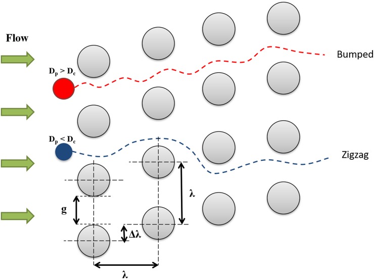
DLD is a size-based separation technique that utilizes the asymmetric bifurcation of laminar flow around the embedded microposts which are placed in a tilted array inside the device.1,36 This array of microposts influences a small suspension displacement according to hydrodynamic forces that emerge under flow conditions. There is a so-called critical diameter (Dc) defined in these devices to predict the suspended particle's displacement as it passes through the array of microposts. Any particle with the diameter less than critical diameter will follow a zigzag pattern without displacing laterally (Dp < Dc in Fig. 1). On the other hand, a particle with a diameter greater than the critical diameter of the device will cross streamlines and follow a bumped pattern, displacing laterally as it passes through the device (Dp > Dc in Fig. 1). In other words, the array of microposts in DLD devices is in such a specific arrangement that precisely controls the trajectory of the particles and facilitates the separation of particles larger and smaller than a critical diameter.
FIG. 1.
Geometrical parameters of DLD post array. g is the gap distance between the two adjacent posts, λ is the center-to-center distance of adjacent posts, Dc is the critical diameter of the device, and Dp is the particle diameter. Note that the red particle (Dp > Dc) follows the bumped mode, while the blue one (Dp < Dc) follows the zigzag mode.
In DLD devices, the row shift fraction (ɛ) is a geometrical parameter defined as Δλ/λ, where Δλ is the shifted distance between microposts and λ is the distance from center-to-center of adjacent microposts. Regarding the lateral row shifting of microposts in DLD device, tilted angle (θ) develops and represents the slope of post arrays. Also, a period number (N) is defined in DLD devices. When the posts of row N + 1 are in the same lateral position as the first row, the period is said to be N. For DLD devices, these parameters are related by
| (1) |
As proposed by the known existing theory, the critical diameter of a DLD device is a function of its geometry in which29
| (2) |
where w is a parameter defined as
| (3) |
Equations (2) and (3) are obtained analytically by assuming a conventional parabolic flow profile through the gap between two adjacent microposts, as well as no slip boundary condition at the micropost walls. This model demonstrates how critical diameter depends on the post geometry configuration, specifically on the gap between posts and the offset of posts in one row with respect to another.29
III. MODEL DESCRIPTION
To study particles/cells passing through the DLD device at moderate to high Re regime, we develop a multiphysics model coupling the Navier–Stokes fluid solver and particle tracing in Sec. III A. In this approach, particles/cells are transported by hydrodynamic forces generated in a DLD device containing hundreds of microposts. The developed multiphysics model is utilized to investigate the overall device performance at moderate to high Re. Note that in this research, we define Re based on the average velocity and gap size between two adjacent posts perpendicular to the fluid flow. Next, in Sec. III B, the liquid droplet model, which has been effectively used for CTC modeling,37,38 is introduced to study the localized cell–post interaction in more details.
A. Transport of particles at moderate to high Re regime
A particle tracing model is developed to track the transport of particles in a fluid using FEM. Since we are working at finite Re, the effects of fluid inertia and viscosity are present simultaneously. Hence, for solving the fluid dynamic, the Navier–Stokes equation is used in conjunction with the continuity equation as
| (4) |
| (5) |
where bold symbols denote vectors and , , p, and μ are fluid density, velocity, pressure, and viscosity, respectively. I is the identity matrix. In this work, it is assumed that in the beginning, the microfluidic system is filled with the fluid and then the particles are injected into the inlet chamber. Thus, the initial fluid has only one phase and the volumetric fraction of particles is too low (less than 10%) to affect the fluid flow.39 In order to find the particle trajectory, the hydrodynamic forces applied by the fluid on the particles should be considered comprehensively. The particle trajectory is then predicted by integrating the force balance on the particle as following:40
| (6) |
The first term on the right-hand side is the drag force which is applied opposite to the particle motion. As the particle slip velocity that describes the relative motion between the particle and the flow is relatively small, the finite Re of the particle remains very small. Therefore, correction to drag coefficient due to finite Re of the particle is neglected here.41 However, it has been shown that when a particle is close to the wall, there is an increase in drag force and there is a need for applying corrections to the drag for considering the particle/wall interaction.42 Note that these corrections can have a great influence on the overall particle behavior specifically in DLD designs, where the fate of each particle is decided in the vicinity of the posts. In this work, the drag force is separated into two independent components for motion parallel and perpendicular to the wall in the form of correction factors and . Hence, the drag components are
| (7a) |
| (7b) |
where is the viscosity of the fluid, is the particle radius, is the fluid flow velocity, and is the particle velocity. The most commonly used expressions for and are derived using the “method of reflections” and represented in terms of power series.43 Note that the exact solutions for the effective wall drag force do not have a closed analytical form in most cases and there are only a few exceptions such as a sphere moving near flat wall. Here, we assume that the suspended particle is sphere shaped and considerably smaller as compared to the size of obstacles in the fluid. Under such conditions, it would be reasonable to employ the correction coefficients for a particle moving near a flat wall as derived by Brenner et al.44 as
| (8a) |
| (8b) |
where z is the distance from the center of the spherical particle to the wall. At moderate to high Re and high flow velocities, one might expect that the particle inertia plays a role such that the equations of motion for the particles itself should contain various memory and other terms. The second term on the right-hand side of Eq. (6) is the so-called Basset force which is due to the change in fluid around the accelerating sphere. The relative importance of the Basset force, which causes complication in the straightforward solution, compared to the drag is governed by the parameter , defined as45
| (9) |
where is the particle mass and is the virtual (added) mass which accounts for the inertia added to the system due to the accelerating body inside the fluid. It can be shown that45 for the spherical particles, the added mass can be calculated by . By substitution, the , which demonstrates the dominancy of the drag force over the Basset force, and, thus, we can neglect this force. The last term on the right-hand side is the Saffman force which is the lift force due to the shear and considers the wall lift effect in our model that manifests due to the geometry of the DLD.46 This force can be calculated as45
| (10) |
where is the deformation tensor, K is the constant of 2.954, and ν is the kinematic viscosity of the fluid. To be mentioned that the Saffman lift force expression in Eq. (10) is restricted to small particle Re. Also, the particle Re based on the particle-fluid velocity difference must be smaller than the square root of the particle Re based on the shear field which is the case in this work. Moreover, as the injected particles are considered much smaller than the post diameter, utilizing Eq. (10) should not introduce considerable errors here. Note that there are several recent works done by Bhattacharya et al. for some interesting inertia effects of the flow on suspended particles. Radial lift on suspended finite-sized particles in narrow conduit systems47–49 or the Basset type force due to translation–rotation coupling for non-spherical particles50,51 is among such effects. In this work, suspended particles are sphere shaped and considerably smaller as compared to the size of obstacles in the fluid. Under such conditions, the radial lift and the Basset type force due to translation–rotation coupling become insignificant49,51 and are thus neglected in our model. Finally, for the wall boundary, the bounce condition was employed, which specularly reflects the suspended particles from the DLD posts in the channel after the collision such that their momentum is conserved. This condition is typically used when tracing microscopic particles in a fluid with obstacles.52–54 Also, the constant inlet boundary condition is set at the entrance of the microchannel and pressure outlet boundary condition is applied at the outlet (see Fig. 2).
FIG. 2.
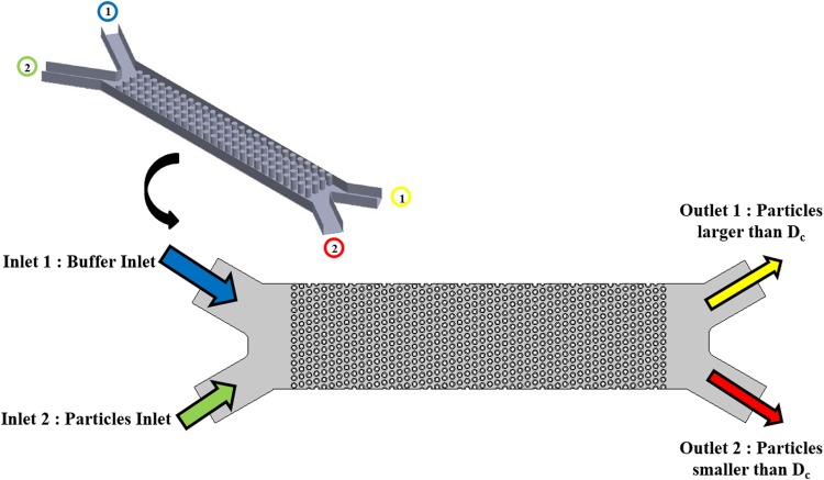
Geometry of the studied microchip based on the DLD concept. The device consists of two inlets for the particles and buffer, the array of microposts, and two outlets for separating the particles based on the size compared to critical diameter.
B. Transport of deformable CTCs at moderate to high Re regime
To study the localized cell–post interaction, we employ the liquid droplet model for CTCs and focus on hydrodynamic interactions between the cell and microposts. For this purpose, the two-phase level-set method (LSM) is utilized for tracking the interface of the CTCs inside the DLD device. The level-set function [φ(x,t)] is assigned to the space occupied by the interface, where x demonstrates the position of a point inside that space at a time t.55 Here, we have used modified LSM, which was initially introduced by Olsson and Kreiss56 and has demonstrated high order accuracy and good mass conservation. In this scheme, φ = 0.5 is assigned for level-set function on the interface contour, φ = 0 for the continuous (first) phase, and for the dispersed (second) phase, φ = 1. Note that in our study, the cell is the dispersed phase and the surrounding medium is the continuous phase.
The governing equations consist of the Navier–Stokes equation and continuity equation, coupled with the level-set equation. Physically, Eqs. (11a) and (11b) are solved to obtain the velocity field, which is then used in Eq. (11c) for the advection of the level-set function as
| (11a) |
| (11b) |
| (11c) |
where n is the unit normal vector to the interface pointing into the droplet, ɛ and γ are numerical stabilization parameters, where ɛ is the thickness of the interface and γ is the reinitialization parameter, and φ is the level-set function. Note that the last term in Eq. (11a) denotes the surface tension force, where σ is the surface tension at the interface, κ is the curvature of the interface which defines as κ = ∇⋅n, and δ is the function concentrated at the interface. Also, note that the density and viscosity, which are used in the above equations, are based on the properties of each phase and level-set function as
| (12) |
| (13) |
The equations are solved using COMSOL Multiphysics in order to track the particle/CTC inside the DLD microdevice. The wetted wall boundary condition is employed in order to consider the contact angle effect in cell/post collision. Table I gives the utilized parameters for the cell properties.
TABLE I.
Cell properties for the baseline design study.
IV. RESULTS AND DISCUSSION
A. Model validation
Prior to investigating the effect of high Re on DLD devices, we validate our particle tracing modeling results with the previous experimental data of Inglis et al.29 and their proposed theoretical critical size at creeping flow (see Fig. 3). To be mentioned that the mesh convergence study is carried out on the velocity profile between the two adjacent posts to select the optimum refinement level, which saves computation time while producing the estimated outcome.
FIG. 3.
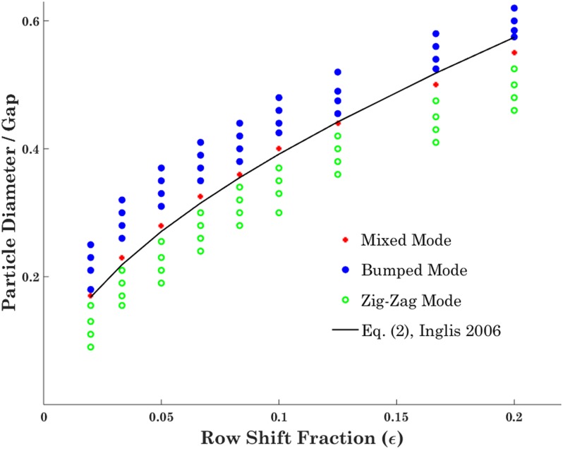
Numerical model validation through comparing the theoretical critical diameter with different modes of rigid particle motion inside the DLD device for different values of ɛ; the results show good match between theoretical and numerical results.
Particles of different sizes are injected into various DLD devices, and their trajectories are tracked utilizing the developed numerical model. Figure 3 demonstrates the different types of motion observed in DLD devices with various row shift fractions. Note that there is a narrow range for the injected particle size, so-called mixed regime, which is the transition of the zigzag toward the bumped mode, and it would be expected that critical size of the device resides in this region. As it could be noticed from Fig. 3, there is a good agreement between our numerical results and the theoretical critical size based on Eq. (2) at creeping flow. There is a small difference between the numerical and theoretical results, especially in higher row shift fractions, which is due to the assumption of parabolic flow profile made in obtaining the theoretical formula.
In the next step, we investigate the performance of the DLD device using the liquid droplet model for CTCs and compare its performance with the particle tracing model. To the best of our knowledge, the liquid droplet model has not been previously used for DLD devices. Therefore, we compare simulations for particles with the droplet model with very high surface tension to see how close the results are in the limiting case. Only for this section, we conduct the simulation with the liquid droplet surface tension of 0.05 N/m, which is the highest one reported for CTC in the literature.62 Several DLD devices with different row shift fractions were modeled, and the cells with various sizes have been tracked. MATLAB codes are developed to measure the area change of the cells as they pass through the microchip, utilizing the image processing functions. Specifically, the edge detection technique is employed for tracking the boundaries of the deformed cell by detecting the discontinuities in brightness within images.
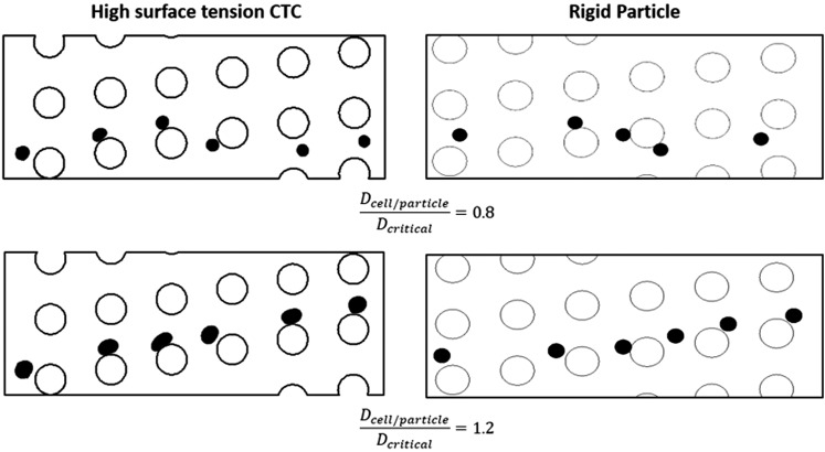
Our results show that the liquid droplet model can distinguish the different modes of motion in the DLD device. In Fig. 4, results for the same DLD device with ɛ = 0.1666, one using the validated particle tracing model and the other with liquid droplet model, has been demonstrated.
FIG. 4.
Comparing the liquid droplet model in its limiting case with high surface tension with validated particle tracing one. The figures on the left-hand side are out of the liquid droplet simulation with high surface tension (σ = 0.05 N/m), while the figures on the right-hand side are from rigid particle tracing model. As it can be noticed, both models are predicting similar behavior for the cells/particles with smaller and larger diameter compared to the critical size of the device.
As it could be noticed from this figure, both models predict similar behavior for the cells/particles with smaller and larger diameter compared to the critical size of the device in the same DLD device. The CTCs which are larger than theoretical critical diameter follow bumped mode, while the ones smaller than critical diameter follow the zigzag mode. This comparison shows that liquid droplet model is capable of capturing the CTC behavior in DLD devices accurately and can provide us further insight into this separation technique.
B. Separation of particles at moderate to high Re regime
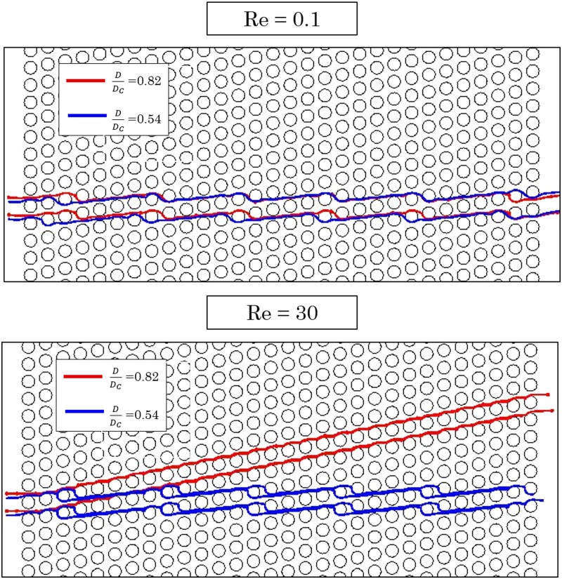
The current theory of DLD devices is developed for the creeping flow regime. In order to study the DLD performance at moderate to high Re regime, two types of particles [the smaller one with and the larger one with where D is particle diameter and Dc is the critical diameter of the device based on the current theory Eq. (2)] are injected into the same DLD device with , and their trajectories are followed at different flow regimes, one in the creeping regime (Re = 0.1) and the other in the moderate Re regime (Re = 30), as shown in Fig. 5.
FIG. 5.
Trajectories of particles from two different sizes in a DLD device with ɛ = 1/5. Note that at creeping flow, both particles follow the zigzag mode since they are smaller than the critical size of the device. However, the same particles follow different trajectories within the same device working at moderate Re regime.
As can be observed from Fig. 5, the trajectories of the larger particles switch from zigzag to bumped mode as the operating flow rate is increased. Note that the device is still capable of separating particles of different sizes. However, the critical size of the device has been changed as a result of increasing the flow rates.
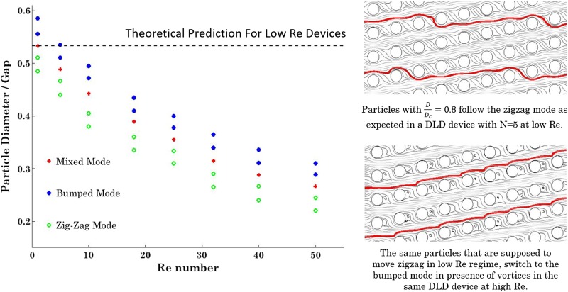
In order to study the effect of Re on the critical size of a DLD device, particles of different sizes are injected into the DLD device with and their trajectories are tracked utilizing the developed numerical model. Figure 6 demonstrates the three different modes of motion of particles at moderate to high Re regime. It would be expected that the calculated critical size of the device at each Re resides in the mixed mode region.
FIG. 6.
Different modes of motion of rigid spherical particles for a DLD device with ɛ = 0.2 at different Re numbers.
As shown in Fig. 6, there is a sharp decrease in the calculated critical size from Re = 10 to Re = 30. In higher Re and consequently higher flow rates, the effects of microposts' walls and lift forces would manifest and cause further displacement for the particles. From Re = 30 to Re = 50, where the vortices are already developed, the rate of decrease in critical diameter declines. As shown in the streamline plots on the right side of Fig. 6, the presence of the vortices in higher Re prevents the particles to follow the zigzag mode and causes further lateral displacement of particles. These modeling results are in line with the experimental results we have observed in Ref. 24. The current theoretical critical size based on Eq. (2) is plotted as a dashed line, which is shown unable to predict the particle behavior in DLD devices working at moderate to high Re regime.
In order to develop a practical formula for predicting the performance of DLD devices working at moderate to high Re regime, the critical size of various devices are calculated numerically and plotted in Fig. 7(a).
FIG. 7.
Critical diameter measurement for DLD devices with different row shift fractions (ɛ). (a) shows the data out of numerical simulation and (b) shows the data derived from the proposed formula [Eq. (14)]. The results from the numerical modeling and proposed formula are showing a good match with a correlation coefficient of 0.96.
Over two hundred sets of simulations are performed for capturing trajectories of particles of different sizes, and the critical size of various DLD devices is determined at different Res. As shown in Fig. 7(a), the critical size of the device declines with decreasing row shift fraction and increasing Re, as expected. Note that as the row shift fraction decreases, which means the microposts are less tilted, the rate in change of the critical size becomes smaller as the Re increases. Multivariable curve fitting is performed based on the numerical data set, and the following formula is proposed for the critical size prediction of moderate to high Re DLD devices,
| (14) |
where g is the gap between two adjacent posts and ɛ is the row shift fraction. The correlation coefficient evaluates the strength of the relationship between the regressed outputs and numerical results.63,64 The correlation coefficient between the numerical data set and data derived from Eq. (14) is found to be 0.96, which indicates that the proposed formula predicts the device performance quite well. Note that in the creeping flow regime when Re ≪ 1, the calculated critical diameter utilizing Eq. (14) matches quite well with the critical diameter based upon the current theory [Eq. (3)] (correlation coefficient of 0.99). In Table II, we compare the critical size obtained from the proposed formula [Eq. (14)] with the known existing theory [Eqs. (2) and (3)] for different row shift fractions and Res. As can be found from Table II, at low Re, the proposed formula and the known existing theory result in similar critical size predictions (below 4% relative error) as it was validated in Sec. IV A, while at higher Re, the deviations become apparent.
TABLE II.
Comparing the critical size from the proposed formula with the known existing theory.
C. Separation of deformable cells (CTCs) at moderate to high Re regime
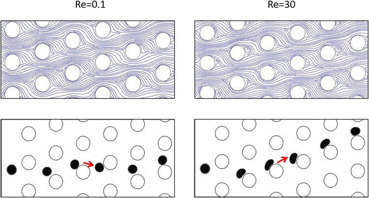
In order to further study the DLD separation performance of deformable cells at moderate to high Re regime, we employ the liquid droplet model for a cell. A CTC with a diameter of 14 μm and a surface tension coefficient of 0.02 N/m has been injected inside the DLD device with ɛ = 0.333 and Dc = 20 μm. Previously, it was demonstrated experimentally that the deformed cell switched to the zigzag mode even in the creeping flow regime. This reduction in the lateral displacement is attributed to the distortion of the cell shape due to shear stress on the cells as they pass through the device and interact with the pillars.65 As shown in Fig. 8, in the creeping flow regime, since the CTC diameter is less than the critical size of the device, it follows the zigzag mode. On the other hand, the same CTC switches to the bumped mode as entering into the moderate to high Re regime.
FIG. 8.
Effect of vortices on cell trajectory. A cell in higher Re regime and in the presence of vortices changes its trajectory to the bumped mode. The critical size, gap between adjacent posts, and cell size are the same for both cases.
Note that at higher Re regime, the cell experiences a noticeable deformation resulting in a decrease of its apparent size, which tends to cause the cell to move zigzag. Conversely, vortices tend to increase the apparent hydrodynamic size of the posts and consequently reduce the effective gap length between adjacent posts. This phenomenon would result in the decrease of the critical size of the DLD device and, thus, cause a bumped motion of the cell which was supposed to move zigzag according to its apparent size. Hence, in moderate to high Re regime, for deformable cells, like CTCs, the effects of vortices and cell deformation are simultaneously involved. In Fig. 8, our results show the dominancy of the vortex and wall effect over the cell deformation.
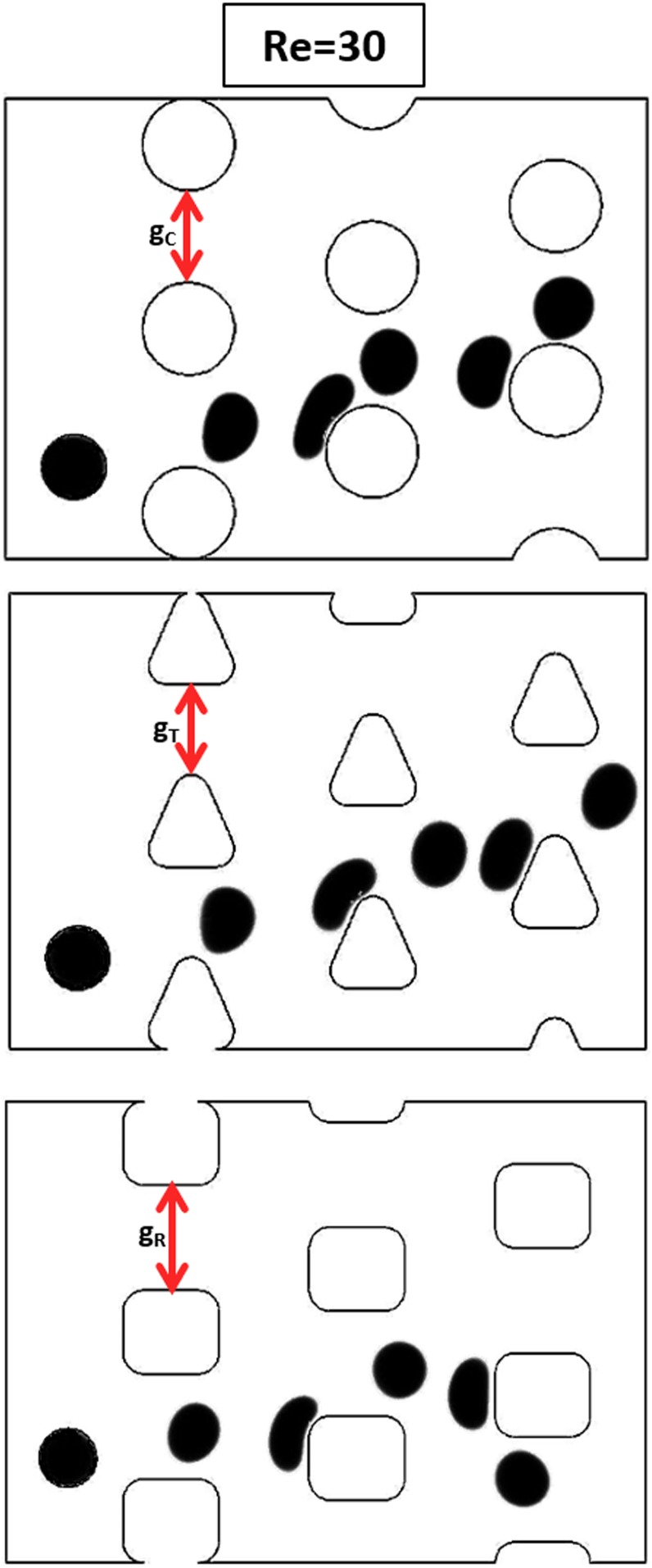
As could be noticed from Fig. 8, raising the vortices would disturb the streamlines and would cause the cells to move on the bumped mode rather than the zigzag motion. The same phenomenon has been observed utilizing particle tracing model in Sec. IV B. To study the post–cell interaction and evaluate its effect on cell motion behavior at moderate to high Re regime, we employ three different post shapes (circle, triangle, and square) for the DLD designs (Fig. 9). These post geometries are chosen to represent the curved (circle), sloped (triangle), and straight (square) surfaces, respectively. Based on the work by Zhang et al.,66 which provides a formula for predicting the critical size for triangular and square post designs at creeping flow, the gap between two adjacent posts has been adjusted to set the critical size the same in all three designs. In all of the following three cases, the Re is set as 30, and the cell diameter is set as 14 μm.
FIG. 9.
Effect of post shape on cell trajectory at moderate to high Re regime. In order to keep the critical size same for different post shapes, the gap between two adjacent posts is calculated based on Ref. 66, which results in gR > gT > gC. The injected cells in all three designs are of the same size. Note that for the circular and triangular posts, the cell follows the bumped mode, while in the device with square posts, it follows the zigzag mode.
Figure 9 shows that a cell trajectory can be affected by the post shape, as expected. Previously in Fig. 8, we have shown that in devices with circular posts, the vortex and wall effect dominates the cell deformation effect at the same Re, resulting in the bumped motion of the cell. The same phenomenon can be observed for both devices with circular and triangular posts (see Fig. 9). However, in the device with square posts, the cell shows different motion behavior. This is associated with the different balance of the vortex and cell deformation effects.
In Fig. 10, the streamlines around the posts in these different designs at Re = 30 are demonstrated. As it can be observed, the vortices behind the square posts are significantly smaller in size than those in the other two designs. As a result, the apparent hydrodynamic size of the square post is almost not affected, while in the other two designs, the apparent hydrodynamic sizes are significantly changed due to the drastic decrease in the effective gap length. Hence, the vortex effect is more prominent in devices with circular and triangular posts compared with the device with a square post. Therefore, the cell deformation effect plays a more important role in the square post design, resulting in the zigzag motion behavior.
FIG. 10.
Fluid streamlines around different post shapes. The vortices behind the square post are significantly smaller in size than those in the other two designs.
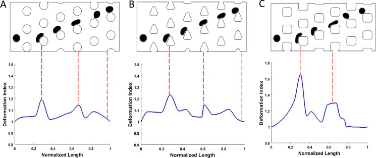
In order to achieve a better understanding of cell deformation effect in these devices, we define a dimensionless deformation index to quantify the post–cell interaction. This index represents the ratio between the perimeters of the deformed and the initial cell. As the cell–post interaction for the zigzag motion is less significant compared to that for the bumped motion, we set the cell diameter to 17 μm, which is large enough so that at Re = 30, the cells follow the bumped mode in all three designs. Figure 11 demonstrates the cell deformation along with the deformation index for the different designs.
FIG. 11.
Cell deformation in DLD devices with different post geometries. The device with rectangular posts (c) results in more deformation in cell compared to devices with circular (a) and triangular (b) posts.
As shown in Fig. 11, for the three configurations we have here, although the Re is the same, the cell experiences less deformation in devices with circular and triangular posts compared to the device with square posts. The largest cell deformation occurs when the cell impacts the corner of the square microposts. However, the cell quickly recovers its initial shape as soon as the interaction with the post finishes. The difference in cell–post interaction would result in different apparent sizes of the cell. In these designs, the cell size is chosen to be significantly larger than the critical size of the devices so that its trajectory is mostly affected by the flow streamlines rather than any local effects such as the vortex formation or cell deformation. However, when the cell size becomes closer to the critical size of a device, the combined effects of the vortices and cell deformation can highly affect the cell trajectory. This explains why, in Fig. 9, the cell shows different transport modes, although the critical size of the three devices is the same. Regarding the smoother post–cell interaction with the curved and sloped sidings, the cell deformation is less significant for circular and triangular posts, and they show better performance compared to the straight siding collision, which tends to extend the cell–post interaction.
V. CONCLUDING REMARKS AND FUTURE WORK
In this research, we study the continuous separation of particles/cells utilizing DLD technique at moderate to high Re regime. A numerical model is developed to predict the particle behavior for high-throughput DLD devices, considering all the effective hydrodynamic forces. The effects of the micropost wall and vortices on device performance are investigated, and a practical formula is proposed for the prediction of the critical size of high-throughput DLD devices. Our results show that the critical size decreases with increasing Re. To better understand how deformable cells behave in high-throughput DLD devices, a liquid droplet model is employed as a mechanical model for CTCs. Our results show that in high-throughput DLD devices, the effects of vortices and cell deformation are simultaneously involved. Three different post shapes are employed for studying the cell–post interaction with curved, sloped, and straight sidings. To quantify the cell–post interaction, a dimensionless deformation index is introduced and compared for different designs. Our results indicate that the gentle post–cell interaction with the curved and sloped sidings in circular and triangular designs facilitates the cell movement better compared with the rough straight siding collision in square post designs. The results presented here could serve as design guidelines for high-throughput DLD separation devices.
Future work involves studying the effects of cell viscosity and surface tension as determinant factors for cell motion in the DLD device as they affect the cell deformation. In addition, coupling the liquid droplet model with other proposed models for adhesion of living cells to the walls67 can be used to study the localized cell–wall interaction. Finally, due to the intrinsic limitation of the liquid droplet model to truly mimic cell behavior under large deformations, more accurate mechanical models of CTCs can be employed in order to consider the intercellular structure of the living cells, especially in high-throughput DLD device where the shear rates have significant impacts on cells.
Note: This paper is part of the special issue on Microfluidics, Circulating Biomarkers and Cancer.
REFERENCES
- 1.Huang L. R., Cox E. C., Austin R. H., and Sturm J. C., “Continuous particle separation through deterministic lateral displacement,” Science 304(5673), 987–990 (2004). 10.1126/science.1094567 [DOI] [PubMed] [Google Scholar]
- 2.Bowman T., Frechette J., and Drazer G., “Force driven separation of drops by deterministic lateral displacement,” Lab Chip 12(16), 2903–2908 (2012). 10.1039/c2lc40234c [DOI] [PubMed] [Google Scholar]
- 3.Wunsch B. H., Smith J. T., Gifford S. M., Wang C., Brink M., Bruce R. L., Austin R. H., Stolovitzky G., and Astier Y., “Nanoscale lateral displacement arrays for the separation of exosomes and colloids down to 20 nm,” Nat. Nanotechnol. 11, 936 (2016). 10.1038/nnano.2016.134 [DOI] [PubMed] [Google Scholar]
- 4.Vanapalli S. A., Duits M. H., and Mugele F., “Microfluidics as a functional tool for cell mechanics,” Biomicrofluidics 3(1), 012006 (2009). 10.1063/1.3067820 [DOI] [PMC free article] [PubMed] [Google Scholar]
- 5.Choi J., Hyun J.-c., and Yang S., “On-chip extraction of intracellular molecules in white blood cells from whole blood,” Sci. Rep. 5, 15167 (2015). 10.1038/srep15167 [DOI] [PMC free article] [PubMed] [Google Scholar]
- 6.Zeming K. K., Salafi T., Chen C.-H., and Zhang Y., “Asymmetrical deterministic lateral displacement gaps for dual functions of enhanced separation and throughput of red blood cells,” Sci. Rep. 6, 22934 (2016). 10.1038/srep22934 [DOI] [PMC free article] [PubMed] [Google Scholar]
- 7.Karabacak N. M., Spuhler P. S., Fachin F., Lim E. J., Pai V., Ozkumur E., Martel J. M., Kojic N., Smith K., Chen P.-I., Yang J., Hwang H., Morgan B., Trautwein J., Barber T. A., Stott S. L., Maheswaran S., Kapur R., Haber D. A., and Toner M., “Microfluidic, marker-free isolation of circulating tumor cells from blood samples,” Nat. Protoc. 9, 694 (2014). 10.1038/nprot.2014.044 [DOI] [PMC free article] [PubMed] [Google Scholar]
- 8.Inglis D. W., Morton K. J., Davis J. A., Zieziulewicz T. J., Lawrence D. A., Austin R. H., and Sturm J. C., “Microfluidic device for label-free measurement of platelet activation,” Lab Chip 8(6), 925–931 (2008). 10.1039/b800721g [DOI] [PubMed] [Google Scholar]
- 9.Jin C., McFaul S. M., Duffy S. P., Deng X., Tavassoli P., Black P. C., and Ma H., “Technologies for label-free separation of circulating tumor cells: from historical foundations to recent developments,” Lab Chip 14(1), 32–44 (2014). 10.1039/C3LC50625H [DOI] [PubMed] [Google Scholar]
- 10.Hur S. C., Mach A. J., and Di Carlo D., “High-throughput size-based rare cell enrichment using microscale vortices,” Biomicrofluidics 5(2), 022206 (2011). 10.1063/1.3576780 [DOI] [PMC free article] [PubMed] [Google Scholar]
- 11.Alix-Panabières C. and Pantel K., “Circulating tumor cells: Liquid biopsy of cancer,” Clin. Chem. 59(1), 110–118 (2013). 10.1373/clinchem.2012.194258 [DOI] [PubMed] [Google Scholar]
- 12.Alix-Panabières C. and Pantel K., “Technologies for detection of circulating tumor cells: Facts and vision,” Lab Chip 14(1), 57–62 (2014). 10.1039/C3LC50644D [DOI] [PubMed] [Google Scholar]
- 13.Gascoyne P. and Shim S., “Isolation of circulating tumor cells by dielectrophoresis,” Cancers 6(1), 545–579 (2014). 10.3390/cancers6010545 [DOI] [PMC free article] [PubMed] [Google Scholar]
- 14.Liu Z., Huang F., Du J., Shu W., Feng H., Xu X., and Chen Y., “Rapid isolation of cancer cells using microfluidic deterministic lateral displacement structure,” Biomicrofluidics 7(1), 011801 (2013). 10.1063/1.4774308 [DOI] [PMC free article] [PubMed] [Google Scholar]
- 15.Mark D., Haeberle S., Roth G., von Stetten F., and Zengerle R., “Microfluidic lab-on-a-chip platforms: Requirements, characteristics and applications,” Chem. Soc. Rev. 39(3), 1153–1182 (2010). 10.1039/b820557b [DOI] [PubMed] [Google Scholar]
- 16.McGrath J., Jimenez M., and Bridle H., “Deterministic lateral displacement for particle separation: A review,” Lab Chip 14(21), 4139–4158 (2014). 10.1039/C4LC00939H [DOI] [PubMed] [Google Scholar]
- 17.Bowman T. J., Drazer G., and Frechette J., “Inertia and scaling in deterministic lateral displacement,” Biomicrofluidics 7(6), 064111 (2013). 10.1063/1.4833955 [DOI] [PMC free article] [PubMed] [Google Scholar]
- 18.Gossett D. R., Weaver W. M., Mach A. J., Hur S. C., Tse H. T. K., Lee W., Amini H., and Di Carlo D., “Label-free cell separation and sorting in microfluidic systems,” Anal. Bioanal. Chem. 397(8), 3249–3267 (2010). 10.1007/s00216-010-3721-9 [DOI] [PMC free article] [PubMed] [Google Scholar]
- 19.Hur S. C., Tse H. T. K., and Di Carlo D., “Sheathless inertial cell ordering for extreme throughput flow cytometry,” Lab Chip 10(3), 274–280 (2010). 10.1039/B919495A [DOI] [PubMed] [Google Scholar]
- 20.Mach A. J., Kim J. H., Arshi A., Hur S. C., and Di Carlo D., “Automated cellular sample preparation using a centrifuge-on-a-chip,” Lab Chip 11(17), 2827–2834 (2011). 10.1039/c1lc20330d [DOI] [PubMed] [Google Scholar]
- 21.Hur S. C., Choi S. E., Kwon S., and Di Carlo D., “Inertial focusing of non-spherical microparticles,” Appl. Phys. Lett. 99(4), 044101 (2011). 10.1063/1.3608115 [DOI] [Google Scholar]
- 22.Lubbersen Y. S., Schutyser M. A. I., and Boom R. M., “Suspension separation with deterministic ratchets at moderate Reynolds numbers,” Chem. Eng. Sci. 73(Suppl. C), 314–320 (2012). 10.1016/j.ces.2012.02.002 [DOI] [Google Scholar]
- 23.Lubbersen Y. S., Dijkshoorn J. P., Schutyser M. A. I., and Boom R. M., “Visualization of inertial flow in deterministic ratchets,” Sep. Purif. Technol. 109(Suppl. C), 33–39 (2013). 10.1016/j.seppur.2013.02.028 [DOI] [Google Scholar]
- 24.Dincau B. M., Aghilinejad A., Hammersley T., Chen X., and Kim J.-H., “Deterministic lateral displacement (DLD) in the high Reynolds number regime: High-throughput and dynamic separation characteristics,” Microfluid. Nanofluid. 22(6), 59 (2018). 10.1007/s10404-018-2078-9 [DOI] [Google Scholar]
- 25.Dincau B. M., Aghilinejad A., Chen X., Moon S. Y., and Kim J. H., “Vortex-free high-Reynolds deterministic lateral displacement (DLD) via airfoil pillars,” Microfluid. Nanofluid. 22(12), 137 (2018). 10.1007/s10404-018-2160-3 [DOI] [Google Scholar]
- 26.Dincau B., Aghilinejad A., Kim J.-H., and Chen X., “Characterizing the high Reynolds number regime for deterministic lateral displacement (DLD) devices,” in Proceedings of ASME 2017 International Mechanical Engineering Congress and Exposition (American Society of Mechanical Engineers, 2017), pp. V010T13A033. [Google Scholar]
- 27.Loutherback K., D'Silva J., Liu L., Wu A., Austin R. H., and Sturm J. C., “Deterministic separation of cancer cells from blood at 10 mL/min,” AIP Adv. 2(4), 042107 (2012). 10.1063/1.4758131 [DOI] [PMC free article] [PubMed] [Google Scholar]
- 28.Liu Z., Zhang W., Huang F., Feng H., Shu W., Xu X., and Chen Y., “High throughput capture of circulating tumor cells using an integrated microfluidic system,” Biosens. Bioelectron. 47, 113–119 (2013). 10.1016/j.bios.2013.03.017 [DOI] [PubMed] [Google Scholar]
- 29.Inglis D. W., Davis J. A., Austin R. H., and Sturm J. C., “Critical particle size for fractionation by deterministic lateral displacement,” Lab Chip 6(5), 655–658 (2006). 10.1039/b515371a [DOI] [PubMed] [Google Scholar]
- 30.Loutherback K., Chou K. S., Newman J., Puchalla J., Austin R. H., and Sturm J. C., “Improved performance of deterministic lateral displacement arrays with triangular posts,” Microfluid. Nanofluid. 9(6), 1143–1149 (2010). 10.1007/s10404-010-0635-y [DOI] [Google Scholar]
- 31.Rahmati M., Alavi S. R., and Tavakoli M. R., “Investigation of heat transfer in mechanical draft wet cooling towers using infrared thermal images: An experimental study,” Int. J. Refrig. 88, 229–238 (2018). 10.1016/j.ijrefrig.2017.11.031 [DOI] [Google Scholar]
- 32.Shahali P., Rahmati M., Alavi S. R., and Sedaghat A., “Experimental study on improving operating conditions of wet cooling towers using various rib numbers of packing,” Int. J. Refrig. 65, 80–91 (2016). 10.1016/j.ijrefrig.2015.12.004 [DOI] [Google Scholar]
- 33.Ye S., Shao X., Yu Z., and Yu W., “Effects of the particle deformability on the critical separation diameter in the deterministic lateral displacement device,” J. Fluid Mech. 743, 60–74 (2014). 10.1017/jfm.2014.22 [DOI] [Google Scholar]
- 34.Quek R., Le D. V., and Chiam K.-H., “Separation of deformable particles in deterministic lateral displacement devices,” Phys. Rev. E 83(5), 056301 (2011). 10.1103/PhysRevE.83.056301 [DOI] [PubMed] [Google Scholar]
- 35.Krüger T., Holmes D., and Coveney P. V., “Deformability-based red blood cell separation in deterministic lateral displacement devices—A simulation study,” Biomicrofluidics 8(5), 054114 (2014). 10.1063/1.4897913 [DOI] [PMC free article] [PubMed] [Google Scholar]
- 36.Aghaamoo M., Aghilinejad A., Chen X., and Xu J., “On the design of deterministic dielectrophoresis for continuous separation of circulating tumor cells from peripheral blood cells,” Electrophoresis 40(10), 1486–1493 (2019). 10.1002/elps.201800459 [DOI] [PubMed] [Google Scholar]
- 37.Aghaamoo M., Zhang Z., Chen X., and Xu J., “Deformability-based circulating tumor cell separation with conical-shaped microfilters: Concept, optimization, and design criteria,” Biomicrofluidics 9(3), 034106 (2015). 10.1063/1.4922081 [DOI] [PMC free article] [PubMed] [Google Scholar]
- 38.Zhang Z., Xu J., Hong B., and Chen X., “The effects of 3D channel geometry on CTC passing pressure–Towards deformability-based cancer cell separation,” Lab Chip 14(14), 2576–2584 (2014). 10.1039/C4LC00301B [DOI] [PubMed] [Google Scholar]
- 39.Shamloo A., Selahi A., and Madadelahi M., “Designing and modeling a centrifugal microfluidic device to separate target blood cells,” J. Micromech. Microeng. 26(3), 035017 (2016). 10.1088/0960-1317/26/3/035017 [DOI] [Google Scholar]
- 40.Maxey M. R. and Riley J. J., “Equation of motion for a small rigid sphere in a nonuniform flow,” Phys. Fluids 26(4), 883–889 (1983). 10.1063/1.864230 [DOI] [Google Scholar]
- 41.Goldman A. J., Cox R. G., and Brenner H., “Slow viscous motion of a sphere parallel to a plane wall—I motion through a quiescent fluid,” Chem. Eng. Sci. 22(4), 637–651 (1967). 10.1016/0009-2509(67)80047-2 [DOI] [Google Scholar]
- 42.Lin B., Yu J., and Rice S. A., “Direct measurements of constrained Brownian motion of an isolated sphere between two walls,” Phys. Rev. E 62(3), 3909 (2000). 10.1103/PhysRevE.62.3909 [DOI] [PubMed] [Google Scholar]
- 43.Lobry L. and Ostrowsky N., “Diffusion of Brownian particles trapped between two walls: Theory and dynamic-light-scattering measurements,” Phys. Rev. B 53(18), 12050 (1996). 10.1103/PhysRevB.53.12050 [DOI] [PubMed] [Google Scholar]
- 44.Happel J. and Brenner H., Low Reynolds Number Hydrodynamics: With Special Applications to Particulate Media, Vol. 1 ( Springer Science & Business Media, 2012). [Google Scholar]
- 45.Durst F. and Raszillier H., “Analysis of particle-wall interaction,” Chem. Eng. Sci. 44(12), 2871–2879 (1989). 10.1016/0009-2509(89)85097-3 [DOI] [Google Scholar]
- 46.Saffman P. G. T., “The lift on a small sphere in a slow shear flow,” J. Fluid Mech. 22(2), 385–400 (1965). 10.1017/S0022112065000824 [DOI] [Google Scholar]
- 47.Bhattacharya S. and Navardi S., “Radial lift on a suspended finite-sized sphere due to fluid inertia for low-Reynolds-number flow through a cylinder,” J. Fluid Mech. 722, 159–186 (2013). 10.1017/jfm.2012.636 [DOI] [Google Scholar]
- 48.Navardi S. and Bhattacharya S., “Axial pressure-difference between far-fields across a sphere in viscous flow bounded by a cylinder,” Phys. Fluids 22(10), 103305 (2010). 10.1063/1.3489350 [DOI] [Google Scholar]
- 49.Bhattacharya S., Gurung D. K., and Navardi S., “Radial distribution and axial dispersion of suspended particles inside a narrow cylinder due to mildly inertial flow,” Phys. Fluids 25(3), 033304 (2013). 10.1063/1.4791794 [DOI] [Google Scholar]
- 50.Bhattacharya S., “Unsteady hydrodynamic effect of rotation on steady rigid-body motion,” J. Fluid Mech. 538, 291–308 (2005). 10.1017/S002211200500532X [DOI] [Google Scholar]
- 51.Bhattacharya S., “History force on an asymmetrically rotating body in Poiseuille flow inducing particle migration across a slit pore,” Phys. Fluids 20(9), 093301 (2008). 10.1063/1.2974827 [DOI] [Google Scholar]
- 52.Aghilinejad A., Aghaamoo M., Chen X., and Xu J., “Effects of electrothermal vortices on insulator-based dielectrophoresis for circulating tumor cell separation,” Electrophoresis 39(5-6), 869–877 (2018). 10.1002/elps.201700264 [DOI] [PubMed] [Google Scholar]
- 53.Aghaamoo M., Aghilinejad A., and Chen X., “Numerical study of insulator-based dielectrophoresis method for circulating tumor cell separation,” Proc. SPIE 10061, 100611A (2017). 10.1117/12.2260759 [DOI] [Google Scholar]
- 54.Aghilinejad A., Aghaamoo M., and Chen X., “Numerical study of joule heating effect on dielectrophoresis-based circulating tumor cell separation,” in Proceedings of ASME 2017 International Mechanical Engineering Congress and Exposition (American Society of Mechanical Engineers, 2017), pp. V003T04A014. [Google Scholar]
- 55.Bashir S., Rees J. M., and Zimmerman W. B., “Simulations of microfluidic droplet formation using the two-phase level set method,” Chem. Eng. Sci. 66(20), 4733–4741 (2011). 10.1016/j.ces.2011.06.034 [DOI] [Google Scholar]
- 56.Olsson E. and Kreiss G., “A conservative level set method for two phase flow,” J. Comput. Phys. 210(1), 225–246 (2005). 10.1016/j.jcp.2005.04.007 [DOI] [Google Scholar]
- 57.Becker F. F., Wang X.-B., Huang Y., Pethig R., Vykoukal J., and Gascoyne P., “Separation of human breast cancer cells from blood by differential dielectric affinity,” Proc. Natl. Acad. Sci. U.S.A. 92(3), 860–864 (1995). 10.1073/pnas.92.3.860 [DOI] [PMC free article] [PubMed] [Google Scholar]
- 58.Gascoyne P. R., Wang X. B., Huang Y., and Becker F. F., “Dielectrophoretic separation of cancer cells from blood,” IEEE Trans. Ind. Appl. 33(3), 670–678 (1997). 10.1109/28.585856 [DOI] [PMC free article] [PubMed] [Google Scholar]
- 59.Zhang X., Hashem M. A., Chen X., and Tan H., “On passing a non-Newtonian circulating tumor cell (CTC) through a deformation-based microfluidic chip,” Theor. Comput. Fluid Dyn. 32(6), 753–764 (2018). 10.1007/s00162-018-0475-z [DOI] [Google Scholar]
- 60.Hur S. C., Henderson-MacLennan N. K., McCabe E. R., and Di Carlo D., “Deformability-based cell classification and enrichment using inertial microfluidics,” Lab Chip 11(5), 912–920 (2011). 10.1039/c0lc00595a [DOI] [PubMed] [Google Scholar]
- 61.Gonzalez-Rodriguez D., Guevorkian K., Douezan S., and Brochard-Wyart F., “Soft matter models of developing tissues and tumors,” Science 338(6109), 910–917 (2012). 10.1126/science.1226418 [DOI] [PubMed] [Google Scholar]
- 62.Zhang Z., Chen X., and Xu J., “Entry effects of droplet in a micro confinement: Implications for deformation-based circulating tumor cell microfiltration,” Biomicrofluidics 9(2), 024108 (2015). 10.1063/1.4916645 [DOI] [PMC free article] [PubMed] [Google Scholar]
- 63.Alavi S. R. and Rahmati M., “Experimental investigation on thermal performance of natural draft wet cooling towers employing an innovative wind-creator setup,” Energy Convers. Manage. 122, 504–514 (2016). 10.1016/j.enconman.2016.06.016 [DOI] [Google Scholar]
- 64.Rahmati M., Alavi S. R., and Tavakoli M. R., “Experimental investigation on performance enhancement of forced draft wet cooling towers with special emphasis on the role of stage numbers,” Energy Convers. Manage. 126, 971–981 (2016). 10.1016/j.enconman.2016.08.059 [DOI] [Google Scholar]
- 65.Holmes D., Whyte G., Bailey J., Vergara-Irigaray N., Ekpenyong A., Guck J., and Duke T., “Separation of blood cells with differing deformability using deterministic lateral displacement,” Interface Focus 4(6), 20140011 (2014). 10.1098/rsfs.2014.0011 [DOI] [PMC free article] [PubMed] [Google Scholar]
- 66.Zhang Z., Henry E., Gompper G., and Fedosov D. A., “Behavior of rigid and deformable particles in deterministic lateral displacement devices with different post shapes,” J. Chem. Phys. 143(24), 243145 (2015). 10.1063/1.4937171 [DOI] [PubMed] [Google Scholar]
- 67.N’dri N. A., Shyy W., and Tran-Son-Tay R., “Computational modeling of cell adhesion and movement using a continuum-kinetics approach,” Biophys. J. 85(4), 2273–2286 (2003). 10.1016/S0006-3495(03)74652-9 [DOI] [PMC free article] [PubMed] [Google Scholar]


