Abstract

Graphene oxide (GO) is an amorphous 2D material, which has found widespread use in the fields of chemistry, physics, and materials science due to its similarity to graphene with the benefit of being far easier to synthesize and process. However, the standard of GO characterization is very poor because its structure is irregular, being sensitive to the preparation method, and it has a propensity to transform due to its reactive nature. Atomistic simulations of GO are common, but the nanostructure in these simulations is often based on little evidence or thought. We have written a computer program to generate graphene oxide nanostructures for general purpose atomistic simulation based on theoretical and experimental evidence. The structures generated offer a significant improvement to the current standard of randomly placed oxidized functional groups and successfully recreate the two-phase nature of oxidized and unoxidized graphene domains observed in microscopy experiments. Using this model, we reveal new features of GO structure and predict that a critical point in the oxidation reaction exists as the oxidized region reaches a percolation threshold. Even by a conservative estimate, we show that, if the carbon to oxygen ratio is kept above 6, a continuous aromatic network will remain, preserving many of graphene’s desirable properties, irrespective of the oxidation method or the size distribution of graphene sheets. This is an experimentally achievable degree of oxidation and should aid better GO synthesis for many applications.
Introduction
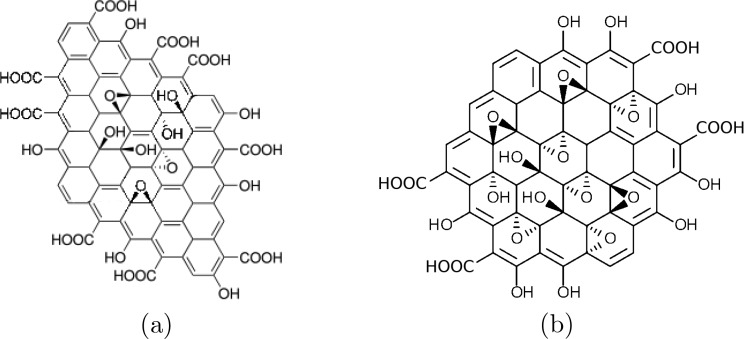
There is no precise consensus about the nanostructure of graphene oxide.1 The Lerf-Klinowski model2 (Figure 1a) is widely recognized and has formed the basis of much scientific research.3,4 This model assumes an uncorrelated random distribution of epoxy and alcohol groups on the surfaces, with alcohol and carboxyl groups around the edges. However, correlation between oxidized sites seems chemically intuitive: isolated carbon double bonds are more reactive than conjugated/aromatic systems;5 indeed, several experiments have shown the presence of oxidized and unoxidized regions.6−9 A comprehensive understanding of how this pattern could evolve does not exist. Yang et al.10 enlightened this discussion by studying the various reactive intermediate structures that could occur in graphene oxidation, using quantum mechanical calculations. They predict that oxidation is so overwhelmingly favored adjacent to already oxidized carbons that separate large oxidized and aromatic regions are inevitable. The behavior of the material will clearly depend on the distribution and morphology of these regions. Until now, however, simulations aimed at understanding the nanoscale electronic and mechanical behavior of graphene oxide have used approximate models based on the Lerf-Klinowski model.3,4 Notwithstanding this, we posit that randomly distributed oxygen containing groups represent an unnecessarily poor approximation for the description of graphene oxide (GO).
Figure 1.
(a) Lerf-Klinowski model of the structure of graphene oxide.2 Their work established that the major functional groups are carboxylic acids and alcohol groups on the edges and expoxy and alcohol groups on the surface. This basic pattern has been confirmed by many experiments.2 (b) A circumcoronene molecule oxidized using our algorithm. This model relies on the same assumptions as to which functional groups exist, but the groups are added sequentially based on the relative reactivity of unoxidized sites.
Graphene oxide is most often made by the Hummers’ method,11,12 where potassium permangenate oxidizes graphite in an acidic solution. This method will typically make GO with a carbon to oxygen ratio (C/O) of 2.13 C/O is a popular metric to characterize GO because it is experimentally easy to obtain and gives a simple measure of the extent of oxidization; it will be used throughout this study. The rate of oxidization at a graphitic site via permanganate, MnO4–, is predominantly influenced by the stability of the intermediate structure: graphene-MnO4–.10,14 Yang et al.10 found that the intermediate state is made more stable by the breaking of adjacent π-bonds, steric availability, and hydrogen bond formation with the MnO4– ion. An important conclusion from Yang et al.’s10 work and our analysis is that, once a graphene sheet has been oxidized, the rate of oxidation adjacent to an oxidized site is very likely to be more than 1020 times faster than at a pristine graphene site. An initial oxidation reaction on pristine graphene then acts as a nucleation site from which more oxidation can proliferate. The disruption of the sp2 network, and the structure of that disruption, is well-known to have an effect on the mechanical and electronic properties of the resulting material.15,16 Therefore, we must study the structure of the GO produced by this method to get a better understanding of its properties.
In this study, we first present a method to build large atomistic models of graphene oxide based on the local reactivity of graphene systems. We then use results from this model to study the continuum percolation threshold of graphene oxide systems.
Methods
Atomistic Model
We used a machine learning approach to extend the subset of reactive sites Yang et al.10 studied to any possible reactive site that could be encountered on a graphene oxide sheet. Through this method, we can generate graphene oxide structures based on empirical and theoretical observations rather than a random generation, which is currently the norm. This method is encapsulated within a program that systematically oxidizes graphitic structures for atomistic simulation.17 The program is freely available and can generate structures for a variety of simulation requirements; here, we will describe and assess the structures generated.
Given the small training set from Yang et al.’s10 work, we found that many machine learning techniques did not perform well when predicting the reactivity of different sites. The available data is far too sparse to train a neural network. However, a decision tree or random forest (RF) approach worked well (probably because the feature set is discrete). For example, the number of alcohol groups above the plane that are one bond away from a reactive carbon–carbon bond is an integer ranging from 0 to 4. Each reactive site then has 8 features: two different oxidation types that can be a first or second neighbor above or below the plane. We used the Scikit-learn library to generate our RF model, which had a maximum depth of 4 whose output is the mean of 500 estimators.18 For information on generating the feature sets and validation of the RF model, see the Supporting Information.
An example of a very small graphene flake oxidized using our program is shown in Figure 1b. At this scale, it looks similar to the Lerf-Klinowski model, but the location of the oxygen containing groups is highly correlated. The most obvious difference comes when larger areas are oxidized, as seen in Figure 2: the large oxidized region propagates from its nucleation site, and structures emerge such as two phases of oxidized and unoxidized domains and aromatic pockets within the oxidized island.
Figure 2.
Representative example of a 50 × 50 nm2 graphene sheet nucleated and oxidized systematically using the approach described in the main text; evolution of the oxidized region is depicted through (a–d). Aromatic carbons: gray; oxidized carbons: blue; oxygen: red; hydrogen: white.
The structures generated are qualitatively similar to high-resolution microscopy images of graphene oxide;6−9 specifically, amorphous alcohol and epoxy groups make up the oxidized regions with unoxidized islands on the nanometer scale. A random placement of oxygen containing functional groups, as described by the Lerf-Klinowski model, would not recreate these inhomogeneous phases.
The training data available is probably biased toward highly reactive sites (because the most reactive sites were of interest in the original study), and so the termination of our builder is less reliable. The average predicted reactivity of oxidized sites starts to decrease at a carbon oxygen ratio of C/O ≈ 2, comparable to the experiment, for which simple oxidation of graphene normally gives the same ratio.13
Percolation Analysis
The atomic structure of GO (shown in Figures 1b and 2) may have important implications for its physical properties and interactions with other molecules, including other GO sheets. It is valuable to have an accurate way to generate this structure, but the arrangement of alcohol and epoxy groups within an oxidized region does not itself appear to form a discernible pattern. The structure and evolution of these oxidized regions, however, is of great importance. Here, we design a model to study the properties of this two-phase system.
It is obvious from Figure 2 that GO could be approximated to a two-phase system, namely, a purely graphitic phase and a graphene oxide phase, which increases in size. To study the mesoscale evolution of a graphene sheet undergoing oxidization, we constructed a continuum model.19
The reactions requiring consideration are
| 1 |
| 2 |
where G denotes a graphitic site, the subscript r designates a reactive site (i.e., near to an already oxidized graphitic carbon), and the subscript O indicates an oxygenated site. kn and krx are the rate constants of the nucleation and catalyzed reactions, respectively; as discussed above, krx ≫ kn. After a graphene sheet is nucleated by an oxygen site, GO, we consider the oxidation reaction as a propagating circle around that nucleation site, a reasonable approximation as one can see from the shape of the island in Figure 2 (approximating the boundary of an island is discussed in more detail in the Supporting Information).
Considering a propagating oxidized island
of radius r, on a very large graphene sheet, the
area of oxidized graphene is AO = πr2. The
reactive area of graphene Ar is defined
as the narrow strip, of width w, around the circumference
of the oxidized island: Ar = π [(r + w)2 – r2)] ≈ 2πrw (when w < r), with w approximately
the length of a carbon bond. Rearranging, we find  .
.
As discussed above, the oxidation of graphene is limited by the formation of the graphene-MnO4– intermediate structure; we assume the reaction is elementary and construct the rate law for eq 2:
| 3 |
Assuming that the concentration of MnO4– remains constant (in the experiment, it is added in excess), we have
| 4 |
| 5 |
Recalling AO = πr2, we can see from eq 4 that the radius of an oxidized island grows at a constant rate.
We model a graphene sheet as a square; the oxygenation is nucleated at a random point, and the oxidized island’s radius increases at a constant rate. What we are primarily interested in here is identifying the percolation threshold: past the tipping point where there is no continuous area of conjugated aromatic carbons, we can expect its electrical and mechanical properties to steeply degrade. We define the percolation threshold of this system as occurring when there is no continuously connected path in physical terms that connects opposite edges of the square via unoxidized regions of graphene; i.e., it cannot conduct electrically from one edge to another. This is a special case of an established problem in mathematics of finding the 2D continuum percolation threshold with fully penetrable disks.20−22
For the case where the rate of nucleation, kn, is insignificant compared to krx, there will be only one oxidized island present. By observing atomic precision images of graphene oxide,6−9 it is clear that nucleation of oxidized regions happens at more than one point on a graphene sheet. While oxidation may be vastly (1020 times) faster near oxidized sites than pristine graphene, we know that most samples of graphene are not pristine and contain many defects. These defects could feasibly encourage nucleation, raising kn, the rate of nucleation. We can then predict the effect of the ratio of krx and kn on the resulting material. From now, we absorb [MnO4–] into the rate constant for clarity:
| 6 |
where A is the total area of graphene and Ar is the strip of graphene of width w adjacent to all oxidized graphene sites. With the possibility of several nucleation sites, so that propagating islands can overlap, this problem must be approached numerically.
It can be seen that all sets of systems that satisfy Akn/krx = χ behave identically when considering the fractional coverage at the percolation threshold, ϕ(tc), where χ is a dimensionless constant that characterizes the system. For example, a larger system, which has a slower nucleation rate, would reach its percolation threshold at the same fractional coverage. We use a unit area sheet and krx = 1 s–1 for simplicity; we also assume that krx is independent of kn, and we use different values of kn to assess all possible systems.
The algorithm advances as follows: (1) a nucleation site (node) is added to a square cell; (2) the island centered on each node has its radius increased by δr; (3) new island nodes are added; (4) repeat steps 2–4 until no continuous unoxidized region exists. In step 2, δr is proportional to δtkrx√A. Step 3 is achieved by adding a number of new nodes drawn from a Poisson distribution with mean knAδt, only accepting nodes that fall in unoxidized regions. The procedure terminates when a path can be made from one edge to its opposite with overlapping islands (see Figure 3). For periodic 2D systems, this has been postulated many times to be equivalent to the percolation threshold.20−22 Here, we apply it to a nonperiodic system as graphene sheets have edges.
Figure 3.
Typical example of a graphene oxidation simulation. The algorithm is described in the main text. A node is added at step 0. Pink regions represent oxidized regions. The simulation is stopped at step 20 768, when a continuously connected path can be made from one edge to its opposite, shown by the green line. δt = 10–5 s–1.
Results
The fraction of graphene that has been oxidized at time t is ϕ(t). The critical time at which the percolation threshold is reached is denoted tc. If the algorithm reports that a path can be made between two opposite edges with oxidized regions at time t′, we know that tc lies between t′ and t′ – δt. We therefore report the cell coverage at the percolation threshold as
| 7 |
The fractional coverage in Figure 4 is reported as the average of 10 000 simulation runs. Error bars are the 95% confidence interval based on a bootstrap analysis on the simulation runs plus the algorithmic error, taken as the average value of eq 7. Reducing δt increases the accuracy of each run; however, the additional computational cost means fewer simulations can be run, so the confidence interval increases. Results are within the error for different values of δt, showing that our results are independent of the variable δt.
Figure 4.

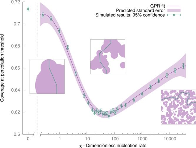
Variation of percolation threshold by varying χ = Akn/krx. By varying χ, all unique systems can be tested. At low values, the system tends to a percolation threshold of 0.71; a minimum is reached at χ = 45, before rising logarithmically. Data from our simulations are shown in green; a curve fit and confidence interval are shown in purple, fit via a Gaussian process regression. Snapshots of typical simulations at the percolation threshold with different values of χ are shown in boxes. Purple areas correspond to oxidized islands. The green lines indicate the first path that can be made from one edge to its opposite; i.e., there is no longer a continuously connected unoxidized region.
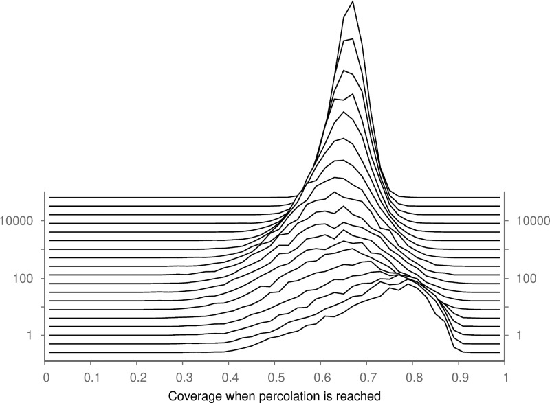
From Figure 4, we can see that a minimum percolation threshold exists when χ = 45. Below this value, the model has fewer islands and more coverage is required to reach the percolation threshold, tending asymptotically to a value of 0.71 for a system where no additional nucleation is permitted (χ = 0). Above χ = 45, the percolation threshold rises logarithmically; we did not simulate higher values of χ as precision errors in the model become more pronounced, and no new behavior is observed. The mechanism that underlies this relationship between χ and ϕ(c) is not known, but the competing mechanisms are interesting. Asymmetries, similar to this case, in the percolation threshold of circles with different radii have been observed before,21 but the origin of this phenomenon has not been explained. The distribution of coverage at the percolation threshold is shown in Figure 5.
Figure 5.
Distribution of fractional coverage at percolation thresholds for different values of χ. The distribution becomes narrower as the nucleation rate increases.
Figure 4 demonstrates that the minimum coverage required to reach the percolation threshold for any combination of reaction rates and flake sizes is 0.62. We can also show that, whatever the value of χ (i.e., for any distribution of graphene sheets), at least 95% of the sheets produced will not have reached the percolation threshold if the coverage is below 0.46 (see Supporting Information). The C/O ratio of a propagating oxidized region is at most 2.92 (calculated using our atomistic graphene oxide builder;17 see Supporting Information). All this means, by a conservative estimate, that the percolation threshold for C/O ratios is no greater than 2.92/0.46 = 6.3. We conclude that, if the formation reaction of graphene oxide could be quenched before this point, i.e., if the C/O ratio exceeds 6.3, many of graphene’s mechanical and electrical properties could be preserved.
This prediction is also borne out by our atomistic model. Using different nucleation rates, kn, that spanned several orders of magnitude, the percolation threshold was reached at an average C/O ratio of 4.2 and never exceeded 4.5.
Conclusion
We have provided a systematic method to build accurate GO structures and use this nanoscale knowledge to gain understanding of its macroscale structure. This method is encapsulated into a program released alongside this manuscript,17,19 offering a significant improvement to the Lerf-Klinowski model commonly used in constructing GO structures. To our knowledge, this is the first analysis of the percolation threshold in a graphene oxide synthesis reaction. It is important that GO models have two distinct domains present on the nanoscale, rather than a homogeneous distribution of functional groups. Models that generate random amorphous regions of oxidized graphene will not vary significantly in their results; in contrast, structures that have large separate aromatic and oxidized domains will drastically affect properties such as aggregation, exfoliation, solvation, and adsorption, since the two domains have very different long-range interaction characteristics.
In particular, by keeping the C/O ratio above 6, a continuous domain of conjugated carbon atoms will exist, improving the mechanical and electronic properties of GO. We hope that this will serve to inform experimentalists as well as modelers and help predict the characteristic behavior of GO, while improving the consistency with which GO can be synthesized.
Acknowledgments
We thank the Engineering and Physical Sciences Research Council (EPSRC) for a studentship for R.C.S. P.V.C. is grateful for funding provided by UKCOMES High-End Computing Consortium (www.ukcomes.org) under the EPSRC Grant No. EP/L00030X/1. The authors acknowledge funding from the European Union’s Horizon 2020 research and innovation programme for the VECMA project (www.vecma.eu) under Grant No. 800925. We are grateful to Robin Richardson, David Wright, and James Suter for helpful comments and stimulating discussions while the work was in progress.
Supporting Information Available
The Supporting Information is available free of charge on the ACS Publications website at DOI: 10.1021/acs.jcim.9b00114.
The authors declare no competing financial interest.
Supplementary Material
References
- Dreyer D. R.; Park S.; Bielawski C. W.; Ruoff R. S. The chemistry of graphene oxide. Chem. Soc. Rev. 2010, 39, 228–240. 10.1039/B917103G. [DOI] [PubMed] [Google Scholar]
- Lerf A.; He H.; Forster M.; Klinowski J. Structure of Graphite Oxide Revisited. J. Phys. Chem. B 1998, 102, 4477–4482. 10.1021/jp9731821. [DOI] [Google Scholar]
- Shih C.-J.; Lin S.; Sharma R.; Strano M. S.; Blankschtein D. Understanding the pH-Dependent Behavior of Graphene Oxide Aqueous Solutions: A Comparative Experimental and Molecular Dynamics Simulation Study. Langmuir 2012, 28, 235–241. 10.1021/la203607w. [DOI] [PubMed] [Google Scholar]
- Dai H.; Xu Z.; Yang X. Water Permeation and Ion Rejection in Layer-by-Layer Stacked Graphene Oxide Nanochannels: A Molecular Dynamics Simulation. J. Phys. Chem. C 2016, 120, 22585–22596. 10.1021/acs.jpcc.6b05337. [DOI] [Google Scholar]
- Trömel M.; Russ M. Dimanganheptoxid zur Selektiven Oxidation Organischer Substrate. Angew. Chem. 1987, 99, 1037–1038. 10.1002/ange.19870991009. [DOI] [Google Scholar]
- Pacilé D.; Meyer J.; Fraile Rodríguez A.; Papagno M.; Gómez-Navarro C.; Sundaram R.; Burghard M.; Kern K.; Carbone C.; Kaiser U. Electronic Properties and Atomic Structure of Graphene Xxide Membranes. Carbon 2011, 49, 966–972. 10.1016/j.carbon.2010.09.063. [DOI] [Google Scholar]
- Cai W.; Piner R. D.; Stadermann F. J.; Park S.; Shaibat M. A.; Ishii Y.; Yang D.; Velamakanni A.; An S. J.; Stoller M.; An J.; Chen D.; Ruoff R. S. Synthesis and Solid-State NMR Structural Characterization of 13C-Labeled Graphite Oxide. Science 2008, 321, 1815–7. 10.1126/science.1162369. [DOI] [PubMed] [Google Scholar]
- Saxena S.; Tyson T. A.; Negusse E. Investigation of the Local Structure of Graphene Oxide. J. Phys. Chem. Lett. 2010, 1, 3433–3437. 10.1021/jz1014339. [DOI] [Google Scholar]
- Erickson K.; Erni R.; Lee Z.; Alem N.; Gannett W.; Zettl A. Determination of the Local Chemical Structure of Graphene Oxide and Reduced Graphene Oxide. Adv. Mater. 2010, 22, 4467–4472. 10.1002/adma.201000732. [DOI] [PubMed] [Google Scholar]
- Yang J.; Shi G.; Tu Y.; Fang H. High Correlation Between Oxidation Loci on Graphene Oxide. Angew. Chem., Int. Ed. 2014, 53, 10190–10194. 10.1002/anie.201404144. [DOI] [PubMed] [Google Scholar]
- Hummers W. S. Jr; Offeman R. E. Preparation of graphitic oxide. J. Am. Chem. Soc. 1958, 80, 1339–1339. 10.1021/ja01539a017. [DOI] [Google Scholar]
- Marcano D. C.; Kosynkin D. V.; Berlin J. M.; Sinitskii A.; Sun Z.; Slesarev A.; Alemany L. B.; Lu W.; Tour J. M. Improved Synthesis of Graphene Oxide. ACS Nano 2010, 4, 4806–4814. 10.1021/nn1006368. [DOI] [PubMed] [Google Scholar]
- Wick P.; Louw-Gaume A. E.; Kucki M.; Krug H. F.; Kostarelos K.; Fadeel B.; Dawson K. A.; Salvati A.; Vázquez E.; Ballerini L.; Tretiach M.; Benfenati F.; Flahaut E.; Gauthier L.; Prato M.; Bianco A. Classification Framework for Graphene-Based Materials. Angew. Chem., Int. Ed. 2014, 53, 7714–7718. 10.1002/anie.201403335. [DOI] [PubMed] [Google Scholar]
- Dash S.; Patel S.; Mishra B. K. Oxidation by Permanganate: Synthetic and Mechanistic Aspects. Tetrahedron 2009, 65 (4), 707–739. 10.1016/j.tet.2008.10.038. [DOI] [Google Scholar]
- Pei Q. X.; Zhang Y. W.; Shenoy V. B. A Molecular Dynamics Study of the Mechanical Properties of Hydrogen Functionalized Graphene. Carbon 2010, 48, 898–904. 10.1016/j.carbon.2009.11.014. [DOI] [PubMed] [Google Scholar]
- Chen D.; Feng H.; Li J. Graphene Oxide: Preparation, Functionalization, and Electrochemical Applications. Chem. Rev. 2012, 112, 6027–6053. 10.1021/cr300115g. [DOI] [PubMed] [Google Scholar]
- Sinclair R. C.velocirobbie/make-graphitics; 2019; 10.5281/zenodo.2642230. [DOI]
- Pedregosa F.; Varoquaux G.; Gramfort A.; Michel V.; Thirion B.; Grisel O.; Blondel M.; Prettenhofer P.; Weiss R.; Dubourg V.; Vanderplas J.; Passos A.; Cournapeau D.; Brucher M.; Perrot M.; Duchesnay E. Scikit-learn: Machine Learning in Python. J. Mach. Learn. Res. 2011, 12, 2825–2830. [Google Scholar]
- Sinclair R. C.velocirobbie/graphene-oxide-percolation 0.1; 2019; 10.5281/zenodo.2554086. [DOI]
- Mertens S.; Moore C. Continuum Percolation Thresholds in Two Dimensions. Phys. Rev. E 2012, 86, 061109. 10.1103/PhysRevE.86.061109. [DOI] [PubMed] [Google Scholar]
- Quintanilla J.; Torquato S.; Ziff R. M. Efficient Measurement of the Percolation Threshold for Fully Penetrable Discs. J. Phys. A: Math. Gen. 2000, 33, L399–L407. 10.1088/0305-4470/33/42/104. [DOI] [Google Scholar]
- Quintanilla J. Measurement of the Percolation Threshold for Fully Penetrable Disks of Different Radii. Phys. Rev. E: Stat. Phys., Plasmas, Fluids, Relat. Interdiscip. Top. 2001, 63, 061108. 10.1103/PhysRevE.63.061108. [DOI] [PubMed] [Google Scholar]
Associated Data
This section collects any data citations, data availability statements, or supplementary materials included in this article.


