Abstract
Conducting polymer actuators have shown wide application prospects in the field of biomedical sensors and micro-/nanorobotics. In order to explore more applications in biomedical sensing and robotics, it is essential to understand the actuator static behavior from an engineering perspective, before incorporating them into a design. In this article, we have established the mathematical model of a trilayer polypyrrole (PPy) cantilever actuator and validated it experimentally. The model helps in enhancing the efficiency and in improving the performance, predictability, and control of the actuator. The thermal expansion analogy, which is similar to volume change of the multilayer PPy actuator due to ion migration, has been considered to develop a mathematical model in COMSOL Multiphysics. To further validate the actuator deformation predicted by the mathematical modeling, a multilayer PPy actuator was fabricated by electrochemical synthesis and the experimentally determined deflection of the actuator was compared to simulation data. Both the theoretical and experimental results depict that the model is effective for predicting the bending behavior of multilayer PPy actuators at different input voltages.
Introduction
As one of the most common conductive polymers for actuators, polypyrrole (PPy) has gained much attention due to low operating power and ease of synthesis.1,2 Compared with the piezoelectric actuators, the conjugated polymer has a relatively small mechanical impedance and modulus of elasticity, high sensitivity, high reversibility, and excellent mechanical properties critical for potential applications in artificial muscles and sensors.3,4 The trilayer PPy actuators operates in a liquid as well as in air medium, generate considerable stress and larger strain output under lower driving power, and are lightweight and biocompatible in nature.5−7 These advantages make them attractive for robotic and biomedical domains, including the biomanipulation, biomimetic systems, biomedical devices, micromanipulation of living cells, sensing, and as artificial muscles for robotics.8−12
The trilayer PPy actuator is an anion-driven device, and the deflection of the actuator is caused by volume change of the conducting polymer due to the redox reaction.13,14 In a trilayer actuator, layers of PPy are separated by the porous insulating film made of polyvinylidene fluoride (PVDF), which contains an electrolyte inside the pores. When dc electric voltage is applied on a PPy actuator, the volume of the PPy film at the positive electrode expands due to oxidation, whereas the film volume shrinks on the negative side because of reduction.15 In this redox reaction, the anions present in the electrolyte transfer to the PPy at the positive terminal and anions at the negative terminal are expelled from the PPy, which leads to the bending of the actuator.16 The processing techniques for fabrication of trilayer PPy actuators have matured; at present, it is necessary to have a quantitative method to describe the PPy actuator’s actuation performance. This quantitative method is the basis of feasibility analysis, design optimization, and actuator control.
There are two basic methods which have been realized to establish the quantitative model. The first method is based on diffusive elastic metal model.17 Subsequent studies coupled the charge transfer model with solid mechanics to predict the PPy actuator deflection.18 The second method is an equivalent model, in which the relation between charge transfer and strain is assumed to be analogous to a thermal expansion.19,20 This investigation is in line with the latter method to simulate PPy deflection, adopting the assumption that the thermal–structure coupling method must be equivalent to the charge transfer. In this work, we have simulated the trilayer actuator by using equivalent thermal expansion coefficient and compared the simulation data with the experimental results. For fabrication of the trilayer actuator, PPy films doped with trifluoromethanesulfonimide are formed by electrosynthesis on either side of a gold-coated PVDF membrane. The actuating properties of the trilayer actuator are investigated and quantified by applying constant potential. The actuator deflection at various voltages is compared with the theoretical modeling results. It is found that the equivalent method is simple and able to predict the deflection of the PPy actuator, which is very helpful for better design and control of future conducting polymer actuators.
Results and Discussions
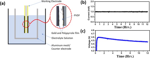
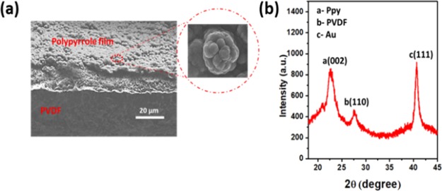
For trilayer actuators, commercially available PVDF films are considered from EMD Millipore, with pores 0.45 μm in size. Both sides of the PVDF sheet were sputtered by gold to make a conductive surface for electrodeposition of the conducting polymer. PVDF membrane (10 × 10 cm2) is mounted on the supporting silicon substrate by using Kapton tape to achieve the deposition of 8 nm gold on one side. The same process was used to deposit gold on the other side of PVDF. To achieve uniform electropolymerization of PPy, the thickness of the gold layer was set at approximately 8–10 nm, which gives the resistivity of about 7–8 Ω cm. The conductive polypyrrole was deposited by the in-house built electrochemical cell, in which a glass beaker consisting of Au/PVDF acts as a working electrode, whereas an aluminum mesh acts as a counter electrode. The mesh covered both sides of Au/PVDF to achieve a uniform coating as shown in Figure 1a. Figures S1 and S2 demonstrate the polymerization setup and fabrication step of the trilayer PPy actuator. This electrochemical synthesis was carried out at −16 °C in the presence of the lithium bis(trifluoromethanesulfonic)imide (LiTFSi) electrolyte by using the chronopotentiometry technique. Highly conductive and crystalline PPy deposition depends upon appropriate voltage and temperature, which enhance the electrical conductivity, molecular anisotropy, and uniform morphology. PPy synthesis at lower temperature produces higher electronic conductivity, longer conjugation length, proper structural order, and fewer structural defects. Solvents such as dimethylformamide (DMF), dimethyl sulphoxide, and pyridine impede the anodic electropolymerization of pyrrole monomer when the pH level is high. Therefore, by considering the effect of the solvent, a slight amount of water (1%) can substantially influence the polymerization process and improve the structure and mechanical properties of the film.21 As illustrated in Figure 1b, constant 1 mA current is passed in between the working electrode and counter electrode for 12 h in the presence of the electrolyte, whereas Figure 1c demonstrated the output voltage. The voltage transient of PPy polymerization exhibits different characteristics during the deposition. In the initial period, a sharp rise of potential is related to the nucleation of the polymer at the gold-deposited PVDF. In the second stage of polymerization, a slight decrease of the potential and, eventually, saturation at some equilibrium level is observed. This transient phase indicates that the monomer starts polymerizing on the surface of Au/PVDF in the presence of the LiTFSi electrolyte.21,22Figure 2a shows the typical cross-section scanning electron microscopy (SEM) image of as-grown PPy layer on the Au/PVDF substrate. It is interesting to know that the coating of PPy film on the Au/PVDF surface is homogenous, compact, and shows globular structures of about 2–5 μm in size. Generally, PPy films deposited at 1 mA current for 12 h Are found to be uniformly thick on both sides and show the cauliflower-type of structure with different sizes.23,24 The size of features on the surface gets larger for longer deposition times. In our case, with a 12 h long deposition, the polymerization period provides good film adhesion as well as good crystalline structure morphology.13Figure 2b demonstrates the sharp X-ray diffraction (XRD) peak of a PPy-deposited film at 2θ = 23.1°, with the relative full width at half maximum at 1.34° and long range XRD with an LiTFSi peak with PPy as demonstrated in the Supporting Information S3.25 This sharp PPy peak results from the fact that the average size of crystalline domains increases with the increase of the polymerization time. However, further increase of polymerization time leads to more crystallinity due to the increase of average particle size of PPy. In our case, deposition longer than 12 h reduced the adhesion between the Au/PVDF and PPy, which was easily peeled out from the substrate.
Figure 1.
Electrosynthesis of PPy on the gold-sputtered PVDF sheet (a) schematic of the electrochemical cell apparatus, (b) input current, and (c) output voltage for 12 h.
Figure 2.
Electrodeposition characteristics of PPy (a) SEM image of trilayer PPy actuator (b) XRD of PPy on Au/PVDF sheet.
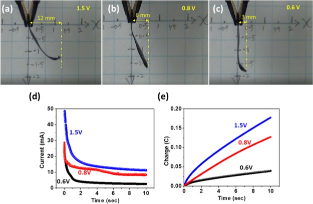
For displacement measurement, the trilayer actuator was gripped in between an alligator clip, allowing the application of different polarity potentials on two sides of the synthesized film. Figure 3a–c shows the tip displacement of the trilayer actuators on different input voltages at 50 mHz (10 s positive and 10 s negative potential).
Figure 3.
Displacement of a trilayer actuator at (a) 1.5, (b) 0.8, and (c) 0.6 V; (d) current profile of a trilayer actuator at 1.5, 0.8, and 0.6 V, and (e) charge transfer at 1.5, 0.8, and 0.6 V.
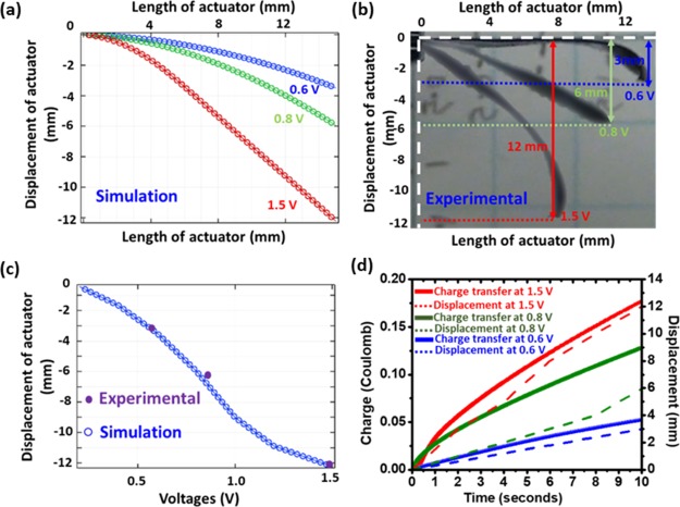
The applied potential was a square wave of three different voltages (±1, ± 0.8, and ±0.6 V). The 1.5 cm × 0.5 cm rectangular area of the fabricated actuator was assessed for tip displacement measurement. At all values of applied potential, tip displacement tended to increase with the increase of the potential; it is found that applying voltage in excess of ±1.5 V results in burning out the grip area and shortening the two terminals. Therefore, the maximal voltage for tip displacement measurement was kept at 1.5 V, at which the bending was as large as 12 mm, whereas at 0.8 and 0.6 V, bending of 6 and 3 mm, respectively, was observed.
The difference in actuation behavior of PPy actuators has been attributed to mass transfer rates and Young’s moduli being different at different voltages. At 1.5 V, the larger strain in PPy-TFSi-doped actuator may be due to the higher charge-transfer rate; this phenomenon illustrates that electrical energy is converted into mechanical energy. Therefore, the strain caused from actuator deformation is proportional to the charge transfer at higher voltages. At a lower potential, however, because of fewer number of ions transferred to the film, the tip displacement is smaller.26,27 A typical current and charge-transfer response under various input voltages is depicted in Figure 3d,e, respectively. It is found that the charge transfer at a higher potential, that is 1.5 V is larger than that at lower voltages. These results indicate that the level to which PPy is oxidized or reduced is higher at a higher potential and this leads to the larger displacement as compared to the case of small potentials, that is 0.8 and 0.6 in the two-electrode configuration. In the following electrochemical evaluation of a multilayer actuator, ±1.5 V potential is applied to determine the charge–discharge current behavior at 50 mHz. Figure S4a represents the input voltage, whereas Figure S4b is the output current, which depicts a similar performance during oxidation and reduction of the conducting polymer.
Simulation
The bending effect in multilayer PPy actuators is caused by the volume change in different layers that associate with the redox reaction. Therefore, the thermal expansion analogy is relevant, in which a load generated due to the volume change is similar to the volume change in a trilayer PPy actuator because of ion migration.
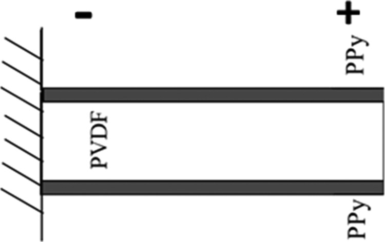
The mathematical modeling of multilayer actuators involves three coupled physics phenomena: electric current conduction, heat conduction with thermal generation, and structural stresses and strains due to thermal expansion. This model can describe the change in the volume due to thermal expansion. COMSOL Multiphysics software was used to solve the mathematical model. The modeled structure consists of three layers in which PVDF is sandwiched between two conducting PPy layer. Figure 4 represents the boundary assumed in the equivalent model.28 The fixed constraints are applied at the left end of the cantilever instead of being clipped by an alligator clip. The voltage was applied from the left to the right sides in order to accelerate the computation time clip. The equivalent thermal expansion coefficient of PPy has been evaluated using the experimental results, whereas the material properties of PVDF and PPy have been set in accordance with the previous work of PPy actuator modeling.5
Figure 4.
Equivalent model of PPy trilayer actuator.
For simulation of the trilayer actuator, the first layer of the thermal expansion coefficient of PPy is set as 0.03/°F, whereas the second layer of PPy thermal expansion coefficient is −0.03/°F, and other material parameters are shown in Table 1. The governing equation used in this study is the heat transfer equation, in which some assumptions have been considered to simplify the model. For instance, (i) the thickness effect is ignored because the thickness is much smaller than the length, (ii) there is no thermal resistance and creep (deformation) between the layers, (iii) the materials parameter is constant, and (iv) coupling of electrophysics and thermal physics is ignored. The heat transfer equation can be written in the form23
| 1 |
where di is the material density, cpi is heat capacity at constant pressure, Vi is the volume, h is the surface combined heat transfer coefficient, S is surface area, R is heater resistance, and U is the applied voltage. Both sides of the eq 1 describe the rate at which the thermodynamic energy is changing, the first terms on both sides of the equation describe the heat flux that flows into the actuator, the second term shows the heat loss from the surface, and the last term is Joule heat.
Table 1. Model Parameters.
| parameters | value | description |
|---|---|---|
| B | 5 mm | width of the actuator |
| L | 15 mm | length of the actuator |
| d1 | 8 μm | thickness of the PPy film |
| d2 | 110 μm | thickness of the pvdf substrate |
| EPPy | 612 MPa | Young’s modulus of PPy |
| EPVDF | 80 MPa | Young’s modulus of PVDF |
| ρPPy | 1150 kg m–3 | density of PPy |
| ρPVDF | 1150 kg m–3 | density of PVDF |
| νPPy | 0.25 | Poisson’s ratio of PPy |
| νPVDF | 0.25 | Poisson’s ratio of PVDF |
| εr,PVDF | 64.92 | relative permittivity of PVDF |
| εr,PPy | 4.5 | relative permittivity of PPy |
| αPPy | 0.03/°F | coefficient of thermal expansion |
| KPPy | 50 W/(m K) | thermal conductivity of PPy |
| KPVDF | 0.12 W/(m K) | thermal conductivity of PVDF |
| CPPy | 1.4 × 10³ J/(kg·K) | heat capacity at constant pressure of PPy |
| CPVDF | 740 J/(kg·K) | heat capacity at constant pressure of PVDF |
| σPPy | 5 × 10³ S/m | electrical conductivity of PPy |
| σPVDF | 1 × 10⁻¹⁰ S/m | electrical conductivity of PVDF |
| V | 0.2, 0.4, 0.6, 0.8, 1.0, 1.2, 1.5 V | applied voltage |
The initial condition
where, for convenience, the zero temperature corresponds to the temperature of the medium surrounding the cantilever.
The boundary conditions are
and
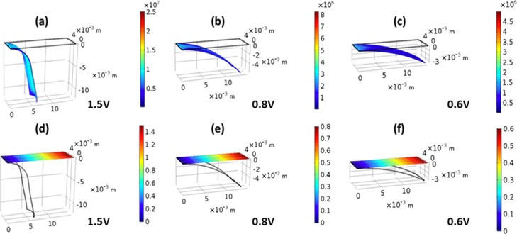
In the simulation, meshing and setting boundary conditions are finished according to the simulation need. The total number of elements is 24267, adopting the free tetrahedral mesh. Three voltages were applied from the fixed constraints (left side) to the tip of the cantilever. The final deflection of the PPy actuator cantilever was obtained from electrothermal–structural coupling simulation techniques as shown in Figure 5. Figure 5a–c illustrates the comparison between deformed and undeformed cantilevers at three different voltages (1.5, 0.8, and 0.6 V). This theoretical modeling agrees with experimental results and shows similar displacement behavior. This modeling is also called the von-Mises stress distribution of the cantilever; the maximum von-Mises stress is distributed on the tip side of the cantilever, which is 25 MPa stress at 1.5 V. Figure 5d–f illustrates the electric potential distribution across the model PPy trilayer cantilever at 1.5, 0.8, and 0.6 V. These simulation results depict that the deflection of the cantilever beam with low potential side is less as compared to the tip in the thermal expansion method.
Figure 5.
Simulation of the trilayer actuator; deflection of the PPy trilayer actuator at (a) 1.5, (b) 0.8, and (c) 0.6 V; electric potential difference across the PPy trilayer actuator at (d) 1.5, (e) 0.8, and (f) 0.6 V.
The simulated deformation of the trilayer PPy actuator at three different potentials, 0.6, 0.8, and 1.5 V is shown in Figure 6a. It is depicted that the displacement tends to increase with the increasing voltage, the red curve is the deformation at the voltage of 1.5 V, and the maximum tip vertical displacement can reach 12.2 mm. Figure 6b shows the experimental deflection of the actuator at three different voltages (1.5, 0.8, and 0.6 V), which demonstrate deflection behavior similar to the numerical model. However, in numerical modeling, the deflection is slightly more, and consistent as compared to the experimental results. This is because of the environmental effect (moisture and oxygen), which leads to the oxidation of the electrolyte and reduces the ion kinetics during the redox reaction.29,30Figure 6c depicts the simulated deformation of the PPy actuator as a function of voltage in the range from 0 to 1.5 V. For comparison, experimental deflection at three voltages (1.5, 0.8, and 0.6 V) in purple dots is shown. Figure 6d illustrates that the simulated displacement of the trilayer actuator is linearly increasing with the respective voltage, which acknowledges the behavior of the conducting polymer actuator, where the charge transfer increases with the increment of potential. The agreement between experiments and simulation behavior of tip displacement validates the feasibility of the equivalent model in the prediction of PPy actuator deformation at various voltages.
Figure 6.
Simulation and Experimental deflection of the trilayer actuator at 1.5, 0.8, and 0.6 V (a) simulation results of tip displacement, (b) experimental tip displacement, (c) tip displacement comparison between experimental and simulation, and (d) plot of charge transfer and displacement for 10 s.
Conclusions
In this study, the static response of a PPy actuator cantilever was characterized experimentally and compared with COMSOL Multiphysics simulation. To explore the bending response of the PPy actuator cantilever, a multilayer PPy actuator was fabricated by electrochemical synthesis via the constant current method. The displacement, charge transfer, and current behavior of the actuator were studied by applying three different potentials. For simulation, thermal expansion analogy, which is similar to the volume change of the multilayer PPy actuator due to ion migration, has been considered to develop the model. The PPy actuators exhibited a similar response in their bending by increasing applied voltage in the simulations as well as the experimental investigations. By comparing theoretical modeling with electrosynthesis of actuators, it is confirmed that the equivalent model is viable for predicting the conducting polymer actuator deformation at different input voltages.
Materials and Methods
Chemicals and Materials
Lithium trifluoromethanesulfonimide (LiTFSi, Sigma-Aldrich), propylene carbonated (Sigma Aldrich), and DMF (Sigma-Aldrich) were all used in pristine condition. PVDF membrane which had a thickness of 110 μm was obtained from Millipore. Pyrrole monomer (Sigma-Aldrich) was distilled and stored −20 °C according to the description at.
Metallization
Gold was deposited (CVC 601 sputter deposition) on both sides of the PVDF film at 2 × 10⁻⁶ mTorr pressure and 30 mA current. The 7 nm Au conducting layer helps in electrodeposition of PPy on each side.
Electrodeposition of PPy
The polymerization method was used to synthesize the trilayer actuator. In this technique, constant current (chronopotentiometry) is passed between the working electrode and the counter electrode using the Biological SP 200 potentiometer. Au-deposited PVDF acted as the working electrode and the aluminum mesh was the counter electrode in the solution, which contains 0.1 M pyrrole dissolved in 0.1 M LiTFSi/PC with 1% water. The polymerization of the PVDF membrane was performed for 12 h at −16 °C with 0.1 mA constant current.
Electromechanical and Simulation Modeling
The electrochemical displacement of the trilayer actuator was acquired by imaging of the actuator with a graph paper placed parallel to the actuator. A high-resolution video camera was used. The actuator input voltage signal was provided by a Biological SP 200 potentiometer, which measures the output current as well as charge transfer during the redox reaction. The simulation of the actuator was performed using the COMSOL Multiphysics software.
Characterization of the Material
XRD patterns recorded with scan rate 0.03·s–1 on a Rigaku Miniflex II (X-ray diffractometer) with Cu Kα source. The SEM analysis was conducted on a JSM-7600 FE SEM. The optical image of the actuator’s cross-section was observed using a Leica DM-RX optical microscope and 1392 × 1040 pixels Lumenera’s INFINITY3S CCD camera with pixel size of 6.45 × 6.45 μm2.
Acknowledgments
S.L. acknowledges the support from Wayne State University, Detroit MI and Shenyang Ligiong University, China.
Supporting Information Available
The Supporting Information is available free of charge on the ACS Publications website at DOI: 10.1021/acsomega.9b00032.
Experimental details: polymerization setup; fabrication steps of PPy actuator; XRD spectra; oxidation and reduction of PPy actuator of full cycle (PDF)
Author Contributions
S.L. and N.M. contributed equally. S.L. conceived and designed all simulation work and N.M., S.V. performed the experimental work. S.L. contributed the writing and editing of the simulation part. N.M., S.V., I.V., and L.M.R.A. have edited and written the experimental work.
The authors declare no competing financial interest.
Supplementary Material
References
- Otero T. F.; Cortés M. T. A sensing muscle. Sens. Actuators, B 2003, 96, 152–156. 10.1016/s0925-4005(03)00518-5. [DOI] [Google Scholar]
- Baughman R. H. Conducting polymer artificial muscles. Synth. Met. 1996, 78, 339–353. 10.1016/0379-6779(96)80158-5. [DOI] [Google Scholar]
- Jager E. W.; Smela E.; Inganäs O. Microfabricating conjugated polymer actuators. Science 2000, 290, 1540–1545. 10.1126/science.290.5496.1540. [DOI] [PubMed] [Google Scholar]
- Shahinpoor M.; Bar-Cohen Y.; Simpson J.; Smith J. Ionic polymer-metal composites (IPMCs) as biomimetic sensors, actuators and artificial muscles-a review. Smart Mater. Struct. 1998, 7, R15. 10.1088/0964-1726/7/6/001. [DOI] [Google Scholar]
- Alici G.; Devaud V.; Renaud P.; Spinks G. Conducting polymer microactuators operating in air. J. Micromech. Microeng. 2009, 19, 025017. 10.1088/0960-1317/19/2/025017. [DOI] [Google Scholar]
- Adeloju S. B.; Wallace G. G. Conducting polymers and the bioanalytical sciences: new tools for biomolecular communications. A review. Analyst 1996, 121, 699–703. 10.1039/an9962100699. [DOI] [PubMed] [Google Scholar]
- Zhang B. G. X.; Spinks G. M.; Gorkin R.; Sangian D.; Di Bella C.; Quigley A. F.; Kapsa R. M. I.; Wallace G. G.; Choong P. F. M. In vivo biocompatibility of porous and non-porous polypyrrole based trilayered actuators. J. Mater. Sci.: Mater. Med. 2017, 28, 172. 10.1007/s10856-017-5979-3. [DOI] [PubMed] [Google Scholar]
- Mazzoldi A.; De Rossi D.. Conductive-polymer-based structures for a steerable catheter, Smart Structures and Materials 2000: Electroactive Polymer Actuators and Devices (EAPAD); International Society for Optics and Photonics, 2000; pp 273–281.
- Jager E. W. H.; Masurkar N.; Nworah N. F.; Gaihre B.; Alici G.; Spinks G. M. Patterning and electrical interfacing of individually controllable conducting polymer microactuators. Sens. Actuators, B 2013, 183, 283–289. 10.1016/j.snb.2013.02.075. [DOI] [Google Scholar]
- Jager E.; Masurkar N.; Nworah N. F.; Gaihre B.; Alici G.; Spinks G. M.. Individually controlled conducting polymer tri-layer microactuators, Solid-State Sensors, Actuators and Microsystems (TRANSDUCERS & EUROSENSORS XXVII). 2013 Transducers & Eurosensors XXVII: The 17th International Conference on, IEEE, 2013; pp 542–545.
- He X.; Li C.; Chen F.; Shi G. Polypyrrole microtubule actuators for seizing and transferring microparticles. Adv. Funct. Mater. 2007, 17, 2911–2917. 10.1002/adfm.200600869. [DOI] [Google Scholar]
- Panda S. K.; Bandopadhya D.. Gold/Polypyrrole (Au/PPy) Bimorph Actuator for Underwater Robotic Motion. 2018 IEEE International Conference on System, Computation, Automation and Networking (ICSCA); IEEE, 2018; pp 1–8.
- Masurkar N.; Jamil K.; Arava L. M. R.. Environmental Effects on the Polypyrrole Tri-Layer Actuator; Actuators, Multidisciplinary Digital Publishing Institute, 2017; p 17. [Google Scholar]
- Venkatesh V.; Katsube N.; Sundaresan V. B. Morphology-dependent mass transport model for mechanoelectrochemistry of polypyrrole. Smart Mater. Struct. 2019, 28, 015001. 10.1088/1361-665x/aaee43. [DOI] [Google Scholar]
- Gaihre B.; Alici G.; Spinks G. M.; Cairney J. M. Synthesis and performance evaluation of thin film PPy-PVDF multilayer electroactive polymer actuators. Sens. Actuators, A 2011, 165, 321–328. 10.1016/j.sna.2010.10.009. [DOI] [Google Scholar]
- Ding J.; Zhou D.; Spinks G.; Wallace G.; Forsyth S.; Forsyth M.; MacFarlane D. Use of ionic liquids as electrolytes in electromechanical actuator systems based on inherently conducting polymers. Chem. Mater. 2003, 15, 2392–2398. 10.1021/cm020918k. [DOI] [Google Scholar]
- Fang Y.; Tan X.; Shen Y.; Xi N.; Alici G. A scalable model for trilayer conjugated polymer actuators and its experimental validation. Mater. Sci. Eng. C 2008, 28, 421–428. 10.1016/j.msec.2007.04.024. [DOI] [Google Scholar]
- Price A. D.; Naguib H. E. A unified multiphysics finite element model of the polypyrrole trilayer actuation mechanism. J. Intell. Mater. Syst. Struct. 2013, 24, 548–558. 10.1177/1045389x12464530. [DOI] [Google Scholar]
- Madden J. D. W.Conducting Polymer Actuators; Massachusetts Institute of Technology, 2000. [Google Scholar]
- Della Santa A.; De Rossi D.; Mazzoldi A. Performance and work capacity of a polypyrrole conducting polymer linear actuator. Synth. Met. 1997, 90, 93–100. 10.1016/s0379-6779(97)81256-8. [DOI] [Google Scholar]
- Ansari R. Polypyrrole conducting electroactive polymers: synthesis and stability studies. E-J. Chem. 2006, 3, 186–201. 10.1155/2006/860413. [DOI] [Google Scholar]
- Harraz F. A. Electrochemical polymerization of pyrrole into nanostructured p-type porous silicon. J. Electrochem. Soc. 2006, 153, C349–C356. 10.1149/1.2185286. [DOI] [Google Scholar]
- Bazzaoui M.; Martins L.; Bazzaoui E.; Martins J. New electrochemical procedure for elaborating homogeneous and strongly adherent PPy films on zinc electrodes. J. Electroanal. Chem. 2002, 537, 47–57. 10.1016/s0022-0728(02)01247-0. [DOI] [Google Scholar]
- Cvetko B.; Brungs M.; Burford R.; Skyllas-Kazacos M. Structure, strength and electrical performance of conducting polypyrroles. J. Mater. Sci. 1988, 23, 2102–2106. 10.1007/bf01115775. [DOI] [Google Scholar]
- Partch R.; Gangolli S.; Matijević E.; Cal W.; Arajs S. Conducting polymer composites: I. Surface-induced polymerization of pyrrole on iron (III) and cerium (IV) oxide particles. J. Colloid Interface Sci. 1991, 144, 27–35. 10.1016/0021-9797(91)90234-y. [DOI] [Google Scholar]
- Alici G.; Metz P.; Spinks G. M. A methodology towards geometry optimization of high performance polypyrrole (PPy) actuators. Smart Mater. Struct. 2006, 15, 243. 10.1088/0964-1726/15/2/003. [DOI] [Google Scholar]
- Alici G.; Mui B.; Cook C. Bending modeling and its experimental verification for conducting polymer actuators dedicated to manipulation applications. Sens. Actuators, A 2006, 126, 396–404. 10.1016/j.sna.2005.10.020. [DOI] [Google Scholar]
- Han L. H.; Lu T. J. Modelling and optimal design of multilayer cantilever microactuators. MRS Online Proc. Libr. 2003, 795, U11.10. 10.1557/proc-795-u10.11. [DOI] [Google Scholar]
- Freire T. J. P.; Gonzalez E. R. Effect of membrane characteristics and humidification conditions on the impedance response of polymer electrolyte fuel cells. J. Electroanal. Chem. 2001, 503, 57–68. 10.1016/s0022-0728(01)00364-3. [DOI] [Google Scholar]
- Wu G.; Hu Y.; Liu Y.; Zhao J.; Chen X.; Whoehling V.; Plesse C.; Nguyen G. T. M.; Vidal F.; Chen W. Graphitic carbon nitride nanosheet electrode-based high-performance ionic actuator. Nat. Commun. 2015, 6, 7258. 10.1038/ncomms8258. [DOI] [PMC free article] [PubMed] [Google Scholar]
Associated Data
This section collects any data citations, data availability statements, or supplementary materials included in this article.


