Abstract
Herein, a magnetically separable reduced graphene oxide (rGO)-supported CoFe2O4–TiO2 photocatalyst was developed by a simple ultrasound-assisted wet impregnation method for efficient photocatalytic H2 production. Integration of CoFe2O4 with TiO2 induced the formation of Ti3+ sites that remarkably reduced the optical band gap of TiO2 to 2.80 eV from 3.20 eV. Moreover, the addition of rGO improved the charge carrier separation by forming Ti–C bonds. Importantly, the CoFe2O4–TiO2/rGO photocatalyst demonstrated significantly enhanced photocatalytic H2 production compared to that from its individual counterparts such as TiO2 and CoFe2O4–TiO2, respectably. A maximum H2 production rate of 76 559 μmol g–1 h–1 was achieved with a 20 wt % CoFe2O4- and 1 wt % rGO-loaded TiO2 photocatalyst, which was approximately 14-fold enhancement when compared with the bare TiO2. An apparent quantum yield of 12.97% at 400 nm was observed for the CoFe2O4–TiO2/rGO photocatalyst under optimized reaction conditions. This remarkable enhancement can be attributed to synergistically improved charge carrier separation through Ti3+ sites and rGO support, viz., Ti–C bonds. The recyclability of the photocatalyst was ascertained over four consecutive cycles, indicating the stability of the photocatalyst. In addition, it is worth mentioning that the photocatalyst could be easily separated after the reaction using a simple magnet. Thus, we believe that this study may open a new way to prepare low-cost, noble-metal-free magnetic materials with TiO2 for sustainable photocatalytic H2 production.
1. Introduction
In response to ever increasing global energy demand and the environmental concerns due to the rapid development and population growth, it becomes necessary and urgent to develop a renewable, clean, cost-effective, and sustainable source of energy.1 The fossil fuels (coal, oil, and natural gas) remain the main source of energy because of their availability and low cost. However, they have several environmental issues, such as the greenhouse effect, global warming, etc. Moreover, fossil fuel resources are finite, depleted rapidly, and cannot be recovered. Extensive research has been carried out to find alternative sources of energy. One of the most promising options is solar energy conversion into hydrogen energy via the water splitting process.1 The solar hydrogen production through photocatalytic water splitting is considered as the most viable approach to address the global energy crisis.2 Especially, photocatalytic water splitting by employing a photocatalyst has shown a great potential because of its low cost and clean and highly sustainable future for solar hydrogen evolution. Over the past few decades, designing highly efficient, scalable, and stable photocatalysts for solar water splitting has been a great challenge.3,4 Many photocatalysts, such as ZnO, CdS, SnO2, g-C3N4, and TiO2, are suffering from poor charge carrier separation and transfer, photocorrosion, and photostability, having a band gap in the UV region; therefore, they hinder photocatalysis for commercial viability.5−9 Enormous progress has been made to address these problems by doping metal, loading carbon material (reduced graphene oxide (rGO), carbon nanotube (CNT)), and designing heterojunction nanocomposite photocatalysts.10,11 Among these, constructing a heterojunction nanocomposite is a promising approach to obtain high-performance photocatalysts.
TiO2 is one of the most efficient and promising photocatalysts for the water-splitting application owing to its nontoxicity, low cost, photoactivity, and high chemical stability.12,13 Nevertheless, despite being a good photocatalyst, the low efficiency and the wide band gap (∼3.20 eV) of TiO2 hinder its visible light absorption along with its photocatalytic performance.14 Furthermore, a high charge carrier recombination also reduces the photocatalytic efficiency of TiO2. To date, several efforts have been made to overcome such problems; among them, the construction of heterojunction with other photocatalysts and also carbon materials, such as TiO2–Cu2O/rGO,15 g-C3N4–TiO2/rGO,16 AgI–meso TiO2/rGO,17 MWCT–TiO2/rGO,18 CuFe2O4–TiO2/rGO,19 and Ag2O–TiO2,20 has shown efficient charge carrier separation and transfer, resulting in improved photocatalytic performance.
In general, it is a very difficult task to remove or settle the catalyst after the reaction in heterogeneous catalysis. A useful strategy was proposed by integration of a TiO2-based photocatalyst with magnetic materials such as, CuFe2O4, CoFe2O4, and so on.19,21 In particular, cobalt ferrite (CoFe2O4) with a spinel structure has attracted significant attention for a variety of applications including photodegradation of organic pollutants and water splitting because of its visible-light-responsive photocatalytic activity, low band gap, nontoxicity, corrosion resistance, and chemical stability in aqueous solution, apart from its magnetic property.22,23 Chang et al. reported that the CoFe2O4@ZnS photocatalyst fabricated for 0.5 h (ZnS growth time) achieved a H2 production rate of 1650 μmol g–1 h–1.24 Chen et al. also reported that g-C3N4 modified with CoFe2O4 exhibited almost 3 times increment in H2 production activity in comparison with pure g-C3N4, with an apparent quantum yield of 3.5%.25 However, the low conduction band potential compared with the redox hydrogen potential makes CoFe2O4 an inferior photocatalyst toward photocatalytic water splitting, but it can be used as a photosensitizer.26,27
Several attempts have been carried out to improve the photocatalytic performance of metal oxides and ferrites, such as incorporation of graphene, carbon nanotube (CNT), and fullerene.15,18,26,27 Graphene is a two-dimensional layer of sp2-hybridized carbon atoms and has become highly attractive in different applications like sensors, supercapacitors, and catalysis because of its unique properties of a high specific surface area and faster carrier mobility.28,29 Graphene oxide (GO) is produced through the oxidation of graphite powder and can be reduced to reduced graphene oxide (rGO) by considerably removing the oxygen functional groups (epoxy) using chemical methods.30−32 Various reduced graphene oxide (rGO)-based photocatalysts, such as MWCT–TiO2/rGO,18 MoS2–TiO2/rGO,33 TiO2-Cu2O/rGO,15 and NS-rGO/TiO2,34 have been shown to improve the photocatalytic hydrogen production efficiency. This improvement in the photocatalytic activity has been ascribed to the suppression of electron–hole pair recombination and high electron mobility of the rGO.
Recently, Gupta et al. have reported that loading rGO onto the CoFe2O4–TiO2 nanocomposite has shown improvement in the chlorpyrifos degradation activity under visible light.35 However, to the best of our knowledge, there was no report documented in the literature for the hydrogen production application. Herein, we reported, for the first time, the synthesis of a rGO-supported CoFe2O4–TiO2 photocatalyst by the combination of the wet impregnation and ultrasound methods for the photocatalytic water splitting. The CoFe2O4–TiO2/rGO photocatalysts exhibited exceptional photocatalytic activity in water splitting to generate hydrogen compared with the pure TiO2 nanoparticles (NPs). It is worth mentioning here that loading CoFe2O4 and rGO onto TiO2 drastically enhanced the H2 production rate to 76559 μmol g–1 h–1, which is the second among all of the rGO- and TiO2-based photocatalysts.
2. Results and Discussion
The X-ray diffraction (XRD) patterns of the prepared pristine TiO2, CoFe2O4, CoFe2O4–TiO2, and CoFe2O4–TiO2/rGO photocatalysts are shown in Figure 1. From the XRD results, it is found that GO exhibits two peaks at 2θ = 9.8 and 42.5°, corresponding to the (001) and (002) planes, respectively. The diffraction peaks observed at 2θ = 18.2, 30.1, 35.5, 37.1, 43.1, 53.4, 56.9, and 62.6° correspond to the (111), (220), (311), (222), (400), (422), (511), and (440) crystallographic planes of CoFe2O4 (JCPDS Card no. 22-1086), respectively.36 Pristine TiO2 shows two different phases, i.e., at 25.3, 37.8, 48.0, 53.9, 55.1, 62.7, 69.7, 75.6, and 83.0°, which are assigned to the (101), (004), (200), (105), (211), (204), (220), (215) and (312) crystal planes of the anatase phase (JCPDS 21-1272), respectively,37 and at 30.8 and 42.3°, which are assigned to the (121) and (221) crystallographic planes of the brookite phase of TiO2 (JCPDS 29-1360).38 The weight fraction ratio of the anatase to the brookite phase, according to integrated intensities of the anatase (101) plane at 2θ = 25.3° and the brookite (121) plane at 2θ = 30.8°, was found to be ∼63:37, which is the benefit of the photocatalyst in improving photocatalytic activity.38 The XRD pattern confirms the presence of multiphases (CoFe2O4 and anatase/brookite TiO2) in the CoFe2O4–TiO2/rGO photocatalyst. However, the peak attributed to the rGO is not visible, possibly due to overlapping with the (101) diffraction peak of anatase TiO2 or low loading of rGO (1 wt %).39
Figure 1.
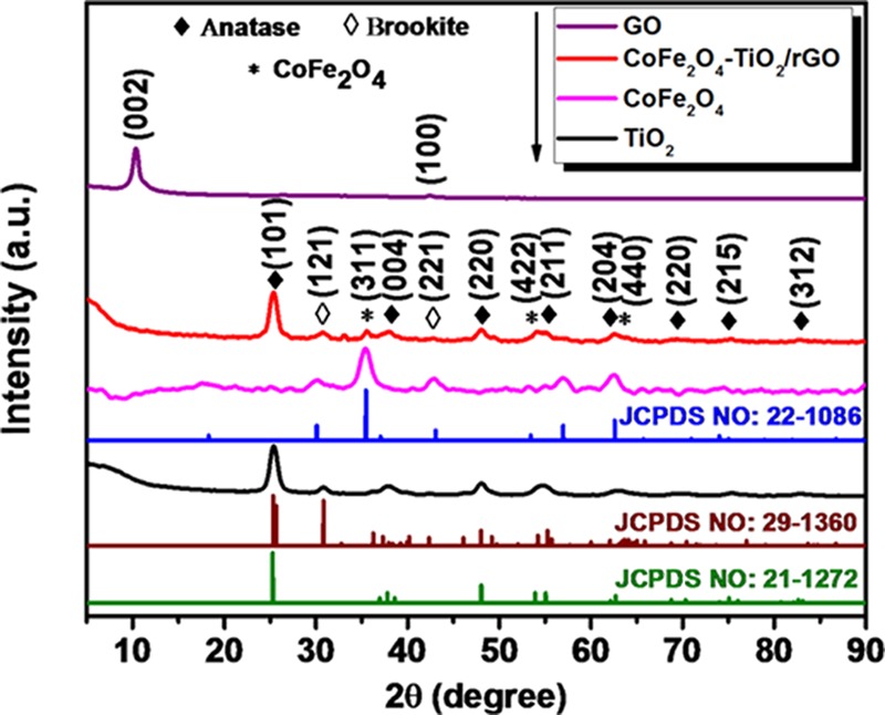
XRD patterns of GO, TiO2, CoFe2O4, and CoFe2O4–TiO2/rGO photocatalysts.
Figure 2 displays the Fourier transform infrared (FTIR) spectra of GO, CoFe2O4, TiO2, CoFe2O4–TiO2, and CoFe2O4–TiO2/rGO photocatalysts. GO exhibits the characteristic peak at 3432 cm–1, corresponding to the O–H stretching, whereas the peaks appearing at 1715, 1622, 1397, 1233, and 1057 cm–1 are related to the stretching vibration (C=O), aromatic carbon vibration (C=C), bending in carboxylic and carbonyl (O–H) groups, vibration of epoxy groups (C–O), and stretching vibration of alkoxy groups (C–O), respectively.40 For pristine TiO2, the IR peaks observed at 3432, 1626, and 1368 cm–1 can be ascribed to the stretching vibration mode of O–H and bonding modes of Ti–OH and Ti–O, respectively,41,42 whereas the broad band at 900–400 cm–1 is related to bulk titanate.43 CoFe2O4 NPs show two broad bands at 410 and 586 cm–1, which are assigned to the intrinsic stretching vibrations of the metal at the tetrahedral site and octahedral metal stretching, respectively.44,45 The broad band at 400–800 cm–1 observed for CoFe2O4–TiO2/rGO can be ascribed to the Ti–O–Ti, Ti–O-C, or Fe–O stretching vibrations. The peak intensities of GO functional groups are significantly less in CoFe2O4–TiO2/rGO photocatalysts, indicating the reduction of GO during calcination. In the FTIR spectra of the CoFe2O4–TiO2/rGO photocatalyst, all of the IR peaks of both CoFe2O4 and TiO2 are present, which are in accordance with the XRD and X-ray photoelectron spectroscopy (XPS) results.
Figure 2.
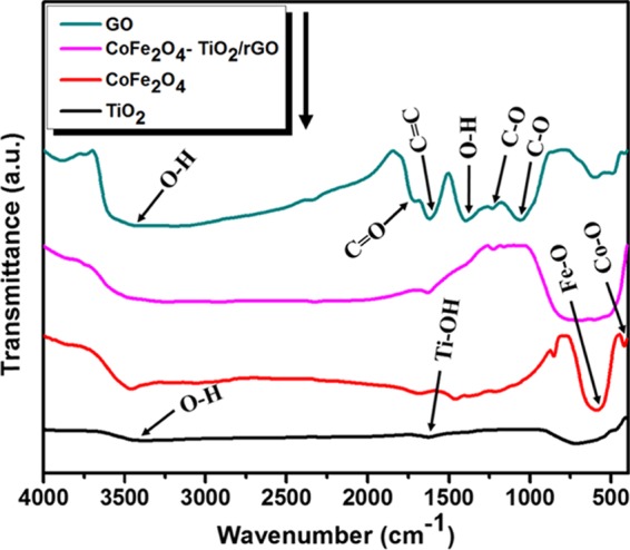
FTIR spectra of GO, TiO2, CoFe2O4, CoFe2O4–TiO2, and CoFe2O4–TiO2/rGO photocatalysts.
The Raman spectra of pristine TiO2, CoFe2O4–TiO2, and CoFe2O4–TiO2/rGO photocatalysts are displayed in Figure 3. Pure TiO2 shows Raman peaks at about 146, 403, 521, and 640 cm–1corresponding to the Eg(1), B1g, A1g + B1g(2), and Eg(2) modes of anatase, respectively, whereas the peaks at 247 and 321 cm–1 are related to the A1g and B1g modes of the brookite phase of TiO2.16 Additional Raman peaks appearing at 470 cm–1 (T1g(2)) and 624 cm–1 (A1g(2)) in the CoFe2O4–TiO2/rGO photocatalyst can be assigned to the symmetric stretching of the Fe–Co–O bond and the symmetric vibration mode of the metal in the octahedral and tetrahedral sides of CoFe2O4, respectively.46,47 The Raman peak intensities of TiO2 decreased in the CoFe2O4–TiO2/rGO photocatalyst, which can be due to the incorporation of CoFe2O4 and rGO into TiO2. As seen in Figure 3 (inset), the Eg(1) mode for CoFe2O4–TiO2 and CoFe2O4–TiO2/rGO photocatalysts is slightly shifted in comparison with the pristine TiO2, indicating the coupling of rGO and CoFe2O4 with TiO2. In the Raman spectra of the CoFe2O4–TiO2/rGO photocatalyst, two characteristic peaks of graphitic carbon (G-band) and disordered carbon (D-band) were observed at 1590 and 1298 cm–1, respectively. The ID/IG ratio of the CoFe2O4–TiO2/rGO photocatalyst is found to be 1.03, which is higher than that of GO (0.93), indicating effective reduction of GO during the thermal process.17
Figure 3.
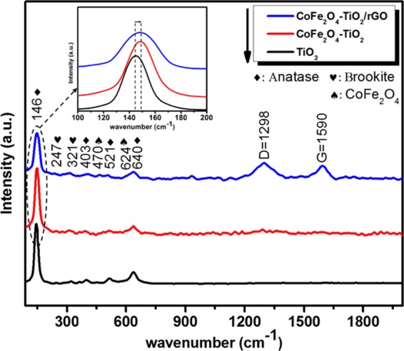
Raman spectra of TiO2, CoFe2O4–TiO2, and CoFe2O4–TiO2/rGO photocatalysts.
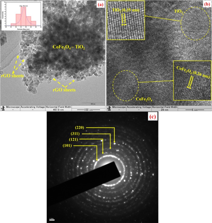
Figure S1a,b displays the scanning electron microscopy (SEM) images of the pure TiO2 and CoFe2O4–TiO2/rGO photocatalysts. As seen in Figure S1a,b, TiO2 exhibits irregular-shaped and agglomerated morphology and CoFe2O4 NPs are well dispersed on the surface of TiO2 NPs, respectively. The purity of the CoFe2O4–TiO2/rGO photocatalyst was verified by the energy-dispersive spectrometry (EDS) spectrum (Figure S1c), and the corresponding wt % results are shown in the table in the inset of Figure S1c. Figure 4 shows the transmission electron microscopy (TEM) images of the CoFe2O4–TiO2/rGO photocatalyst. As seen from the TEM image in Figure 4a, CoFe2O4–TiO2 photocatalysts are well dispersed and anchored on the rGO sheets with an average particle size of 35.2 nm as seen in the inset of Figure 4a. The high-resolution (HR)-TEM image of the CoFe2O4–TiO2/rGO photocatalysts is displayed in Figure 4b, which clearly discloses the interface formation between CoFe2O4 and TiO2. The lattice fringes with d-spacings of 0.35 and 0.26 nm correspond to the TiO2(101) and CoFe2O4(311) planes, respectively.34 The corresponding selected area electron diffraction (SAED) patterns of the CoFe2O4–TiO2/rGO photocatalyst are shown in Figure 4c. The diffraction rings could be ascribed to the (121) crystalline plane of brookite, the (101) and (220) planes of the anatase phase TiO2, and the (311) plane of cobalt ferrite. The SAED patterns further confirm the crystallinity of CoFe2O4–TiO2/rGO photocatalysts, which are in good accordance with the XRD patterns.
Figure 4.
(a) TEM image of the CoFe2O4–TiO2/rGO photocatalyst, (b) HR-TEM image of the CoFe2O4–TiO2/rGO photocatalyst, and (c) SAED pattern of the CoFe2O4–TiO2/rGO photocatalyst.
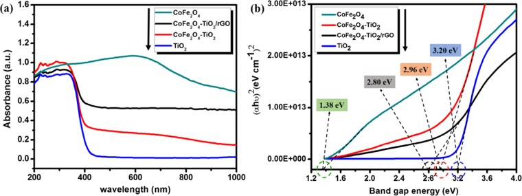
Figure 5 displays the absorption and the Tauc plots of the TiO2, CoFe2O4, CoFe2O4–TiO2, and CoFe2O4–TiO2/rGO photocatalysts.48 According to Figure 5a, the absorption band of the pristine TiO2 is at 388 nm, which corresponds to a band gap energy of 3.20 eV (Figure 5b), whereas CoFe2O4 with a black surface shows a broad absorption range from 200 to 1000 nm. After loading of 20 wt % CoFe2O4, the absorption edge of TiO2 is red-shifted from 388 to 419 nm with a band gap of 2.96 eV. Similarly, after incorporation 1 wt % rGO, the absorption edge further shifted to 443 nm, corresponding to a band gap of 2.80 eV. It is clear evidence that rGO not only is a solid support but also interacts chemically with the metal (Ti), thereby reducing the band gap energy of TiO2, which further enhances the charge carrier separation and transfer.49,50 The diffuse reflectance spectroscopy (DRS) results clearly show the incorporation of CoFe2O4 and rGO into TiO2 shifts the absorption intensity of TiO2 in the visible region by narrowing the band gap, which results from the formation of defect sites, such as Ti3+ and oxygen vacancies (Ov), addition of CoFe2O4 and Ti–C bond formation, thereby light absorbance increase, and more efficient utilization of light could be obtained, resulting in an increased photocatalytic performance of TiO2.49−51
Figure 5.
(a) UV–vis diffuse reflectance spectra and (b) Tauc plots of TiO2, CoFe2O4, CoFe2O4–TiO2, and CoFe2O4–TiO2/rGO photocatalysts.
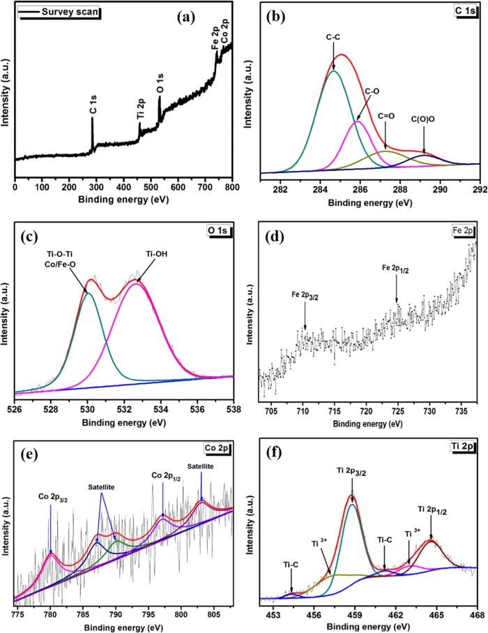
The chemical and electronic structures of the CoFe2O4–TiO2/rGO photocatalysts are examined by XPS. The peak signals for Fe, Co, O, C, and Ti are observed in the survey scan of the CoFe2O4–TiO2/rGO photocatalysts, as seen in Figure 6a. As shown in Figure 6b, C 1s displays four asymmetric peaks at 284.6, 285.8, 287.3, and 289.2 eV related to the aromatic ring (C=C/C–C), hydroxyl and epoxy groups (C–O), carbonyl groups (C=O), and carboxyl groups (C(O)O), respectively.52 The O 1s spectrum (Figure 6c) exhibits peaks at 530.4 and 532.7 eV related to the lattice oxygen in Ti–O–Ti and/or crystal lattice oxygen (oxygen bonded to the metal) in CoFe2O4 and oxygen in the Ti–OH bonds, respectively.53,54 Additionally, the Fe 2p spectrum (Figure 6d) shows two peaks, Fe 2p3/2 (710.2 eV) and Fe 2p1/2 (725.0 eV).55 The deconvolution of Co 2p is depicted in Figure 6e. The peaks at 797.0 and 780.1 eV are related to Co 2p1/2 and Co 2p3/2, respectively. The main Co 2p3/2 peak has two satellite peaks at 786.7 and 790.1 eV, which are ascribed to Co2+ in octahedral and tetrahedral sites, respectively. The intense Co 2p1/2 satellite peak at 803.0 eV confirms the presence of Co2+ species in the photocatalyst.56 The XPS spectrum of Ti 2p (Figure 6f) displays two peaks: Ti 2p3/2 (458.7 eV) and Ti 2p1/2 (464.6 eV).57 The peaks appearing at 457.3 and 463.0 eV correspond to the Ti 2p3/2 and Ti 2p1/2 peaks of Ti3+, indicating that Ti3+ species were formed as a result of the reaction of free carbon with oxygen in air on the surface of TiO2, which favors oxygen in the lattice of TiO2, resulting in the formation of oxygen vacancies (Ov) and the low valence state of Ti3+.49 Importantly, Ti3+ and Ov could act as an electron trapping center, which largely inhibit electron–hole pair recombination, resulting in enhanced photocatalytic activity. Notably, additional peaks appearing at 455.0 and 461.1 eV related to the Ti–C bond were observed, indicating the existence of chemical bonding between TiO2 and rGO sheets.58 The formation of Ti–C bond could also extend light absorption of TiO2 to the visible region.59 The XPS results further revealed the phase purity of the photocatalysts and bonding of rGO and TiO2 in the photocatalysts.
Figure 6.
(a) XPS spectra of the CoFe2O4–TiO2/rGO photocatalyst and the corresponding high-resolution XPS spectra of (b) C 1s (c) O 1s (d) Fe 2p (e) Co 2p, and (f) Ti 2p.
The photoluminescence (PL) spectra of pure TiO2, CoFe2O4–TiO2, CoFe2O4–TiO2/rGO photocatalysts are displayed in Figure 7. The PL emission spectra of bare TiO2 show several peaks at 417, 440, 447, and 465 nm. The observed peak at 417 nm is related to the band gap transition, whereas those at 440 and 447 nm are assigned to the defect sites including surface oxygen vacancies (Ov) and Ti3+ presence in TiO2 NPs.60−62 The peak at 465 nm is assigned to the free excitation emission of the band gap.60 After incorporating CoFe2O4 on the TiO2 surface, the PL emission intensity is significantly reduced, indicating lower charge carrier recombination. Furthermore, a significant PL quenching was observed when rGO was added to CoFe2O4–TiO2 photocatalysts. Indeed, the effect of rGO on the charge carrier separation was phenomenal and also revealed that rGO hindered or suppressed electron–hole pair recombination, which improved photocatalytic activity.49
Figure 7.
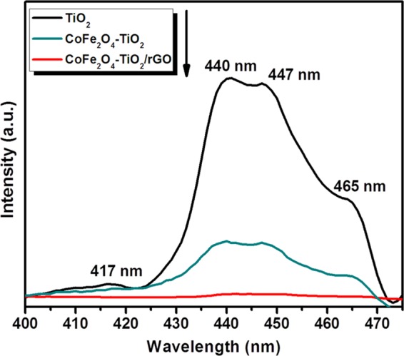
PL spectra of TiO2, CoFe2O4–TiO2, and CoFe2O4–TiO2/rGO photocatalysts.
The electrochemical impedance spectroscopy (EIS) is a promising method that is used to study the charge separation and transfer behavior of a photocatalyst.63 In general, a bigger arc radius of the Nyquist circle indicates a higher charge-transfer resistance. Figure S2 displays the Nyquist circle of TiO2, CoFe2O4–TiO2, and CoFe2O4–TiO2/rGO photocatalysts measured under simulated solar light irradiation. The larger arc radius for TiO2 suggests a higher charge-transfer resistance compared to that of CoFe2O4–TiO2 and CoFe2O4–TiO2/rGO photocatalysts. As shown in Figure S2, the CoFe2O4–TiO2/rGO ternary photocatalyst exhibited a smaller arc radius than that of CoFe2O4–TiO2.64,65 The results indicated that loading rGO significantly improved the electron mobility, thereby suppressing the charge-transfer resistance. This result is in accordance with the above PL results. Figure S3 shows the photocurrent study of TiO2, CoFe2O4–TiO2, and CoFe2O4–TiO2/rGO photocatalysts. The CoFe2O4–TiO2/rGO ternary photocatalyst gave higher photocurrent response compared to that of bare TiO2 and CoFe2O4–TiO2. This higher photocurrent response produced by the CoFe2O4–TiO2/rGO photocatalyst can be related to the high electron mobility of rGO at the interfaces of the CoFe2O4 and TiO2 heterojunction that greatly enhances migration and efficient charge carrier separation, which is in accordance with PL and EIS studies. These results are also consistent with the previous studies reported by Babu and Jiang et al.15,66
The magnetic separation performance of the prepared photocatalysts was further studied. Figure 8 displays the magnetic hysteresis loop of CoFe2O4 and CoFe2O4–TiO2/rGO photocatalysts, in which CoFe2O4 shows a symmetric hysteresis loop with a higher magnetization saturation value of ∼36.5 emu g–1 compared to that of the CoFe2O4–TiO2/rGO photocatalyst (∼5.9 emu g–1). This low magnetization saturation value is related to the presence of the nonmagnetic TiO2 and rGO. It still can be separated from the reaction solution using a simple magnet as seen in the inset of Figure 8. Furthermore, Figure 8 (inset) clearly reveals that the CoFe2O4–TiO2/rGO photocatalyst retains its magnetic separation performance after four consecutive cycles and can be a promising magnetic photocatalyst material. The above results demonstrated that the CoFe2O4–TiO2/rGO photocatalyst has good stability and recyclability during the photocatalytic reaction.
Figure 8.
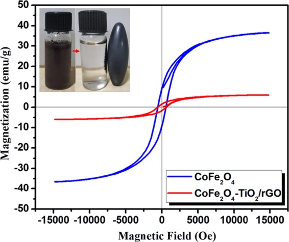
Magnetic hysteresis loop of CoFe2O4 and CoFe2O4–TiO2/rGO photocatalysts.
The photocatalytic H2 production activities of prepared photocatalysts were determined for water splitting under UV–vis light irradiation with glycerol as a hole scavenger. As depicted in Figure 9, the relative order of H2 production for the photocatalysts is P-25 TiO2 (methanol, 2772 μmol g–1 h–1) < P-25 TiO2 (glycerol, 4739 μmol g–1 h–1) < TiO2 (5336 μmol g–1 h–1) < rGO/TiO2 (9421 μmol g–1 h–1) < CoFe2O4–TiO2 (16 673 μmol g–1 h–1) < CoFe2O4–TiO2/rGO (76 559 μmol g–1 h–1). The photocatalytic H2 production rate achieved using present TiO2 NPs was 1.13 and 1.92 times higher than that of the commercially available TiO2 Degussa P-25 using glycerol and methanol, respectively. Moreover, the ternary CoFe2O4–TiO2/rGO photocatalyst exhibits almost 8-fold increment of H2 production activity compared to that of the binary TiO2/rGO photocatalyst (Figure 9). To understand the effects of CoFe2O4 loading on hydrogen production, different wt % of CoFe2O4 (10, 20, 30, and 40 wt %) were loaded onto TiO2, resulting in an increased H2 production activity till 20 wt %, which then decreases. The optimized sample (20 wt %) produced 16 673 μmol g–1 h–1 hydrogen (Figure 10), which is almost 3-fold higher than that from the bare TiO2. As shown in Figure 11, rGO plays a prominent role in boosting the H2 production activity of the as-prepared photocatalysts. After incorporation of different wt % of rGO (0.5, 1.0, 2.0, and 3.0 wt %) in the CoFe2O4–TiO2 photocatalyst, a further enhancement in the H2 evolution rate is observed (Figure 11). Surprisingly, a remarkable photocatalytic H2 production rate of 76 559 μmol g–1 h–1 is achieved with the optimized 1.0 wt % rGO in CoFe2O4–TiO2 that exceeds 14.4-folds higher than that of the bare TiO2. An apparent quantum yield of 12.97% at 400 nm was observed for the CoFe2O4–TiO2/rGO photocatalyst under optimized reaction conditions. This superior photocatalytic performance of the CoFe2O4–TiO2/rGO photocatalyst is associated with the existence of defect sites (Ti3+ and Ov), Ti–C bond formation, and effective formation of heterojunction between CoFe2O4 and TiO2, which efficiently facilitate the rapid interfacial charge transfer in the presence of rGO matrix.49,58 Furthermore, the photocatalytic H2 evolution achieved in the present study is significantly higher than already reported results, as depicted in Table S1. To determine the recyclability and durability of the optimized CoFe2O4–TiO2/rGO photocatalyst, four consecutive cycles of photocatalytic reaction were carried out. Each cycle was performed for 4 h under UV–visible irradiation. At the end of every cycle, the reactor solution was entirely wrapped with an aluminum foil and kept overnight in the dark. The reactor solution was evacuated, purged with N2 gas, and then placed on a magnetic stirrer under UV–visible irradiation for another reaction. A similar trend was followed up to four cycles. No significant loss of photocatalytic activity was observed for the CoFe2O4–TiO2/rGO photocatalyst up to four cycles, as shown in Figure 12. A minor decrease in the photocatalytic activity in the fourth cycle is observed, which can be attributed to a decrease of glycerol concentration in the solution because of the decomposition of glycerol.
Figure 9.
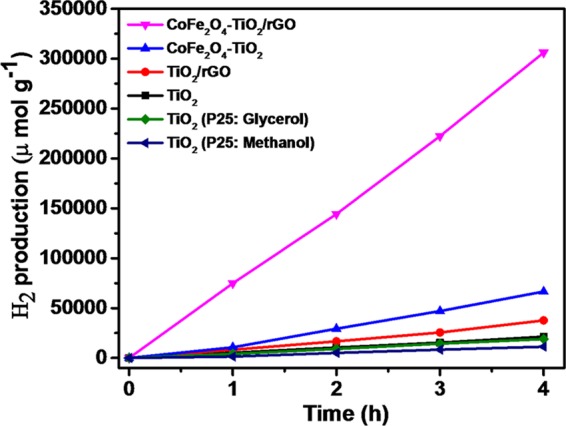
Photocatalytic H2 evolution of as-prepared TiO2, TiO2 (P25: Glycerol), TiO2 (P25: Methanol), rGO/TiO2, CoFe2O4–TiO2, and CoFe2O4–TiO2/rGO photocatalysts.
Figure 10.
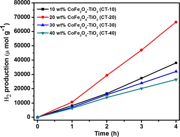
Photocatalytic H2 evolution of as-prepared 10 wt % CoFe2O4–TiO2 (CT-10), 20 wt % CoFe2O4–TiO2 (CT-20), 30 wt % CoFe2O4–TiO2 (CT-30), and 40 wt % CoFe2O4–TiO2 (CT-40) photocatalysts.
Figure 11.
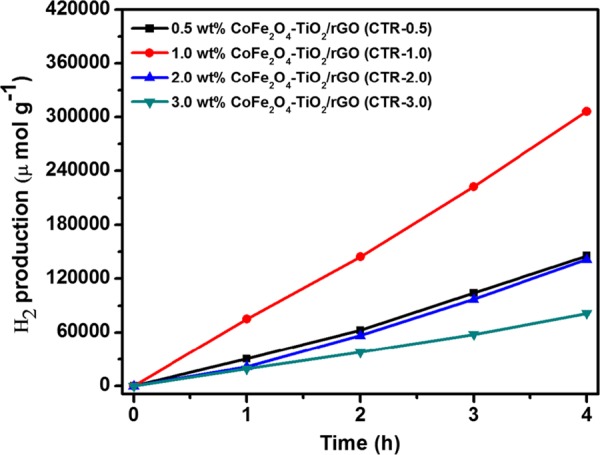
Photocatalytic H2 evolution of as-prepared 0.5 wt % CoFe2O4–TiO2/rGO (CTR-0.5), 1 wt % CoFe2O4–TiO2/rGO (CTR-1), 2 wt % CoFe2O4–TiO2/rGO (CTR-2), and 3 wt % CoFe2O4–TiO2/rGO (CTR-3) photocatalysts.
Figure 12.
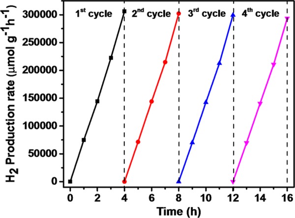
Reusability of the CoFe2O4–TiO2/rGO photocatalyst for four run cycles.
The improved photocatalytic performance of the as-prepared CoFe2O4–TiO2/rGO photocatalyst can be attributed to the combination of visible light sensitization, formation of a p–n heterojunction, presence of defect sites (Ti3+ and Ov), and synergistic effect of the rGO support layer. Based on the above results, it is undoubtedly proved that the formation of a p–n heterojunction, defect sites, and rGO support is the important factor to enhance the photocatalytic performance of the photocatalyst. The conduction band (ECB) and valence band (EVB) positions of the photocatalysts were computed theoretically by the following empirical formulas (eqs 1 and 2)67,68
| 1 |
| 2 |
where ECB and EVB represent the conduction and valence band potentials of a photocatalyst, respectively. χ is the electronegativity of the photocatalyst (the χ values for CoFe2O4 and TiO2 are 5.81 and 5.81 eV, respectively69,70), Ec represents the energy of free electrons on the hydrogen scale (∼4.5 eV), and Eg stands for the band-gap energy of the photocatalyst. Thus, the band-gap energies of TiO2 and CoFe2O4 were found to be 3.20 and 1.38 eV, respectively (Figure 5b). Table 1 shows the calculated values of EVB and ECB for CoFe2O4 and TiO2 using eqs 1 and 2, respectively.
Table 1. Electronegativity, Band Gap, and Conduction Band and Valance Band Positions of the Photocatalysts on NHE.
| photocatalyst | χ (eV) | Eg (eV) | ECB (eV) | EVB (eV) |
|---|---|---|---|---|
| CoFe2O4 | 5.81 | 1.38 | +0.62 | +2.00 |
| TiO2 | 5.81 | 3.20 | –0.29 | +2.91 |
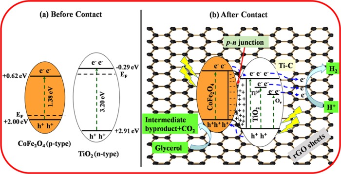
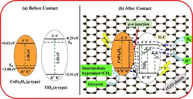
To understand the charge-transfer mechanism of TiO2 and CoFe2O4 over the rGO-supported photocatalyst, a plausible energy-level diagram for the CoFe2O4–TiO2/rGO photocatalyst system is constructed, as depicted in Figure 13. On the normal hydrogen electrode (NHE), the ECB edges of TiO2 and CoFe2O4 were calculated to be −0.29 and +0.62, respectively, and the corresponding EVB edges are at +2.91 and +2.00 eV, respectively (Table 1). The Fermi level (EF) of n-type TiO2 is below ECB, whereas that of p-type CoFe2O4 is above EVB.71 Before contact, the ECB position of TiO2 is higher than that of CoFe2O4 and the EF of TiO2 is above that of CoFe2O4, as depicted in Figure 13a. When these two photocatalysts are in contact, the EF of CoFe2O4 moves up, whereas the EF of TiO2 moves down, until the EF’s of TiO2 and CoFe2O4 get the same value. A p–n heterojunction is formed at the interface, and the electron transfer occurs from CoFe2O4 to TiO2 until it reached thermal equilibrium, resulting in the formation of the space charge region. The TiO2 and CoFe2O4 bands do bend, and the whole energy level of CoFe2O4 rises, whereas that of TiO2 descends.72,73 As a result, the ECB position of CoFe2O4 is higher than that of TiO2. Hence, the electrons can easily transfer from ECB of CoFe2O4 to ECB of TiO2 because of band bending. It was reported previously that the existence of Ti3+ and Ov induced new localized states below the CB of TiO2, which is responsible for the decrease of band gap of TiO2.74,75 The excess electrons accumulated in the ECB of TiO2 and the electrons present in the defect sites (Ti3+ and Ov) are mediated via the rGO surface and reduce protons (H+) to produce H2, as shown in Figure 13b.49,74 Therefore, the formed defect sites (Ti3+ and Ov) substantially suppress the charge carrier recombination rate and extend the visible light absorption, thereby enhancing the H2 production efficiency.76 The photogenerated holes can easily transfer from the higher EVB of TiO2 (+2.91 eV) to the lower EVB of CoFe2O4 (+2.00 eV), where they do react with glycerol to generate an intermediate product and CO2. Thus, this providential increase in hydrogen production performance can be related to the presence of defect sites (Ti3+ and Ov) and Ti–C bond formation, which efficiently extend the photoresponse of TiO2 to the visible region.
Figure 13.
Plausible mechanism of photocatalytic activity under UV–vis light irradiation of the CoFe2O4–TiO2/rGO photocatalyst.
3. Conclusions
In summary, a magnetic material CoFe2O4 and TiO2 photocatalysts along with reduced graphene oxide (rGO) as a support were prepared by a simple ultrasound-assisted wet impregnation method. A superior hydrogen production activity was achieved for the optimized magnetic material CoFe2O4 (20 wt %) and rGO (1 wt %) loaded on the TiO2 surface. The effect of rGO loading was phenomenal in the present study and exhibited maximum H2 production rate of 76 559 μmol g– h–1, which is ∼5- and ∼14-fold enhancement compared to that of CoFe2O4–TiO2 and the bare TiO2, respectively. This remarkable enhancement was related to the addition of CoFe2O4, presence of defect sites (Ti3+ and Ov), and strong interaction between rGO sheets and TiO2 through Ti–C bond formation, which were responsible for the synergistic effect. The XPS and PL studies undoubtedly proved the existence of defect sites (Ti3+ and Ov) and Ti–C bond in the CoFe2O4–TiO2/rGO photocatalysts. Furthermore, a substantial reduction in PL emission intensity and the high transient photocurrent response further supported high transfer efficiency and the charge carrier separation in the presence of rGO sheet, resulting in the superior photocatalytic activity. Moreover, the photocatalyst showed good stability and can easily be separated after the reaction using a simple magnet.
4. Experimental Details
4.1. Materials
Graphite powder (99.9995%) and cobalt nitrate hexahydrate and iron nitrate nonahydrate, citric acid, and graphite powder were procured from Alfa Aesar and Merck, India, respectively. Titanium tetraisopropoxide (TTIP) and commercially available solvents such as ethanol, methanol, and isopropanol were purchased from Sigma-Aldrich, SRL and Rankem, India, respectively.
4.2. Characterization Studies
The crystal phase of the as-synthesized photocatalysts was analyzed by X-ray diffraction (PANalytical X’pert powder diffractometer) using Cu Kα radiation (λ = 1.5406 Å). The morphologies of the photocatalysts were recorded on a transmission electron microscope (TEM, JEOL JEM 2100F, accelerating voltage of 200 kV). HR-TEM was used to record the size and shape of the as-synthesized photocatalysts. Field emission-scanning electron microscopy images were obtained using a FEI Quanta FEG 200 HR-SEM. UV–vis diffuse reflectance spectroscopy (DRS) measurements were performed with a Shimadzu UV-2600 UV–vis spectrophotometer in DRS mode. The chemical and elemental compositions of the photocatalyst were identified by X-ray photoelectron spectroscopy (XPS) using Al Kα instruments, as a source at 1350 eV. Fourier transform infrared (FTIR) spectroscopy was performed using a Perkin Elmer spectrometer. Raman spectra were examined by Bruker IFS 66V/FRA 106. Photoluminescence (PL) spectra of photocatalysts were analyzed by a JASCO FP-6300 fluorescence spectrometer.
4.3. Fabrication of the CoFe2O4–TiO2/rGO Photocatalyst
4.3.1. Synthesis of TiO2 NPs
In typical synthesis, TiO2 NPs were prepared as reported previously.16 Isopropanol (15 mL) and titanium tetraisopropoxide (5 mL) were slowly added into 250 mL of deionized (DI) water at pH ∼ 3, under vigorous stirring, respectively. A white precipitate was formed, which was stirred for another 2 h and then kept in the oven for 22 h at 60 °C. The precipitate was collected and centrifuged seven times with DI water. The resultant sample was dried overnight at 80 °C followed by calcination for 2 h at 400 °C. The photocatalyst was labeled as Ti.
4.3.2. Synthesis of CoFe2O4 NPs
CoFe2O4 NPs were prepared via the precipitation method.77 In a typical synthesis, Fe(NO3)3·9H2O (2.0 g) and Co(NO3)2·6H2O (0.73 g) were put into a glass beaker with 50 mL of deionized (DI) water. The mixture was dissolved after stirring for 10 min and, separately, citric acid (1.44 g) was dissolved in 50 mL of DI water. Then, the above solution was mixed and sonicated for 20 min followed by vigorous stirring for 3 h. The pH was maintained at 9 by adding dilute NaOH. A brown precipitate was formed, which was further stirred for 3 h at 80 °C. A dark brown gel was collected, which was centrifuged five times with DI water, dried overnight at 70 °C, and then calcined at 550 °C for 2 h. The photocatalyst was labeled as CF.
4.3.3. Synthesis of CoFe2O4–TiO2/rGO Photocatalysts
GO was prepared through a modified Hummer’s method as reported in a previous report.15 The CoFe2O4–TiO2/rGO photocatalyst was fabricated by the ultrasound-assisted wet impregnation method, as shown in Scheme 1. Different amounts of GO (0.5, 1.0, 2.0, and 3.0 wt %) were added to a beaker containing the ethanol–water mixture. Then, the solution was sonicated for 1 h followed by addition of TiO2 under stirring for 3 h. A different weight percentage of CoFe2O4 (10, 20, 30, and 40 wt %) was loaded onto the above solution under vigorous stirring for 4 h. Finally, the samples were washed five times with DI water and dried at 70 °C for 12 h, followed by calcination for 2 h at 400 °C. The samples were labeled as CTR-0.5, CTR-1, CTR-2, and CTR-3. The same trend was adopted to synthesize the CoFe2O4–TiO2 photocatalyst without GO, and the photocatalysts were labeled as CT-10, CT-20, CT-30, and CT-40.
Scheme 1.
4.4. Hydrogen Production Test
The photocatalytic H2 production experiment was carried out in a glass reactor (135 mL) closed with a rubber septum. A xenon lamp (250 W) was used as a light source. Then, 5.0 mg of photocatalyst was added into 50 mL of glycerol–water (5/45 v/v) solution. The mixture was magnetically stirred in the dark under N2 purging for 30 min to ensure adsorption–desorption equilibrium. Then, the sample solution was irradiated under the light source. The H2 gas produced was evaluated using a gas chromatograph (Shimadzu GC-2014; nitrogen as a carrier gas). The apparent quantum efficiency (AQY) of the prepared photocatalyst was calculated as shown in Section S1.
4.5. Photoelectrochemical Studies
All of the electrochemical measurements were performed in an electrochemical workstation (CHI608E) using the traditional three-electrode experimental system: glassy carbon electrode (area 0.385 mm2), Pt, and Ag/AgCl were utilized as the working, counter, and the reference electrodes, respectively. A 300 W xenon lamp (OSRAM, Germany) was employed as the source of light, and 0.5 M Na2SO4 aqueous solution as an electrolyte. Then, 2.5 mg of the photocatalyst was dispersed in 250 μL of ethanol and 5 μL of Nafion and then ultrasonicated for 1 h to form a slurry solution. The slurry was dip-coated onto a precleaned working electrode. After air-drying, the prepared photoelectrode was immersed in a 0.5 M Na2SO4 electrolyte solution.
Acknowledgments
The authors express sincere thanks to the Ministry of New and Renewable Energy (MNRE), New Delhi, India (103/239/2015-NT), and the Science and Engineering Research Board Department of Science and Technology (SERB-DST), New Delhi, India (EMR/2014/000645).
Supporting Information Available
The Supporting Information is available free of charge on the ACS Publications website at DOI: 10.1021/acsomega.8b03221.
Details on apparent quantum efficiency (AQY %) calculation, SEM and EDS images of the photocatalysts, EIS measurements and photocurrent studies of the prepared photocatalysts, and the comparison table of the photocatalytic H2 production activity with existing TiO2-based materials (PDF)
The authors declare no competing financial interest.
Supplementary Material
References
- Zeng D.; Xu W.; Ong W.-J.; Xu J.; Ren H.; Chen Y.; Zheng H.; Peng D.-L. Toward noble-metal-free visible-light-driven photocatalytic hydrogen evolution: Monodisperse sub-15 nm Ni2P nanoparticles anchored on porous g-C3N4 nanosheets to engineer 0D-2D heterojunction interfaces. Appl. Catal., B 2018, 221, 47–55. 10.1016/j.apcatb.2017.08.041. [DOI] [Google Scholar]
- Wang S.; Guan B. Y.; Wang X.; Lou X. W. D. Formation of Hierarchical Co9S8@ZnIn2S4 Heterostructured Cages as An Efficient Photocatalyst for Hydrogen Evolution. J. Am. Chem. Soc. 2018, 140, 15145–15148. 10.1021/jacs.8b07721. [DOI] [PubMed] [Google Scholar]
- Chen X.; Shen S.; Guo L.; Mao S. S. Semiconductor-based photocatalytic hydrogen generation. Chem. Rev. 2010, 110, 6503–6570. 10.1021/cr1001645. [DOI] [PubMed] [Google Scholar]
- Kudo A.; Miseki Y. Heterogeneous photocatalyst materials for water splitting. Chem. Soc. Rev. 2009, 38, 253–278. 10.1039/B800489G. [DOI] [PubMed] [Google Scholar]
- Liu H.; Zhu D.; Shi H.; Shao X. Fabrication of a Contamination-Free Interface between Graphene and TiO2 Single Crystals. ACS Omega 2016, 1, 168–176. 10.1021/acsomega.6b00074. [DOI] [PMC free article] [PubMed] [Google Scholar]
- Lu X.; Wang G.; Xie S.; Shi J.; Li W.; Tong Y.; Li Y. Efficient photocatalytic hydrogen evolution over hydrogenated ZnO nanorodarrays. Chem. Commun. 2012, 48, 7717–7719. 10.1039/c2cc31773g. [DOI] [PubMed] [Google Scholar]
- Li Y.; Hu Y.; Peng S.; Lu G.; Li S. Synthesis of CdS nanorods by an ethylenediamine assisted hydrothermal method for photocatalytic hydrogen evolution. J. Phys. Chem. C 2009, 113, 9352–9358. 10.1021/jp901505j. [DOI] [Google Scholar]
- Lin Z.; Wang X. Nanostructure Engineering and Doping of Conjugated Carbon Nitride Semiconductors for Hydrogen Photosynthesis. Angew. Chem., Int. Ed. 2013, 52, 1735–1738. 10.1002/anie.201209017. [DOI] [PubMed] [Google Scholar]
- Zhu T.; Wu H. B.; Wang Y.; Xu R.; Lou X. W. D. Formation of 1D Hierarchical Structures Composed of Ni3S2 Nanosheets on CNTs Backbone for Supercapacitors and Photocatalytic H2 Production. Adv. Energy Mater. 2012, 2, 1497–1502. 10.1002/aenm.201200269. [DOI] [Google Scholar]
- Quan Q.; Xie S.; Weng B.; Wang Y.; Xu Y.-J. Revealing the Double-Edged Sword Role of Graphene on Boosted Charge Transfer versus Active Site Control in TiO2 Nanotube Arrays@RGO/MoS2 Heterostructure. Small 2018, 1704531 10.1002/smll.201704531. [DOI] [PubMed] [Google Scholar]
- Xiang Q.; Yu J.; Jaroniec M. Graphene-based semiconductor photocatalysts. Chem. Soc. Rev. 2012, 41, 782–796. 10.1039/C1CS15172J. [DOI] [PubMed] [Google Scholar]
- Xiang Q.; Yu J.; Jaroniec M. Enhanced photocatalytic H2-production activity of graphene-modified titania nanosheets. Nanoscale 2011, 3, 3670. 10.1039/c1nr10610d. [DOI] [PubMed] [Google Scholar]
- Wu M.; Gu L.; Wang Q.; Wang C.; Zhang H. Interfacial assembly of robust TiO2 nanosheets onto silica-modified reduced graphene oxide for high-efficient degradation of organic dyes. ChemNanoMat 2018, 4, 387–393. 10.1002/cnma.201700369. [DOI] [Google Scholar]
- Bian S.; Zhou C.; Li P.; Liu J.; Dong X.; Xi F. Graphene quantum dots decorated titania nanosheets heterojunction: efficient charge separation and enhanced visible light photocatalytic performance. ChemCatChem 2017, 9, 3349–3357. 10.1002/cctc.201601594. [DOI] [Google Scholar]
- Babu S. G.; Vinoth R.; Kumar D. P.; Shankar M. V.; Chou H. L.; Vinodgopal K.; Neppolian B. Influence of electron storing, transferring and shuttling assets of reduced graphene oxide at the interfacial copper doped TiO2 p–n heterojunction for increased hydrogen production. Nanoscale 2015, 7, 7849–7857. 10.1039/C5NR00504C. [DOI] [PubMed] [Google Scholar]
- Hafeez H. Y.; Lakhera S. K.; Bellamkonda S.; Rao G. R.; Shankar M. V.; Bahnemann D. W.; Neppolian B. Construction of ternary hybrid layered reduced graphene oxide supported g-C3N4-TiO2 nanocomposite and its photocatalytic hydrogen production activity. Int. J. Hydrogen Energy 2018, 43, 3892–3904. 10.1016/j.ijhydene.2017.09.048. [DOI] [Google Scholar]
- Vinoth R.; Karthik P.; Muthamizhchelvan C.; Neppolian B.; Ashokkumar M. Carrier separation and charge transport characteristics of reduced graphene oxide supported visible-light active photocatalysts. Phys. Chem. Chem. Phys. 2016, 18, 5179–5191. 10.1039/C5CP08041J. [DOI] [PubMed] [Google Scholar]
- Bellamkonda S.; Thangavel N.; Hafeez H. Y.; Neppolian B.; Rao G. R. Highly active and stable multi-walled carbon nanotubes-graphene-TiO2 nanohybrid: An efficient non-noble metal photocatalyst for water splitting. Catal. Today 2019, 321–322, 120–127. 10.1016/j.cattod.2017.10.023. [DOI] [Google Scholar]
- Hafeez H. Y.; Lakhera S. K.; Karthik P.; Anpo M.; Neppolian B. Facile construction of ternary CuFe2O4-TiO2 nanocomposite supported reduced graphene oxide (rGO) photocatalysts for the efficient Hydrogen production. Appl. Surf. Sci. 2018, 449, 772–779. 10.1016/j.apsusc.2018.01.282. [DOI] [Google Scholar]
- Kumar D. P.; Reddy N. L.; Karthik M.; Neppolian B.; Madhavan J.; Shankar M. V. Cu2O-sensitized TiO2 nanorods with nano cavities for highly efficient photocatalytic hydrogen production under solar irradiation. Sol. Energy Mater. Sol. Cells 2016, 154, 78–87. 10.1016/j.solmat.2016.04.033. [DOI] [Google Scholar]
- Ghosh B. K.; Moitra D.; Chandel M.; Ghosh N. N. Preparation of TiO2/Cobalt Ferrite/Reduced Graphene Oxide Nanocomposite Based Magnetically Separable Catalyst with Improved Photocatalytic Activity. J. Nanosci. Nanotechnol. 2017, 17, 4694–4703. 10.1166/jnn.2017.13740. [DOI] [Google Scholar]
- Huang S.; Xu Y.; Xie M.; Xu H.; He M.; Xia J.; Huang L.; Li H. Synthesis of magnetic CoFe2O4/g-C3N4 composite and its enhancement of photocatalytic ability under visible-light. Colloids Surf., A 2015, 478, 71–80. 10.1016/j.colsurfa.2015.03.035. [DOI] [Google Scholar]
- Li N. W.; Zheng M. B.; Chang X. F.; Ji G. B.; Lu H. L.; Xue L. P.; Pan L. J.; Cao J. M. Preparation of magnetic CoFe2O4-functionalized graphene sheets via a facile hydrothermal method and their adsorption properties. J. Solid State Chem. 2011, 184, 953–958. 10.1016/j.jssc.2011.01.014. [DOI] [Google Scholar]
- Chang C. J.; Lee Z.; Chu K. W.; Wei Y. H. CoFe2O4@ZnS core–shell spheres as magnetically recyclable photocatalysts for hydrogen production. J. Taiwan Inst. Chem. Eng. 2016, 66, 386–393. 10.1016/j.jtice.2016.06.033. [DOI] [Google Scholar]
- Chen J.; Zhao D.; Diao Z.; Wang M.; Shen S. Ferrite boosting photocatalytic hydrogen evolution over graphitic carbon nitride: a case study of (Co, Ni)Fe2O4 modification. Sci. Bull. 2016, 61, 292–301. 10.1007/s11434-016-0995-0. [DOI] [Google Scholar]
- Haw C.; Chiu W.; Rahman S. A.; Khiew P.; Radiman S.; Shukor R. A.; Hamid M. A. A.; Ghazali N. The design of new magnetic-photocatalyst nanocomposites (CoFe2O4–TiO2) as smart nanomaterials for recyclable-photocatalysis applications. New J. Chem. 2016, 40, 1124–1136. 10.1039/C5NJ02496J. [DOI] [Google Scholar]
- He G.; Ding J.; Zhang J.; Hao Q.; Chen H. One-Step Ball-Milling Preparation of Highly Photocatalytic Active CoFe2O4–Reduced Graphene Oxide Heterojunctions for Organic Dye Removal. Ind. Eng. Chem. Res. 2015, 54, 2862–2867. 10.1021/ie504706w. [DOI] [Google Scholar]
- Alamelu K.; Raja V.; Shiamala L.; Ali B. M. J. Biphasic TiO2 nanoparticles decorated grapheme nanosheets for visible light driven photocatalytic degradation of organic dyes. Appl. Surf. Sci. 2018, 430, 145–154. 10.1016/j.apsusc.2017.05.054. [DOI] [Google Scholar]
- Wen L.; Spyridon Z. A Brief Review of the Synthesis and Catalytic Applications of Graphene-Coated Oxides. ChemCatChem 2017, 9, 2432–2442. 10.1002/cctc.201700178. [DOI] [Google Scholar]
- Park S.; Ruoff R. S. Chemical methods for the production of graphenes. Nat. Nanotechnol. 2009, 4, 217–224. 10.1038/nnano.2009.58. [DOI] [PubMed] [Google Scholar]
- Park J.; Jin T.; Liu C.; Li G.; Yan M. Three-Dimensional Graphene-TiO2 Nanocomposite Photocatalyst Synthesized by Covalent Attachment. ACS Omega 2016, 1, 351–356. 10.1021/acsomega.6b00113. [DOI] [PMC free article] [PubMed] [Google Scholar]
- Chua C. K.; Pumera M. Chemical Reduction of Graphene Oxide: a Synthetic Chemistry Viewpoint. Chem. Soc. Rev. 2014, 43, 291–312. 10.1039/C3CS60303B. [DOI] [PubMed] [Google Scholar]
- Xiang Q.; Yu J.; Jaroniec M. Synergetic effect of MoS2 and graphene as cocatalysts for enhanced photocatalytic H2 production activity of TiO2 nanoparticles. J. Am. Chem. Soc. 2012, 134, 6575–6578. 10.1021/ja302846n. [DOI] [PubMed] [Google Scholar]
- Chen D.; Zou L.; Li S.; Zheng F. Nanospherical like reduced graphene oxide decorated TiO2 nanoparticles: an advanced catalyst for the hydrogen evolution reaction. Sci. Rep. 2016, 6, 20335 10.1038/srep20335. [DOI] [PMC free article] [PubMed] [Google Scholar]
- Gupta V. K.; Eren T.; Atar N.; Yola M. L.; Parlak C.; Karimi-Maleh H. CoFe2O4@TiO2 decorated reduced graphene oxide nanocomposite for photocatalytic degradation of chlorpyrifos. J. Mol. Liq. 2015, 208, 122–129. 10.1016/j.molliq.2015.04.032. [DOI] [Google Scholar]
- Niu Y.; Huang X.; Zhao L.; Hu W.; Li C. M. One-Pot Synthesis of Co/CoFe2O4 Nanoparticles Supported on N-Doped Graphene for Efficient Bifunctional Oxygen Electrocatalysis. ACS Sustainable Chem. Eng. 2018, 6, 3556–3564. 10.1021/acssuschemeng.7b03888. [DOI] [Google Scholar]
- Neppolian B.; Wang Q.; Yamashita H.; Choi H. Synthesis and characterization of ZrO2-TiO2 binary oxide semiconductor nanoparticles: application and interparticle electron transfer process. Appl. Catal., A 2007, 333, 264–271. 10.1016/j.apcata.2007.09.026. [DOI] [Google Scholar]
- An X.; Hu C.; Liu H.; Qu J. Oxygen vacancy mediated construction of anatase/brookite heterophase junctions for high-efficiency photocatalytic hydrogen evolution. J. Mater. Chem. A 2017, 5, 24989–24994. 10.1039/C7TA08809D. [DOI] [Google Scholar]
- Yang M. Q.; Zhang N.; Xu Y. J. Synthesis of Fullerene-, Carbon Nanotube-, and Graphene-TiO2 Nanocomposite Photocatalysts for Selective Oxidation: A Comparative Study. ACS Appl. Mater. Interfaces 2013, 5, 1156–1164. 10.1021/am3029798. [DOI] [PubMed] [Google Scholar]
- Bose S.; Kuila T.; Uddin M. E.; Kim N. H.; Lau A. K. T.; Lee J. H. In-situ synthesis and characterization of electrically conductive polypyrrole/graphene nanocomposites. Polymer 2010, 51, 5921–5928. 10.1016/j.polymer.2010.10.014. [DOI] [Google Scholar]
- Abazović N. D.; Čomor M. I.; Dramićanin M. D.; Jovanović D. J.; Ahrenkiel S. P.; Nedeljković J. M. Photoluminescence of Anatase and Rutile TiO2 Particles. J. Phys. Chem. B 2006, 110, 25366–25370. 10.1021/jp064454f. [DOI] [PubMed] [Google Scholar]
- Mugundan S.; Rajamannan B.; Viruthagiri G.; Shanmugam N.; Gobi R.; Praveen P. Synthesis and characterization of undoped and cobalt-doped TiO2 nanoparticles via sol-gel technique. Appl. Nanosci. 2015, 5, 449–456. 10.1007/s13204-014-0337-y. [DOI] [Google Scholar]
- Kumar P. M.; Badrinarayanan S.; Sastry M. Nanocrystalline TiO2 studied by optical, FTIR and X-ray photoelectron spectroscopy: correlation to presence of surface states. Thin Solid Films 2000, 358, 122–130. 10.1016/S0040-6090(99)00722-1. [DOI] [Google Scholar]
- Baykal A.; Kasapoğlu N.; Köseoğlu Y.; Başaran A.; Kavas H.; Toprak M. Microwave-induced combustion synthesis and characterization of NixCo1–xFe2O4nanocrystals (x = 0.0, 0.4, 0.6, 0.8, 1.0). Cent. Eur. J. Chem. 2008, 6, 125–130. 10.2478/s11532-007-0070-4. [DOI] [Google Scholar]
- Patil S. A.; Mahajan V. C.; Ghatage A. K.; Lotke S. D. Structure and magnetic properties of Cd and Ti/Si substituted cobalt ferrites. Mater. Chem. Phys. 1998, 57, 86–92. 10.1016/S0254-0584(98)00202-8. [DOI] [Google Scholar]
- Ayyappan S.; Mahadevan S.; Chandramohan P.; Srinivasan M. P.; Philip J.; Raj B. Influence of Co2+ Ion Concentration on the Size, Magnetic Properties, and Purity of CoFe2O4 Spinel Ferrite Nanoparticles. J. Phys. Chem. C 2010, 114, 6334–6341. 10.1021/jp911966p. [DOI] [Google Scholar]
- Shemer G.; Tirosh E.; Livneh T.; Markovich G. Tuning a Colloidal Synthesis to Control Co2+ Doping in Ferrite Nanocrystals. J. Phys. Chem. C 2007, 111, 14334–14338. 10.1021/jp0736793. [DOI] [Google Scholar]
- Yan X.; Wang X.; Gu W.; Wu M.; et al. Single 4 crystalline AgIn(MoO4)2 Nanosheets Grafted Ag/AgBr Composites with Enhanced Plasmonic Photocatalytic Activity for Degradation of Tetracycline under Visible Light. Appl. Catal., B 2015, 164, 297–304. 10.1016/j.apcatb.2014.09.046. [DOI] [Google Scholar]
- Zhang Q.; Bao B.; Wang X.; Hu X.; Miao X.; Chaker M.; Ma D. Advanced fabrication of Chemically Bonded Graphene/TiO2 continuous Fibers with Enhanced Broadband Photocatalytic Properties and Involved Mechanisms Exploration. Sci. Rep. 2016, 6, 38066 10.1038/srep38066. [DOI] [PMC free article] [PubMed] [Google Scholar]
- Zhang H.; Lv X.; Li Y.; Wang Y.; Li J. P25-Graphene Composite as a High Performance Photocatalyst. ACS Nano 2010, 4, 380–386. 10.1021/nn901221k. [DOI] [PubMed] [Google Scholar]
- Zhang Y.; Pan C. TiO2/graphene composite from thermal reaction of graphene oxide and its photocatalytic activity in visible light. J. Mater. Sci. 2011, 46, 2622–2626. 10.1007/s10853-010-5116-x. [DOI] [Google Scholar]
- Dreyer D. R.; Park S.; Bielawski C. W.; Ruoff R. S. The chemistry of graphene oxide. Chem. Soc. Rev. 2010, 39, 228–240. 10.1039/B917103G. [DOI] [PubMed] [Google Scholar]
- Bian W. Y.; Yang Z. R.; Strasser P.; Yang R. Z. A CoFe2O4/graphene nanohybrid as an efficient bi-functional electrocatalyst for oxygen reduction and oxygen evolution. J. Power Sources 2014, 250, 196–203. 10.1016/j.jpowsour.2013.11.024. [DOI] [Google Scholar]
- Luciu I.; Bartali R.; Laidani N. Influence of hydrogen addition to an Ar plasma on the structural properties of TiO2–x thin films deposited by RF sputtering. J. Phys. D: Appl. Phys. 2012, 45, 345302 10.1088/0022-3727/45/34/345302. [DOI] [Google Scholar]
- Yamashita T.; Hayes P. Analysis of XPS spectra of Fe2+ and Fe3+ ions in oxide materials. Appl. Surf. Sci. 2008, 254, 2441–2449. 10.1016/j.apsusc.2007.09.063. [DOI] [Google Scholar]
- Zong M.; Huang Y.; Zhang N. Reduced graphene oxide-CoFe2O4 composite: Synthesis and electromagnetic absorption properties. Appl. Surf. Sci. 2015, 345, 272–278. 10.1016/j.apsusc.2015.03.203. [DOI] [Google Scholar]
- Chai B. B.; Peng T. Y.; Zeng P.; Mao J. Synthesis of floriated In2S3 decorated with TiO2nanoparticles for efficient photocatalytic hydrogen production under visible light. J. Mater. Chem. 2011, 21, 14587–14593. 10.1039/c1jm11566a. [DOI] [Google Scholar]
- Huang Q.; Tian S.; Zeng D.; Wang X.; Song W.; Li Y.; Xiao W.; Xie C. Enhanced photocatalytic activity of chemically bonded TiO2/Graphene composites based on the effective interfacial charge transfer through the C–Ti bond. ACS Catal. 2013, 3, 1477–1485. 10.1021/cs400080w. [DOI] [Google Scholar]
- Zhao D.; Sheng G.; Chen C.; Wang X. Enhanced photocatalytic degradation of methylene blue under visible irradiation on graphene@TiO2 dyade structure. Appl. Catal., B 2012, 111–112, 303–308. 10.1016/j.apcatb.2011.10.012. [DOI] [Google Scholar]
- Liu B.; Wang X.; Cai G.; Wen L.; Song Y.; Zhao X. Low temperature fabrication of Vdoped TiO2 nanoparticles, structure and photocatalytic studies. J. Hazard. Mater. 2009, 169, 1112–1118. 10.1016/j.jhazmat.2009.04.068. [DOI] [PubMed] [Google Scholar]
- Chen S. F.; Li J. P.; Qian K.; Xu W. P.; Lu Y.; Huang W. X.; Yu S. H. Large scale photochemical synthesis of M@TiO2 nanocomposites (M = Ag, Pd, Au, Pt) and their optical properties, CO oxidation performance, and antibacterial effect. Nano Res. 2010, 3, 244–255. 10.1007/s12274-010-1027-z. [DOI] [Google Scholar]
- Zhu P.; Nair A. S.; Shengjie P.; Shengyuan Y.; Ramakrishna S. Facile Fabrication of TiO2–Graphene composite with enhanced photovoltaic and photocatalytic properties by Electrospinning. ACS Appl. Mater. Interfaces 2012, 4, 581–585. 10.1021/am201448p. [DOI] [PubMed] [Google Scholar]
- Banerjee S.; Mohapatra S. K.; Das P. P.; Misra M. Synthesis of Coupled Semiconductor by Filling 1D TiO2 Nanotubes with CdS. Chem. Mater. 2008, 20, 6784–6791. 10.1021/cm802282t. [DOI] [Google Scholar]
- Wang S.; Guan B. Y.; Lou X. W. Construction of ZnIn2S4-In2O3 Hierarchical Tubular Heterostructures for Efficient CO2 Photoreduction. J. Am. Chem. Soc. 2018, 140, 5037–5040. 10.1021/jacs.8b02200. [DOI] [PubMed] [Google Scholar]
- Jiang Q.; Sun L.; Bi J.; Liang S.; Li L.; Yu Y.; Wu L. MoS2 quantum dots modified covalent triazine-based frameworks for enhanced photocatalytic hydrogen evolution. ChemSusChem 2018, 11, 1108–1113. 10.1002/cssc.201702220. [DOI] [PubMed] [Google Scholar]
- Wang M.; Liu Q.; Xu N.; Su N.; Wang X.; Su W. An amorphous CoSx modified Mn0.5Cd0.5S solid solution with enhanced visible-light photocatalytic H2-production activity. Catal. Sci. Technol. 2018, 8, 4122–4128. 10.1039/C8CY01253A. [DOI] [Google Scholar]
- Lakhera S. K.; Watts A.; Hafeez H. Y.; Neppolian B. Interparticle double charge transfer mechanism of heterojunction α-Fe2O3/Cu2Omixed oxide catalysts and its visible light photocatalytic activity. Catal. Today 2018, 300, 58–70. 10.1016/j.cattod.2017.03.020. [DOI] [Google Scholar]
- Lakhera S. K.; Hafeez H. Y.; Veluswamy P.; Ganesh V.; Khan A.; Ikeda H.; Neppolian B. Enhanced photocatalytic degradation and hydrogen production activity of in situ grown TiO2 coupled NiTiO3 nanocomposites. Appl. Surf. Sci. 2018, 449, 790–798. 10.1016/j.apsusc.2018.02.136. [DOI] [Google Scholar]
- Xu Y.; Schoonen M. A. A. The absolute energy positions of conduction and valence bands of selected semiconducting minerals. Am. Mineral. 2000, 85, 543–556. 10.2138/am-2000-0416. [DOI] [Google Scholar]
- Zhang L.; Zhang A.; Lu H.; Sun Z.; Sheng W.; Sun L.; Xiang J. Magnetically separable AgI–BiOI/CoFe2O4 hybrid composites for HgO removal: characterization, activity and mechanism. RSC Adv. 2017, 7, 31448–31456. 10.1039/C7RA04175F. [DOI] [Google Scholar]
- Zhang Y.; Schultz A. M.; Salvador P. A.; Rohrer G. S. Spatially selective visible light photocatalytic activity of TiO2/BiFeO3 heterostructures. J. Mater. Chem. 2011, 21, 4168–4174. 10.1039/c0jm04313c. [DOI] [Google Scholar]
- Humayun M.; Zada A.; Li Z.; Xie M.; Zhang X.; Qu Y.; Raziq F.; Jing L. Enhanced visible-light activities of porous BiFeO3 by coupling with nanocrystalline TiO2 and mechanism. Appl. Catal., B 2016, 180, 219–226. 10.1016/j.apcatb.2015.06.035. [DOI] [Google Scholar]
- Xiang Y.; Ju P.; Wang Y.; Sun Y.; Zhang D.; Yu J. Chemical etching preparation of the Bi2WO6/BiOI p–n heterojunction with enhanced photocatalytic antifouling activity under visible light irradiation. Chem. Eng. J. 2016, 288, 264–275. 10.1016/j.cej.2015.11.103. [DOI] [Google Scholar]
- Qiu B.; Zhou Y.; Ma Y.; Yang X.; Sheng W.; Xing M.; Zhang J. Facile synthesis of the Ti3+ self-doped TiO2-graphene nanosheet composites with enhanced photocatalysis. Sci. Rep. 2015, 5, 8591 10.1038/srep08591. [DOI] [PMC free article] [PubMed] [Google Scholar]
- Zuo F.; Bozhilov K.; Dillon R. J.; Wang L.; Smith P.; Zhao X.; Bardeen C.; Feng P. Active facets on Titanium (III)-Doped TiO2: An effective strategy to improve the visible-light photocatalytic Activity. Angew. Chem. 2012, 124, 6327–6330. 10.1002/ange.201202191. [DOI] [PubMed] [Google Scholar]
- Karthik P.; Balaraman E.; Neppolian B. Efficient solar light driven H2 production: A post-synthetic encapsulation of Cu2O co-catalyst on metal-organic framework (MOF) for boosting the effective charge-carrier separation. Catal. Sci. Technol. 2018, 8, 3286–3294. 10.1039/C8CY00604K. [DOI] [Google Scholar]
- Sivagurunathan P.; Gibin S. R. Preparation and characterization of nanosized cobalt ferrite particles by co-precipitation method with citrate as chelating agent. J. Mater. Sci.: Mater. Electron. 2016, 27, 8891–8898. 10.1007/s10854-016-4915-5. [DOI] [Google Scholar]
Associated Data
This section collects any data citations, data availability statements, or supplementary materials included in this article.


