Abstract
The Beckmann rearrangement of oximes to amides typically requires strong acids or highly reactive, hazardous electrophiles and/or elevated temperatures to proceed. A very attractive alternative is the in situ generation of Vilsmeier–Haack reagents, by means of photoredox catalysis, as promoters for the thermal Beckmann rearrangement. Investigation of the reaction parameters for this light‐induced method using a one‐pot strategy has shown that the reaction is limited by the different temperatures required for each of the two sequential steps. Using a continuous flow reactor, the photochemical and thermal processes have been separated by integrating a flow photoreactor unit at low temperature for the electrophile generation with a second reactor unit, at high temperature, where the rearrangement takes place. This strategy has enabled excellent conversions and yields for a diverse set of oximes, minimizing the formation of side products obtained with the original one‐pot method.
Keywords: Beckmann rearrangement, Vilsmeier–Haack reagent, Photoredox catalysis, Chemical generator, Continuous flow
Introduction
The Beckmann rearrangement is an important and useful reaction in organic synthesis that entails the conversion of ketoximes to secondary amides. Since its discovery in 1886 by E. O. Beckmann,1 this transformation has found widespread application in the synthesis of natural products2 and the preparation of drug molecules,3 enabling the generation of amide scaffolds in the target compounds4 An important industrial application of the Beckmann rearrangement is the production of Nylon monomers.5
The accepted mechanism of the Beckmann rearrangement (Scheme 1) involves migration of one of the imine C‐substituents to the nitrogen atom, and it is believed to be driven by the release of the activated hydroxy group of the oxime (1). Strong protic acids,6 inorganic Lewis acids,7 acyl chlorides,2 acidic organic chlorides8 and other electrophilic reagents9 (E+) have been employed as mediators for the activation of the OH group by forming a complex or an ester (3) (Scheme 1), which then undergoes an exothermic rearrangement upon heating. Recent studies have revealed that the mechanism can be self‐propagative (Scheme 2a).10 Thus, the nitrilium cation 4 (the initial intermediate of the rearrangement) can activate another molecule of oxime via the complex 3A, which releases amide 2 and another nitrilium ion to start a new turnover. This mechanism only requires sub‐stoichiometric amounts of electrophilic mediator to initiate the reaction. Alternatively, when a tertiary amide (e.g., DMF11, 12 or NMP13) is used as solvent and combined with an acid chloride, the Vilsmeier–Haack (V‐H) reagent 5 generated in situ is responsible for the OH‐activation (Scheme 2b), via the intermediate 3B. As the V–H reagent is converted into the initial tertiary amide after the rearrangement, the reaction is no longer self‐propagative. The reaction time can be relatively fast (< 1 h) at ambient temperature,12, 13 although stoichiometric amounts of acid chloride are used to regenerate the V–H reagent.
Scheme 1.

General mechanism for the Beckmann rearrangement.
Scheme 2.
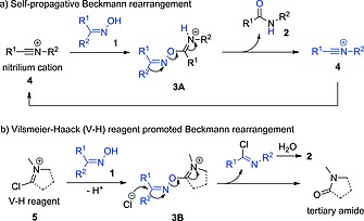
Activation of oxime hydroxy group in self‐propagative (a) and Vilsmeier–Haack reagent promoted (b) Beckmann rearrangements.
Apart from the well‐established methods mentioned above, many endeavors have been devoted to achieving Beckmann rearrangements under more benign and controllable conditions. These procedures include the use of boronic acid catalysts14 or radical pathways induced by (NH4)2S2O8/DMSO.15 Several examples of photochemical Beckmann rearrangements were reported in the 1960s and 1970s using UV‐C irradiation.16 Poor yields and selectivities were described, probably due to decomposition of the starting materials and/or products under the relatively harsh conditions utilized. An attractive alternative to avoid the drawbacks of UV light irradiation is a visible light promoted Beckmann rearrangement,17 in which the reaction is promoted by a V–H reagent generated from CBr4 and DMF by means of photoredox catalysis.18 This synthetic strategy permits the generation of the reactive V–H reagent under mild conditions, and avoids the use of toxic or corrosive reagents such as POCl3, SOCl2, COCl2 or tBuCOCl.11, 12, 13 Indeed, visible light induced V–H reagent generation and its application for the dehydration of aldoximes,19 the preparation of carboxylic acid anhydrides,20 Lossen rearrangement,21 Appel reaction18 and carbonylations22 have been recently reported.
The visible light promoted Beckmann rearrangement appears to be a promising protocol for the conversion of ketoximes to amides under mild condition. However, a one‐pot procedure in which the V–H reagent is photochemically generated and then promotes the thermal rearrangement can be considered as suboptimal, often leading to unsatisfactory results (vide infra). The two sequential processes taking place during the reaction (photochemical vs. thermal transformation) require different reaction conditions for optimal results. With this in mind, we envisaged a continuous flow strategy in which the active V–H reagent is photochemically generated and then consumed under different reaction conditions, by integrating the flow photoreactor with a second reactor unit (Scheme 3). Thus, CBr4 and a photocatalyst in DMF were pumped through a continuous flow photochemical reactor. The V–H reagent solution generated was immediately mixed with a second reaction stream containing the oxime substrate before entering a second reactor unit, in which the Beckmann rearrangement took place in the absence of light. Using this strategy, the sequential photochemical and thermal processes could be spatially separated and operated independently, leading to excellent results. Indeed, while the V–H reagent promoted Beckmann rearrangement required mild heating, the photochemical reagent generation performed best at low temperatures. The photochemical step, in addition, benefited from the intense and uniform light irradiation achievable in a microreactor.23, 24
Scheme 3.
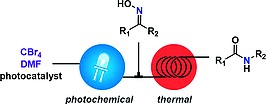
Concept for a two‐step sequential flow process.
Herein, we present details on the continuous flow reactor, optimization of the reaction conditions, and the scope of the two‐step photochemical Beckmann rearrangement. Initial attempts using a one‐pot strategy are also described. In addition, a detailed study of the reaction mechanism is provided.
Results and Discussion
Initial Attempts Using a One‐Pot Strategy
For the initial set of experiments a continuous flow setup as shown in Figure 1 was utilized. For most experiments, a commercially available coil‐based flow photoreactor was used (Vapourtec UV150). Experiments using green LED irradiation (515 nm, 50 W) were carried out in a glass‐chip reactor (see Supporting Information for details). In addition, experiments using blue light (455 nm) were carried out in both reactors for comparison (Table 1). The Beckmann rearrangement of acetophenone oxime 1a to N‐phenylacetamide (2a) was chosen as model for the reaction. In a typical experiment, DMF as solvent was pumped through the photoreactor with constant flow rate (initial experiments using MeCN as solvent and substoichiometric amounts of DMF17 provided very poor results both in batch and flow). The solution of reactants in DMF was degassed by gas sparging with Ar for 15 min. The reaction mixture was then introduced into the reactor using a sample loop. A back pressure regulator (BPR) set at 3 bar25 was installed at the reactor outlet to maintain the pressure in the flow system, preventing the formation of gas (e.g., CO2) bubbles. The reaction mixture was collected at the flow system output in a volumetric flask containing 0.01 mmol of p‐terphenyl as internal standard. Samples were diluted to a total volume of 5 mL with acetonitrile for HPLC analysis.
Figure 1.
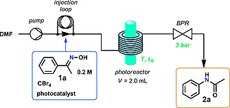
Schematic diagram of the continuous flow photoreactor system for the one‐pot photochemical Beckmann rearrangements.
Table 1.
|
| |||||||||
|---|---|---|---|---|---|---|---|---|---|
| Entry | Photocatalyst | CBr4 [mol‐%] | Time [min] | Light source [nm] | Molar fraction [%]b | ||||
| 1a | 2a | CBr4 c | |||||||
| 1 | Eosin Y | 200 | 10 | 515d | >99 | 0 | >99 | ||
| 2 | Rose Bengal | 200 | 10 | 515d | >99 | 0 | 94 | ||
| 3 | Ru(bpy)3Cl2 | 200 | 10 | 455 | 2 | 45 | 39 | ||
| 4 | Ru(bpy)3Cl2 | 100 | 10 | 455 | 4 | 53 | 21 | ||
| 5 | Ru(bpy)3Cl2 | 50 | 10 | 455 | 6 | 79 | 3 | ||
| 6 | Ru(bpy)3Cl2 | 25 | 10 | 455 | 88 | 8 | 0 | ||
| 7 | Ru(bpy)3Cl2 | 50 | 10 | 455d | 39 | 47 | 9 | ||
| 8 | Ru(bpy)3Cl2 | 50 | 20 | 455d | 8 | 68 | 0 | ||
The solution of reactants was degassed by Ar sparging for 15 min; 0.5 mL was injected for each run.
Determined by HPLC at 254 nm using p‐terphenyl as internal standard.
Unconverted CBr4 in the reaction mixture.
Reactions carried out in a glass chip reactor. A Vapourtec UV150 coil‐based system was used for entries 3–6.
When organic dyes (Eosin Y and rose Bengal) were employed as photocatalysts no conversion was observed (Table 1, entries 1 and 2). Notably, discoloration of the reaction mixture could be visually observed. The poor results could therefore be ascribed to bleaching of the organocatalysts under the reaction conditions used, due to the strong light irradiation and acidification of the reaction mixture (HBr formation). Acidic conditions may promote the formation of the lactone of Eosin Y, which does not absorb light efficiently. Indeed, in our hands, replication of the reaction conditions published in the literature17 for this transformation using Eosin Y in a batch reactor, resulted in insignificant amounts of the desired amide (< 2 %) (see Experimental Section for details). Using Ru(bpy)3Cl2 as photocatalyst and 2 equiv. of CBr4, formation of the desired acetanilide 2a was observed along with formamidine 6a and CO as side products (Table 1, entry 3). Formamidine 6a is most likely formed by the reaction of 2a with a second molecule of the V–H reagent,26 indicating an excess of the formation of the active species in the reaction mixture. In addition, the release of CO gas could be confirmed by attaching a CO detector to the reactor outlet. Thus, the amount of CBr4 loading was gradually reduced (Table 1, entries 4–6). The best yield for 2a was achieved when 50 mol‐% of CBr4 was used (Table 1, entry 5), in agreement with the theoretical stoichiometry required for the formation of 1 equiv. of V–H reagent (Scheme 4). Further reduction of the amount of CBr4 to 25 mol‐% resulted in reduced conversion (Table 1, entry 6), excluding a self‐propagative mechanism (Scheme 2a). The reaction using 50 mol‐% CBr4 could be reproduced in the glass chip reactor in which the experiments with 515 nm irradiation had been performed, although a longer residence time was required to achieve comparable conversion and yield (Table 1 entry 8). This initial set of experiments was performed at 40 °C, which corresponds to the temperature generated by the light source with air cooling.
Scheme 4.

Generation of the V–H reagent (5A) from CBr4 and DMF. 2 equiv. of the reactive species can be generated per mol of halide.
A series of control experiments was then performed using Ru(bpy)3Cl2 and 50 mol‐% of CBr4 (Table 1, entry 5). It could be demonstrated that the reaction is photocatalytic (Table 2), since no product (2a) was detected when the reaction was performed without photocatalyst (Table 2, entry 2), CBr4 (Table 2, entry 3) or light (Table 2, entry 4). Importantly, even in the absence of substrate (1a), 90 % of CBr4 was consumed by the oxidative quenching of the excited photocatalyst (Table 2, entry 5), demonstrating that V–H reagent formation and the subsequent Beckmann rearrangement are independent events. The reaction became slower at lower concentration (Table 2, entry 6). As HBr is formed during the reaction, the possibility that this protic acid acts as catalyst for the Beckmann rearrangement was explored. Thus, HBr instead of CBr4 was added to some of the reaction mixtures processed in the absence of light. No conversion was observed either at room temperature (Table 2, entry 7), or at elevated temperatures (Table 2, entries 8–10). Indeed, heating at 100 °C only resulted in partial hydrolysis of 1a (Table 2, entry 10). Additional experiments with varying reaction time and catalyst loading showed that it is possible to reduce the catalyst loading from 2 mol‐% to 1 mol‐% by increasing the residence time to 20 min (see Table S3 in the Supporting Information).
Table 2.
Control experiments for the one‐pot continuous photochemical Beckmann rearrangement of 1a (Figure 1)a
|
| |||||
|---|---|---|---|---|---|
| Entry | Variation from standard condition | Molar fraction [%]b | Remarks | ||
| 1a | 2a | CBr4 c | |||
| 1 | – | 6 | 79 | 3 | Standard |
| 2 | Without Ru(bpy)3Cl2 | > 99 | 0 | > 99 | |
| 3 | Without CBr4 | > 99 | 0 | – | |
| 4 | Without light | > 99 | 0 | > 99 | |
| 5 | Without substrate | – | – | 10 | |
| 6 | 0.1 M concentration | 14 | 67 | 1 | |
| 7 | 8 equiv. HBr | > 99 | 0 | – | No light |
| 8 | 8 equiv. HBr, 70 °C | 99 | 0 | – | No light |
| 9 | 4 equiv. HBr, 80 °C, 50 min | 98 | 0 | – | No light |
| 10 | 4 equiv. HBr, 100 °C, 50 min | 77 | 0 | – | No light, oxime hydrolysis |
The solution of reactants was degassed by Ar bubbling for 15 min; 0.5 mL was injected for each run.
Determined by HPLC at 254 nm using p‐terphenyl as internal standard.
Unconverted CBr4 in the reaction mixture.
Some of the experiments collected in Table 1 resulted in good conversions (>90 %) (entries 3–5) but yields for the desired product 2a were below 80 % in all cases (HPLC analysis with p‐terphenyl as internal standard). GC–MS analysis of a crude reaction mixture revealed the formation of several side‐products during the reaction (Scheme 5). A small amount of aniline (7a) (3 %), the hydrolysis product of formamidine 6a, could be detected by HPLC even when using 50 mol‐% of CBr4. Indeed, larger excess of CBr4 led to significant amounts of 7a (9 % when 100 mol‐% CBr4 was used) due to the excessive V–H reagent formation. A small amount of benzonitrile (9a) (1 %) was also generated via Beckmann fragmentation. This is a common side reaction in the Beckmann rearrangement. The major side product observed was isoxazolone 8a (16 %), which is most likely generated by oxidation of activated oxime 3a with a tribromomethyl radical following the mechanism shown in Scheme 6. The tribromomethyl radical (·CBr3) is generated from the oxidative quenching of the excited state of the photocatalyst (Ru(II)*) with CBr4. This radical then abstracts one electron from the N‐atom of activated oxime 3a, forming the radical cation 10a and a tribromomethyl carbanion. Deprotonation of the radical cation by the CBr3 anion generates bromoform (CHBr3) and radical 11a. Intermediate 11a undergoes 5‐exo‐trig cyclization, deprotonation, and single electron oxidation by Ru(III), recovering the catalyst and affording isoxazolone (8a). Notably, generation of CHBr3 could be confirmed by GC–MS analysis of the reaction mixture, supporting the radical mechanism depicted in Scheme 6.
Scheme 5.
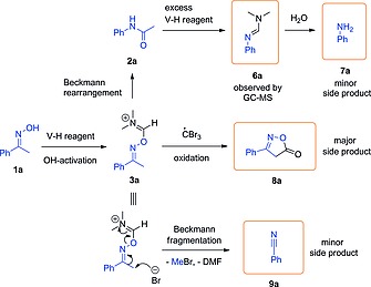
Detected side products (highlighted with frames) and their formation.
Scheme 6.
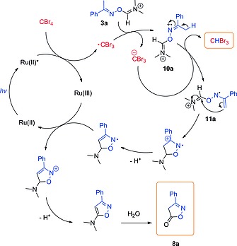
Postulated mechanism for the formation of isoxazolone 8a via photocatalyzed oxidation of 3a.
We next investigated the influence of temperature in the reaction using Ru(bpy)3Cl2 as photocatalyst and 50 mol‐% of CBr4 (Table 1, entry 5) (Figure 2). At temperatures above 40 °C the Beckmann rearrangement of 1a was fast enough to complete within 10 min. However, at lower temperatures lower conversion of 1a was observed, the reaction becoming completely inhibited at temperatures <10 °C. In contrast, the photochemical formation of the V–H reagent (which can be monitored by the consumption of CBr4) performed best at low temperatures, being quantitative at 0 °C. This effect can likely be attributed to the longer lifetime of the triplet state of Ru(bpy)3 2+ (Ru(II)*) at low temperatures27 This was further confirmed in a quenching experiment without substrate, in which CBr4 was consumed in a similar fashion and temperature dependence as observed in Figure 2 (See Table S2 in the Supporting Information). The variable temperature experiments indicate that the light‐induced Beckmann rearrangement using the one‐pot procedure is hampered by the fact that the photochemical and thermal steps of the reaction perform best in different temperature regimes. In addition, the one‐pot procedure combining light irradiation and exposure to 40 °C favors the formation of side‐product 8a.
Figure 2.
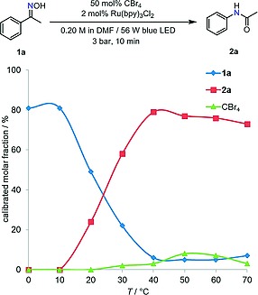
Effect of temperature on the one‐pot photochemical procedure (molar fractions were determined by HPLC at 254 nm using p‐terphenyl as internal standard).
Using continuous flow technology reactive intermediates can be generated on demand by combining several reactor units. This enabling technology has overcome the limitations of many processes in which intermediates or reagents, too hazardous to be generated or stored in large amounts, need to be generated and immediately consumed. Although V–H reagents are highly hygroscopic salts, they are relatively stable in solution if contact with moisture is avoided.28 In situ generation of a V–H reagent using conventional protocols (DMF + POCl3) for the formylation of pyrrole has also been reported in the literature.29 In the case of the photochemical rearrangement described herein, a two‐step flow arrangement permits to separate the photochemical and the thermal processes, avoiding undesired interactions of light or photochemically generated short lived intermediates with the substrate or the intermediates in the Beckmann rearrangement. We envisaged that this strategy would minimize the formation of side‐products and permit the independent operation of the two reaction steps (vide infra).
Sequential Two‐Step Flow Process
Based on the considerations above, a second continuous flow reactor system was constructed as shown in Figure 3. In this case, the output of the continuous photochemical reactor (Vapourtec UV150) was attached to a T‐mixer, in which a second reaction stream containing the oxime substrate 1a was introduced. The resulting mixture of substrate and V–H reagent then entered a second reactor unit (PFA tubing, 0.8 mm i.d., 10 mL) in which the rearrangement to 2a took place at elevated temperature.
Figure 3.
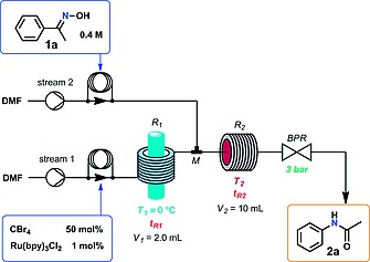
Schematic view of the continuous flow reactor utilized for the two‐step photochemical Beckmann rearrangement a Vapourtec E‐Series equipped with a UV150 photoreactor was utilized.
Using the two‐step system and setting the temperatures at 0 °C for the photochemical reactor and 40 °C for the Beckmann rearrangement reactor unit, excellent results were achieved (Table 3). Adjusting the residence times to 20 min and 50 min for the photochemical and thermal transformations, respectively, a 95 % HPLC assay yield of 2a was obtained (Table 3, entry 3). Notably, only insignificant amounts isoxazolone 8a could be detected in the crude reaction mixture, since the reaction mixture containing activated oxime 3a and Ru(bpy)3Cl2 was not exposed to blue light irradiation and most of the CBr4 was consumed during the V–H reagent formation before mixing with oxime 1a. Shorter reaction time led to incomplete conversion of both CBr4 and 1a (Table 3, entry 1); increasing the amount of CBr4 to 100 mol‐% did improve the conversion to some extent, but amide 2a was partially transformed into formamidine 6a under these conditions (Table 3, entry 2).
Table 3.
|
| ||||||
|---|---|---|---|---|---|---|
| Entry | tR 1 [min] | tR 2 [min] | CBr4 [mol‐%] | Molar fraction [%]b | ||
| 1a | 2a | CBr4 c | ||||
| 1 | 10 | 25 | 50 | 39 | 48 | 41 |
| 2 | 10 | 25 | 100 | 10 | 27 | 24 |
| 3 | 20 | 50 | 50 | 3 | 95 | 7 |
The solution for stream 1 was degassed by Ar sparging for 15 min; 0.8 mL for stream 1 and 0.5 mL solution for stream 2 were injected for each run; T 1 = 0 °C, T 2 = 40 °C.
Determined by HPLC at 254 nm using p‐terphenyl as internal standard.
Unconverted CBr4 in the reaction mixture.
With the optimal conditions in hand (Table 3 entry 3), a series of ketoximes was transformed to the corresponding amides using the two‐step continuous flow Beckmann rearrangement (Table 4).
Table 4.
Substrate scope for the continuous flow Beckmann rearrangement using a photochemically V–H reagent (Figure 3)a
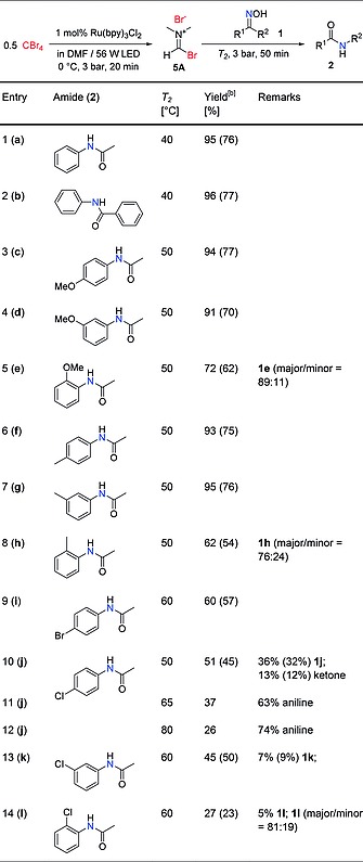
The solution for stream 1 was degassed by Ar sparging for 15 min; 4 mL solution for stream 1 and 3 mL (1.2 mmol) for stream 2 were injected for each run; T 1 = 0 °C.
Determined by HPLC peak area integration at 254 nm; the values in parenthesis are isolated yields.
The temperature for the second reactor unit (T2, Beckmann rearrangement) was adjusted in some cases to improve the yield of the target compound. All products were isolated by column chromatography after evaporating the crude reaction mixture collected from the reactor output under reduced pressure (see Experimental Section for details). Unsubstituted acetophenone oxime (1a) and benzophenone oxime (1b) were converted cleanly to amides (2a and 2b) at 40 °C (Table 4, entries 1–2). Substituted acetophenone oximes required 50 °C or higher temperatures, depending on the nature and position of the substituents. Thus, acetanilides decorated with electron donating groups in the aromatic ring (Table 4, entries 3–8) were obtained with good to excellent yields at 50 °C. Substrates bearing electron withdrawing groups generally required higher temperatures (60 °C) for the rearrangement, providing only low to moderate yields (Table 4, entries 9–14). In addition to a slower Beckmann rearrangement, the electron poor oximes as well as the resulting amides were more prone to hydrolysis, a side‐product observed for these reactions. The rearrangement of p‐chloroacetophenone oxime (1j) was especially slow, and a significant amount of the ketone resulting from hydrolysis of the oxime was obtained (Table 4, entry 10). Elevating the temperature resulted in higher conversion of the starting material, but also increased the degree of hydrolysis of the product (Table 4, entries 11 and 12). Ortho‐substituted acetophenone oximes (1e, 1h and 1l) provided lower yields compared to their meta and para isomers, since the formation of a highly solvated intermediate is disfavored by the steric hindrance. Although these oximes (1e, 1h and 1l) were isolated as mixture of E‐ and Z‐isomers14 (NMR spectra are collected in the Supporting Information), which in principle might lead to a mixture of the N‐methyl and N‐phenyl amide products, a single product (N‐phenyl) was obtained in all cases. This is most likely due to E/Z isomerization under the reaction condition30
Using the continuous flow setup and the optimal conditions, several aldoximes were also processed (Table 5). In this case, dehydration of the substrate takes place, resulting in the corresponding nitrile. These reactions required higher temperatures for the second reactor unit (80 °C), and only performed well when electron‐rich aldoximes were utilized as substrates (Table 5, entry 1). The oximes of benzaldehyde (Table 5, entry 2) and 4‐chlorobenzaldehyde (Table 5, entry 3) exhibited low reactivity.
Table 5.
Substrate scope for the continuous flow aldoxime dehydration using a photochemically generated V–H reagent (Figure 3)a
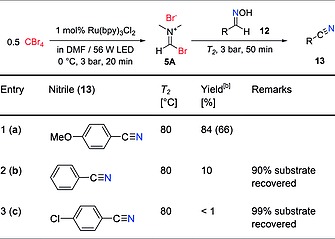
The solution for stream 1 was degassed by Ar sparging for 15 min; 4 mL solution for stream 1 and 3 mL (1.2 mmol) for stream 2 were injected for each run; T 1 = 0 °C.
Determined by HPLC peak area integration at 254 nm; the values in parenthesis are isolated yields.
Proposed Reaction Mechanism
Based on previously suggested reaction mechanisms17, 18 and evidence obtained during the reaction optimization in this work, including the detection of several important by‐products, a plausible pathway for the visible light‐promoted Beckmann rearrangement was postulated (Scheme 7a). The catalyst Ru(bpy)3 2+ (Ru(II)) is excited to a reductive triplet state Ru(bpy)3 2+* (Ru(II)*) upon blue light irradiation, and thereafter quenched by CBr4, releasing Br– and a ·CBr3 radical. The electrophilic ·CBr3 radical then adds to a DMF molecule, and the resulting complex is oxidized to the iminium cation 14 by Ru(III), regenerating the catalyst. Intermediate 14 decomposes to the V–H reagent 5A and bromophosgene (15). As its chlorinated counterpart phosgene,[11c] 15 is able to react with a second DMF molecule, generating an additional equivalent of V–H reagent, accounting for the reaction stoichiometry confirmed experimentally (cf. Scheme 4). The hydroxy group in oxime 1 is activated by 5A, undergoing substituent migration and hydrolysis to afford the amide product 2 (non‐self‐propagative Beckmann rearrangement). In the case of aldoximes 12, nitriles 13 are formed after elimination of DMF and a proton (Scheme 7b).
Scheme 7.
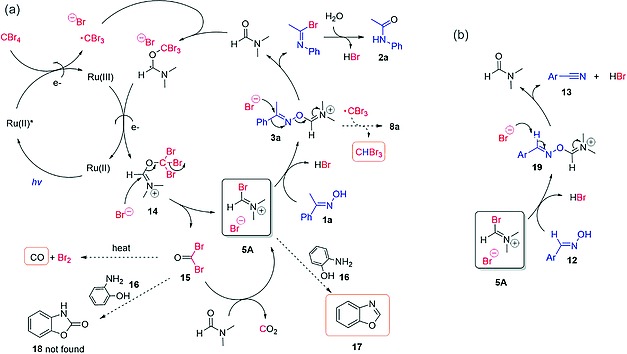
Postulated mechanism for the (a) Beckmann rearrangement and (b) aldoxime dehydration promoted by the photochemically generated V–H reagent.
Bromophosgene 15 is an electrophile, and therefore can directly activate the oxime OH group without forming intermediate 5A. An attempt to trap 15 was made by adding 2‐aminophenol (16) as scavenger to the reaction mixture (See Supporting Information for details). However, only benzoxazole (17) was detected in the reaction mixture instead of benzoxazolone (18), indicating the presence of a formylating agent, namely 5A, and not the carbonylating agent 15. Due to the instability and the reactivity of 15, it is likely to be formed and consumed very rapidly; but the formation of CO (detected by CO sensor at the outlet) (Table 1, entry 3–4) can be explained by the transient presence of 15, since it is the only species that decomposes to CO under the reaction condition.31 Isoxazolone (8a) could be formed by oxidation of 3a with the ·CBr3 radical, as shown in detail in Scheme 6.
Conclusions
In summary, we have developed a continuous flow procedure for the light‐induced Beckmann rearrangement. A Vilsmeier–Haack reagent, generated by means of photoredox catalysis, acts as electrophile to promote the rearrangement. Execution of the two‐step reaction in one pot proved troublesome due to the different reaction conditions, in particular temperature, optimal for the light‐induced and thermal processes. These limitations have been overcome by disentangling the photochemical and thermal phenomena in an integrated, two‐step sequential continuous flow process. Thus, the electrophilic species is initially generated in a flow photoreactor at low temperature, and then mixed with the substrate and reacted in a second flow reactor at elevated temperature. Using this approach a diverse set of oximes have been transformed into the corresponding amides under mild conditions without the need of hazardous reagents typically required for this transformation. Moderate to excellent product yields have been obtained after purification by column chromatography. The procedure has also been applied to aldoximes, providing the corresponding nitriles, although only electron‐rich substrates performed well. In addition, several reaction intermediates and side‐products of the reaction have been detected, shedding light to the reaction mechanism.
Experimental Section
Eosin Y–Catalyzed Beckmann Rearrangement of Acetophenone Oxime (1a) in Batch (Ref. 17). In an attempt to reproduce the results published by Yadav and co‐workers,17 acetophenone oxime 1a (54 mg, 0.4 mmol), CBr4 265.3 mg (0.8 mmol, 200 mol‐%), Eosin Y disodium salt 5.5 mg (0.008 mmol, 2 mol‐%), DMF 8 µL (25 mol‐%) and acetonitrile 2 mL were placed in a 2 mL Pyrex microwave vial. The vial was capped with a septum and degassed by argon sparging for 15 min. The vial was then irradiated with a green LED (515 nm, 50 W) placed 20 cm away from the test tube whilst stirring for 20 h. An aliquot (150 µL) of the crude reaction mixture was diluted with MeCN (1.5 mL) and analysed by HPLC (254 nm). Peak area integration of the HPLC chromatogram revealed < 2 % yield to the desired product 2a.
Visible Light‐Promoted Beckmann Rearrangement of Acetophenone Oxime (1a) (Optimization Experiments). Using the setup shown in Figure 1, after warming‐up of the light source and stabilization of the temperature and pressure, 0.5 mL reactant solution (degassed by 15 min argon sparging) was pumped into the reactor through an injection loop and collected at the outlet with a 5 mL volumetric flask containing 500 µL 0.02 M dichloromethane solution of p‐terphenyl (internal standard); the resulting mixture was diluted to 5.000 mL with acetonitrile for HPLC analysis.
Two‐Step Visible Light‐Promoted Beckmann Rearrangement of Ketoximes (1). Using the setup shown in Figure 3 (Flow rates: F 1 = F 2 = 100 µL/min), after warming of the light source and stabilization of the temperatures and pressure, a 4 mL solution of CBr4 (0.2 M) and Ru(bpy)3Cl2 (0.004 M) (degassed by 15 min Ar sparging) was pumped into the reactor (R1) through an injection loop; after 23 min, a 3 mL solution of 1 (0.4 M) was pumped into the T‐mixer (M) through a second injection loop. The reaction mixture was collected at the outlet with a glass vessel. During the collection, a drop of reaction mixture was sampled and diluted with acetonitrile in a standard 2 mL HPLC vial for HPLC analysis. After the collection, the reaction mixture was concentrated to ca. 3 mL in vacuo, dissolved in 25 mL pf CHCl3, washed with 3 × 25 mL distilled water, dried with anhydrous Na2SO4 and concentrated in vacuo. The residue was purified by flash chromatography on silica gel (40–63 µm) using petroleum ether (PE, 40–60 °C) and a 1:1 mixture of dichloromethane and ethyl acetate (DCM/EA) as eluent (Gradient: 0–15 % DCM/EA over 10 CV, maintained at 15 % DCM/EA over 15 CV, 15–80 % DCM/EA over 20 CV) to afford products 2.
Supporting information
Supporting Information
Acknowledgements
The CC FLOW Project (Austrian Research Promotion Agency FFG No. 862766) is funded through the Austrian COMET Program by the Austrian Federal Ministry of Transport, Innovation and Technology (BMVIT), the Austrian Federal Ministry of Science, Research and Economy (BMWFW), and by the State of Styria (Styrian Funding Agency SFG).
References
- 1. Beckmann B., Ber. Dtsch. Chem. Ges., 1886, 19, 988–993. [Google Scholar]
- 2.a) White J. D., Hrnciar P. and Stappenbeck F., J. Org. Chem., 1999, 64, 7871–7884; [Google Scholar]; b) White J. D. and Choi Y., Org. Lett., 2000, 2, 2373–2376. [DOI] [PubMed] [Google Scholar]
- 3.a) Ghiaci M., Aghaei H., Oroojeni M., Aghabarari B., Rives V., Vicente M. A., Sobrados I. and Sanz J., Catal. Commun., 2009, 10, 1486–1492; [Google Scholar]; b) Tabata H., Wada N., Takada Y., Oshitari T., Takahashi H. and Natsugari H., J. Org. Chem., 2011, 76, 5123–5131. [DOI] [PubMed] [Google Scholar]
- 4.a) Blatt A. H., Chem. Rev., 1933, 12, 215–260; [Google Scholar]; b) Donaruma L. G. and Heldt W. Z., Org. React., 1960, 11, 1–156. [Google Scholar]
- 5.a) Marvel C. S. and Eck J. C., Org. Synth., 1937, 17, 60; [Google Scholar]; b) Taber D. F. and Straney P. J., J. Chem. Educ., 2010, 87, 1392–1392; [Google Scholar]; c) Hashimoto M., Obora Y. and Ishii Y., Org. Process Res. Dev., 2009, 13, 411–414. [Google Scholar]
- 6.a) Wang B., Gu Y., Luo C., Yang T., Yang L. and Suo J., Tetrahedron Lett., 2004, 45, 3369–3372; [Google Scholar]; b) Lin S.‐Y., Yeh T.‐K., Kuo C.‐C., Song J.‐S., Cheng M.‐F., Liao F.‐Y., Chao M.‐W., Huang H.‐L., Chen Y.‐L., Yang Ch.‐Y., Wu M.‐H., Hsieh C.‐L., Hsiao W., Peng Y.‐H., Wu J.‐S., Lin L.‐M., Sun M., Chao Y.‐S., Shih C., Wu S.‐Y., Pan S.‐L., Hung M.‐S. and Ueng S.‐H., J. Med. Chem., 2016, 59, 419–430; [DOI] [PubMed] [Google Scholar]; c) Zhang J., Dong C., Du C. and Luo G., Org. Process Res. Dev., 2015, 19, 352–356. [Google Scholar]
- 7.a) Zicmanis A., Katkevica S. and Mekss P., Catal. Commun., 2009, 10, 614–619; [Google Scholar]; b) Boruah M. and Konwar D., J. Org. Chem., 2002, 67, 7138–7139; [DOI] [PubMed] [Google Scholar]; c) Ramalingan C. and Park Y.‐T., J. Org. Chem., 2007, 72, 4536–4538; [DOI] [PubMed] [Google Scholar]; d) Mahajan S., Sharma B. and Kapoor K. K., Tetrahedron Lett., 2015, 56, 1915–1918; [Google Scholar]; e) Hashimoto M., Obora Y., Sakaguchi S. and Ishii Y., J. Org. Chem., 2008, 73, 2894–2897; [DOI] [PubMed] [Google Scholar]; f) Kiely‐Collins H. J., Sechi I., Brennan P. E. and McLaughlin M. G., Chem. Commun., 2018, 54, 654–657. [DOI] [PubMed] [Google Scholar]
- 8.a) Furuya Y., Ishihara K. and Yamamoto H., J. Am. Chem. Soc., 2005, 127, 11240–11241; [DOI] [PubMed] [Google Scholar]; b) Gao Y., Liu J., Li Z., Guo T., Xu S., Zhu H., Wei F., Chen S., Gebru H. and Guo K., J. Org. Chem., 2018, 83, 2040–2049. [DOI] [PubMed] [Google Scholar]
- 9.a) Vanos C. M. and Lambert T. H., Chem. Sci., 2010, 1, 705–708; [Google Scholar]; b) Gao P. and Bai Z., Chin. J. Chem., 2017, 35, 1673–1677; [Google Scholar]; c) Fernandez‐Stefanuto V., Verdia P. and Tojo E., New J. Chem., 2017, 41, 12830. [Google Scholar]
- 10.a) An N., Tian B.‐X., Pi H.‐J., Eriksson L. A. and Deng W.‐P., J. Org. Chem., 2013, 78, 4297–4302; [DOI] [PubMed] [Google Scholar]; b) Tian B.‐X., An N., Deng W.‐P. and Eriksson L. A., J. Org. Chem., 2013, 78, 6782–6785. [DOI] [PubMed] [Google Scholar]
- 11.a) de Luca L., Giacomelli G. and Porcheddu A., J. Org. Chem., 2002, 67, 6272–6274; [DOI] [PubMed] [Google Scholar]; b) Narahari S. R., Reguri B. R. and Mukkanti K., Tetrahedron Lett., 2011, 52, 4888–4891; [Google Scholar]; c) Su W. K., Zhang Y., Li J. J. and Li P., Org. Prep. Proced. Int., 2008, 40, 543–550. [Google Scholar]
- 12. Fujita S., Koyama K. and Inagaki Y., Synthesis, 1982, 1982, 68–69. [Google Scholar]
- 13. Zhou A., Zheng D., Zhu X. and Wang M., Chin. J. Org. Chem., 2018, 38, 2905–2910. [Google Scholar]
- 14. Mo X., Morgan T. D. R., Ang H. T. and Hall D. G., J. Am. Chem. Soc., 2018, 140, 5264–5271. [DOI] [PubMed] [Google Scholar]
- 15. Mahajan P. S., Humne V. T., Tanpure S. D. and Mhaske S. B., Org. Lett., 2016, 18, 3450–3453. [DOI] [PubMed] [Google Scholar]
- 16.a) Taylor R. T., Douek M. and Just G., Tetrahedron Lett., 1966, 7, 4143–4148; [Google Scholar]; b) Izawa H., De Mayo P. and Tabata T., Can. J. Chem., 1969, 1, 51–62; [Google Scholar]; c) Suginome H. and Uchida T., Tetrahedron Lett., 1973, 25, 2293–2296. [Google Scholar]
- 17. Srivastava V. P., Yadav A. K. and Yadav L. D. S., Synlett, 2014, 25, 665–670. [Google Scholar]
- 18.a) Dai C., Narayanam J. M. R. and Stephenson C. R. J., Nat. Chem., 2011, 3, 140–145; [DOI] [PubMed] [Google Scholar]; b) Minozzi C., Grenier‐Petel J.‐C., Parisien‐Collette S. and Collins S. K., Beilstein J. Org. Chem., 2018, 14, 2730–2736. [DOI] [PMC free article] [PubMed] [Google Scholar]
- 19. Yadav A. K., Srivastava V. P. and Yadav L. D. S., RSC Adv., 2014, 4, 4181–4186. [Google Scholar]
- 20. Konieczynska M. D., Dai C. and Stephenson C. R. J., Org. Biomol. Chem., 2012, 10, 4509–4511. [DOI] [PubMed] [Google Scholar]
- 21. Yadav A. K., Srivastava V. P. and Yadav L. D. S., RSC Adv., 2014, 4, 24498–24503. [Google Scholar]
- 22. Zhao Y., Huang B., Yang C., Chen Q. and Xia W., Org. Lett., 2016, 18, 5572–5575. [DOI] [PubMed] [Google Scholar]
- 23.a) Gilmore K. and Seeberger P. H., Chem. Rec., 2014, 14, 410–418; [DOI] [PubMed] [Google Scholar]; b) Elliott L. D., Knowles J. P., Koovits P. J., Maskill K. G., Ralph M. J., Lejeune G., Edwards L. J., Robinson R. I., Clemens I. R., Cox B., Pascoe D. D., Koch G., Eberle M., Berry M. B. and Booker‐Milburn K. I., Chem. Eur. J., 2014, 20, 15226–15232. [DOI] [PubMed] [Google Scholar]
- 24.a) Cambié D., Bottecchia C., Straathof N. J. W., Hessel V. and Noël T., Chem. Rev., 2016, 116, 10276–10341; [DOI] [PubMed] [Google Scholar]; b) Su Y., Straathof N. J. W., Hessel V. and Noël T., Chem. Eur. J., 2014, 20, 10562–10589; [DOI] [PubMed] [Google Scholar]; c) Schuster E. M. and Wipf P., Isr. J. Chem., 2014, 54, 361–370. [Google Scholar]
- 25. Jödecke M., Pérez‐Salado Kamps A. and Maurer G., J. Chem. Eng. Data, 2012, 57, 1249–1266. [Google Scholar]
- 26. Bésán J., Kulcsár L. and Kovács M., Synthesis, 1980, 1980, 883. [Google Scholar]
- 27. Brennaman M. K., Meyer T. J. and Papanikolas J. M., J. Phys. Chem. A, 2004, 108, 9938–9944. [Google Scholar]
- 28.a) Kikugawa K. and Kawashima T., Chem. Pharm. Bull., 1971, 19, 2629–2630; [Google Scholar]; b) Arnold Z. and Holy A., Collect. Czech. Chem. Commun., 1961, 26, 3059; [Google Scholar]; c) Marson C. M., Tetrahedron, 1992, 48, 3659–3726. [Google Scholar]
- 29. van den Broek S. A. M. W., Leliveld J. R., Becker R., Delville M. M. E., Nieuwland P. J., Koch K. and Rutjes F. P. J. T., Org. Process Res. Dev., 2012, 16, 934–938. [Google Scholar]
- 30. Pereira M. M. A., Santos P. P., in: The Chemistry of Hydroxylamines, Oximes and Hydroxamic Acids (Eds.: Rappoport Z. and Liebman J. F.), John Wiley & Sons, Ltd. 2009, pp. 343–498. [Google Scholar]
- 31. Ryan T. A., Ryan C., Seddon E. A. and Seddon K., in Phosgene: And Related Carbonyl Halides; Elsvier Science B. V. 2009, pp. 665–678. [Google Scholar]
Associated Data
This section collects any data citations, data availability statements, or supplementary materials included in this article.
Supplementary Materials
Supporting Information


