Significance
Use of a flexible solid polymer electrolyte is a common strategy to obtain an all-solid-state lithium battery of high stored electric power at acceptable charge–discharge cycling rates. Commercial realization of this strategy with poly(ethylene oxide) containing a garnet ceramic has been unsuccessful and dendrites form and grow across garnet electrolytes without proper treatment of the garnet surface. We report that use of a perovskite Li+ electrolyte in place of the garnet ceramic provides an adequate Li+ conductivity at 25 °C without dendrite formation. We also demonstrate a binding of the TFSI− anion of a LiTFSI [lithium bis(trifluoromethanesulfonyl)imide] salt to the polymer, which increases both the Li+ conductivity and the Li+ transport number.
Keywords: polymer electrolyte, high conductivity, solid-state batteries, high-voltage cathode
Abstract
Flexible and low-cost poly(ethylene oxide) (PEO)-based electrolytes are promising for all-solid-state Li-metal batteries because of their compatibility with a metallic lithium anode. However, the low room-temperature Li-ion conductivity of PEO solid electrolytes and severe lithium-dendrite growth limit their application in high-energy Li-metal batteries. Here we prepared a PEO/perovskite Li3/8Sr7/16Ta3/4Zr1/4O3 composite electrolyte with a Li-ion conductivity of 5.4 × 10⁻⁵ and 3.5 × 10⁻⁴ S cm−1 at 25 and 45 °C, respectively; the strong interaction between the F− of TFSI− (bis-trifluoromethanesulfonimide) and the surface Ta5+ of the perovskite improves the Li-ion transport at the PEO/perovskite interface. A symmetric Li/composite electrolyte/Li cell shows an excellent cyclability at a high current density up to 0.6 mA cm−2. A solid electrolyte interphase layer formed in situ between the metallic lithium anode and the composite electrolyte suppresses lithium-dendrite formation and growth. All-solid-state Li|LiFePO4 and high-voltage Li|LiNi0.8Mn0.1Co0.1O2 batteries with the composite electrolyte have an impressive performance with high Coulombic efficiencies, small overpotentials, and good cycling stability.
The growing demand for portable electronic equipment powered by a rechargeable battery and for electric-powered road vehicles calls for the development of safe, low-cost rechargeable lithium or sodium batteries to replace the existing Li-ion battery. This development can be done by a replacement of the liquid electrolyte by a plastic solid electrolyte with a large enough energy gap to contain the electrochemical potentials of a Li-metal anode and a high-voltage cathode provided the electrolyte has a Li+ conductivity σLi > 10−3⋅S cm−1 at room temperature (1–3). Poly(ethylene oxide) (PEO)-based polymer electrolytes are one of the most promising solid electrolytes because of their low lattice energy, high flexibility, simple preparation, and capability of solvating lithium salts (4, 5). However, the low ionic conductivity (∼10−6 to 10−7 S cm−1) and poor mechanical properties restrict their practical application (6, 7). Crystalline ceramic electrolytes have a higher Li-ion conductivity of 10−5 to 10−3 S cm−1 at 25 °C, but they exhibit a large interfacial resistance due to a poor contact with solid electrodes (8–10). Incorporating Li-ion conducting solid ceramic oxides into a flexible PEO polymer electrolyte matrix can increase the Li-ion conductivity of PEO 1) by reducing the PEO crystallization that hinders Li-ion transport in PEO, 2) by creating fast Li-ion transport channels on the PEO/ceramic interface, and 3) by allowing fast Li+ transport in the ceramic itself (11). Moreover, introduction of a ceramic Li-ion conductor into PEO increases the mechanical strength of the membrane and can suppress the penetration of lithium dendrites (12–17). Garnet (e.g., Li7La3Zr2O12) and perovskite Li0.33La0.56TiO3 with various morphologies have been reported to increase the performance of PEO as a Li-ion conductor (18–22). However, the garnet electrolyte is unstable in air, causing the development of a layer with low ionic conductivity on its surface. Perovskite Li0.33La0.56TiO3 (LLTO) with a high bulk Li-ion conductivity of 10−3 S cm−1 at 25 °C is reduced by a metallic lithium anode. Also, the LLTO surface is lithium-deficient, which blocks the Li ions from transferring between LLTO and PEO. To date, the ionic conductivity of the composite polymer electrolytes is still not high enough to meet practical requirements for all-solid-state batteries.
The perovskite Li3/8Sr7/16Ta3/4Zr1/4O3 (LSTZ) electrolyte has recently been reported to be stable in moist air (23). The good stability enables a small interfacial resistance between PEO and an LSTZ particle since no Li+ insulating phase forms on the surface of LSTZ. In addition, LSTZ has a high bulk Li-ion conductivity of ∼10−3 S cm−1 at 25 °C. Herein we report a solid composite electrolyte of PEO/LiTFSI/LSTZ (denoted as PEO/LSTZ) with perovskite LSTZ as a filler. Although several others have investigated the use in an all-solid-state rechargeable battery of a flexible composite Li+-electrolyte membrane consisting of a PEO polymer containing ceramic particles as fillers, our strategy is the choice of the LSTZ ceramic for this application. Benefiting from the LSTZ filler, the composite electrolyte has a Li+-ion conductivity of 5.4 × 10⁻⁵ S cm−1 at 25 °C and 3.5 × 10⁻⁴ S cm−1 at 45 °C, respectively.
The increased Li+ transport number in PEO/LSTZ originates from a strong chemical Ta–F bond that immobilizes the anions based on the results of X-ray photoelectron spectroscopy (XPS), NMR spectroscopy, and density-functional theory (DFT) calculations. Moreover, the Li/composite–electrolyte interface is stabilized by an in situ formation of a solid electrolyte interphase layer that effectively suppresses Li-dendrite growth. We show that a symmetric Li|Li cell, an all-solid-state Li|LiFePO4 (LFP) cell, and a Li|LiNi0.8Mn0.1Co0.1O2 (NMC) cell with this polymer electrolyte all deliver an excellent cycling stability and rate capability at 45 °C. The cells reported previously with these PEO-based composite electrolytes were mostly tested at a temperature above 55 °C due to the low ionic conductivity of the composite electrolytes. However, the PEO-based electrolytes would melt to become gel electrolytes at such high temperatures, which make them unable to suppress lithium dendrite formation. Our LFP|PEO/LSTZ|Li cell can run over 350 cycles with a negligible capacity fade at 45 °C due to the stable all-solid-state components. We further took a protection stratagem to test the polymer electrolyte with a high-voltage Ni-rich cathode; the cell exhibits an impressive performance.
Results and Discussion
Li-Ion Transport of the Composite PEO/LSTZ Electrolyte.
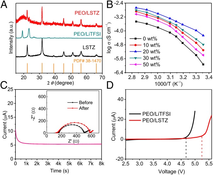
The perovskite LSTZ employed in this work has a high bulk Li-ion conductivity of 1 × 10⁻³ S cm−1 at room temperature and does not have a Li-ion insulating Li2CO3 phase on the particle surface (SI Appendix, Fig. S1). The PEO/LSTZ membrane with LiTFSI salt was prepared by a facile solution-cast method.(18) The obtained composite membrane is smooth, freestanding, and mechanically flexible (SI Appendix, Fig. S2 A and B). LSTZ particles with an average size of 1 μm (SI Appendix, Fig. S2 C and D) are uniformly dispersed in the PEO/LiTFSI matrix (SI Appendix, Fig. S2E). The distribution of Ta from LSTZ matches well with the F and C from the PEO/LiTFSI matrix (SI Appendix, Fig. S2F), which indicates that PEO chains, Li+, and TFSI− are fully entangled with LSTZ particles. LSTZ is stable in PEO and reduces the degree of crystallinity in the PEO (Fig. 1A), which releases more PEO chains to promote Li+ transport along/between PEO chains (24, 25). The Arrhenius plots of the PEO/LSTZ membranes with varying wt % of LSTZ are shown in Fig. 1B. The perovskite LSTZ significantly increases the Li-ion conductivity of the PEO/LiTFSI, and the composite with 20 wt % LSTZ exhibits the highest conductivity of 5.4 × 10⁻⁵ and 3.5 × 10⁻⁴ S cm−1 at 25 and 45 °C, respectively (SI Appendix, Fig. S3A); it also has a higher Li-ion transference number (tLi+) of 0.43 (Fig. 1C) than those of PEO composites with other Li-ion insulating or conducting fillers such as Al2O3 and garnet Li7La3Zr2O12 (26, 27). This result indicates that the LSTZ surface interacts with the TFSI− to limit its mobility, freeing Li+ ions for transport. The introduction of LSTZ to PEO/LiTFISI also increases the stability of the membrane to a higher voltage (Fig. 1D).
Fig. 1.
Characterization of the PEO/LSTZ membrane. (A) XRD patterns of LSTZ powder, PEO/LiTFSI, and PEO/LSTZ membrane with 20 wt % LSTZ. (B) Arrhenius plots of the PEO/LSTZ membranes with varying wt % of LSTZ. (C) Current–time profile of the Li symmetrical cell with PEO/LSTZ composite electrolyte at an applied voltage of 10 mV. (Inset) Impedance spectra before and after polarization. (D) Linear sweep voltammetry curves of the PEO/LiTFSI and PEO/LSTZ electrolytes.
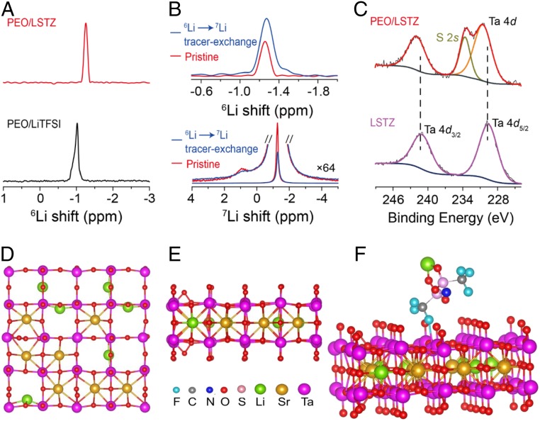
The Li+ ions of the PEO/LSTZ composite can transport 1) through the PEO, 2) at the PEO/LSTZ interface, and 3) through the LSTZ grains. The amorphous PEO with flexible chain segments in the PEO/LSTZ composite increases the Li-ion conductivity. The higher Li-ion conductivity of PEO/LSTZ than that of PEO at temperatures above 60 °C, where PEO is amorphous, indicates a contribution of Li-ion transport through LSTZ grains and grain surfaces. NMR was employed to study the Li+ environment and Li-ion transport pathways in the composite electrolyte. The 6Li LiTFSI signal in PEO/LSTZ shifts to a higher frequency (smaller ppm) compared to PEO/LiTFSI (Fig. 2A); up-field shifting of 6Li LiTFSI resonance in the PEO/LSTZ complex indicates that PEO/LiTFSI interactions are weakened by the addition of LSTZ (28, 29). No 6Li perovskite signal is observed due to the dilute Li content from perovskite in the composite. A decreased FWHM of the 6Li resonance from the LiTFSI peak also implies faster Li-ion motion in PEO/LSTZ, which averages out the inhomogeneous broadening associated with an anisotropic distribution of Li local environments; therefore, the Li ions from LiTFSI tend to move more freely, which agrees well with the increased Li+ conductivity.
Fig. 2.
(A) High-resolution 6Li MAS NMR spectra of PEO/LiTFSI and PEO/LSTZ samples. (B) 6Li →7Li tracer-exchange NMR of PEO/LSTZ before (red) and after (blue) cycling against 6Li metal: 6Li NMR spectra is above the 7Li. (C) High-resolution Ta 4d XPS spectra of LSTZ and PEO/LSTZ composite; the peak at 233.6 eV is assigned to S 2s from the LiTFSI in PEO/LSTZ. The top (D) and side views (E) of the perovskite (001) atomic structure. (F) The crystallographic structure of LiTFSI adsorbed on the O-terminated (001) surface of the perovskite with 1 O vacancy.
To probe the Li-ion transport pathway in PEO/LSTZ, 6Li →7Li tracer-exchange NMR (30) was employed (Fig. 2B). A significant increase in intensity of the 6Li LiTFSI peak is observed after cycling with 6Li electrodes at 10 μAcm−2 for 100 cycles. In contrast, 7Li spectra reveal a signal loss in the 7Li resonance of LiTFSI; the loss from the LiTFSI is more notable than from the perovskite. As a result, the enhanced 6Li signal from LiTFSI indicates that the Li+ ions preferentially transport through the PEO/LiTFSI matrix near the perovskite particles. The contribution of Li+ ions of LSTZ grains to the total Li-ion conductivity in the composite cannot be determined owing to the small population of Li+ ions in LSTZ; however, a previous report on PEO/garnet confirmed that the Li ions from the fast Li-ion conductors participate in the Li-ion transport in the composite (30). Compared to the garnet, the LSTZ has a similar bulk Li-ion conductivity of 10−3 S cm−1 at 25 °C, but a much smaller interfacial resistance with PEO (SI Appendix, Fig. S3B). The smaller interfacial resistance of the PEO|LSTZ than that of PEO|LLZT proves that LSTZ is much more effective in promoting the Li+ transport in the PEO/LiTFSI matrix (31). Garnet LLZT reacts with moist air to form a layer of Li+-insulating Li2CO3 on its surface (SI Appendix, Fig. S4 A and B), which blocks the Li-ion transfer across the garnet/PEO interface. The improved transference number (tLi+) and Li-ion conductivity of the PEO/LSTZ composite than those of PEO indicate a strong interaction of the TFSI− anion and LSTZ grain surface. The two Ta 4d peaks in the LSTZ XPS spectrum shift to a higher binding energy in the PEO/LSTZ composite (Fig. 2C) while there are no obvious shifts for either Sr 3d or Zr 3d peaks (SI Appendix, Fig. S4 C and D), indicating only the Ta5+ of perovskite LSTZ interacts with the PEO/LiTFSI matrix. In comparison, the Ta 4d peaks in LLZT did not show any obvious shift when compositing with PEO (SI Appendix, Fig. S4E), which indicates that the Ta in LLZT does not interact with PEO/LiTFSI. DFT calculations for LiTFSI adsorption on the perovskite (001) surface (Fig. 2 D and E) were conducted to study this interaction. O-terminated rather than Ta-terminated (001) surface of perovskite was selected as the stable adsorption substrate (SI Appendix, Fig. S5A). The differential charge density result further verifies the strong interaction between TFSI anion and LSTZ substrate (SI Appendix, Fig. S5B). As shown in Fig. 2F, the Ta5+–F− binding energy is increased to 0.34 eV, which reduces the binding energy of Li+ to TFSI− by 0.26 eV. These calculations indicate Li+ ions are released into the composite because of a much easier dissociation of LiTFSI salts in the composite than in normal PEO owing to the addition of LSTZ. In summary, as well as stabilizing the amorphousness of PEO, the addition of highly conductive LSTZ filler plays a key role in enhancing the Li+ ionic conductivity of the composite via strong chemical coupling between the perovskite LSTZ and TFSI− anions through Ta5+–F− bonding at the PEO/LSTZ interface.
The Symmetric Li/Li Cell and the Li/Composite Electrolyte Interface.
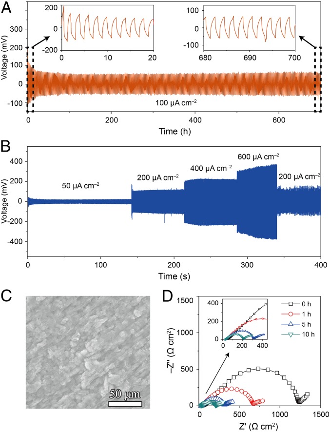
A symmetric Li|PEO/LSTZ|Li cell was assembled and cycled to evaluate the long-term electrochemical stability of PEO/LSTZ against Li metal. Fig. 3A presents the voltage profiles of the cell at 100 μA cm−2 and 45 °C; the cell exhibits a stable plating/stripping process over 700 h with a small overpotential of 57 mV. In comparison, the symmetric cell with a PEO/LiTFSI only cycled less than 200 h before short-circuiting (SI Appendix, Fig. S6A), indicating an efficient suppression of lithium-dendrite growth by the LSTZ filler. The Li|PEO/LSTZ|Li cell tested at 25 °C exhibits a large overpotential of 260 mV at 100 μA cm−2 (SI Appendix, Fig. S6B). The symmetric cell was also cycled at different current densities to evaluate the ability of the composite electrolyte to prevent lithium-dendrite growth. The symmetric cell with PEO/LSTZ cycled stably and exhibited low overpotentials of 22, 110, 205, and 310 mV at 50, 200, 400, and 600 μA cm−2, respectively (Fig. 3B). However, the cell became short-circuited when cycled at 800 μA cm−2 for 12 h (SI Appendix, Fig. S6C). The cycled Li metal surface with PEO/LSTZ electrolyte (Fig. 3C) does not show any apparent lithium-dendrite growth compared to the original lithium metal (SI Appendix, Fig. S6D) except for some deposited granules. However, the cell with PEO/LiTFSI electrolyte shows much larger particles on the cycled lithium surface than those with PEO/LSTZ electrolyte (SI Appendix, Fig. S6E). The LSTZ in the composite not only increases the Li+ conductivity, but also enhances the mechanical strength and suppresses the growth of lithium dendrites to ensure a long-cycle life. Perovskite LSTZ is reported to be unstable below 1.4 V and becomes black when contacting lithium metal (SI Appendix, Fig. S7A). This pristine and black LSTZ keeps the same perovskite structure (SI Appendix, Fig. S7B). The reduction of LSTZ may arise from impurities in the grain boundaries of LSTZ rather than from the LSTZ itself. When compositing with PEO, the LSTZ particles become shielded from being reduced by Li metal. The cycled PEO/LSTZ membrane shown in SI Appendix, Fig. S7C remains white after cycling, which confirms its good electrochemical stability against Li metal.
Fig. 3.
(A) Long-term plating/stripping test in Li|PEO/LSTZ|Li symmetric cell at 100 μA cm−2, and (B) at current densities from 50 to 600 μA cm−2 at 45 °C. (C) The surface of Li metal after cycling the symmetric cell with PEO/LSTZ electrolytes for 700 h at 100 μA cm−2 and 45 °C. (D) Impedance spectra of the symmetric cell measured after different cycling times at 45 °C.
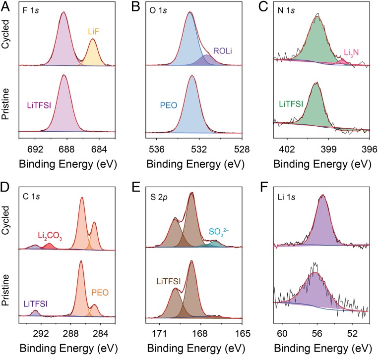
Impedance spectra of a symmetric cell collected after different cycling times (0–10 h) are shown in Fig. 3D. The Li/composite interfacial resistance decreased from 595 to 90 Ω cm2 after 10 h, indicating the formation of a stable solid electrolyte interphase between the metallic Li anode and the composite electrolyte (32–34). A similar phenomenon of a decreased Li/composite interfacial resistance was also observed for the symmetric cell without the lithium plating–stripping process (SI Appendix, Fig. S8), which excludes the possibility of the formation of high-surface-area lithium in the interface of Li|PEO/LiTFSI. Pristine and cycled PEO/LSTZ was measured with XPS to investigate the evolution of the Li/composite interface before and after cycling. As shown in Fig. 4 A–E, the F 1s peak at 688.4 eV, N 1s at 399.9 eV, C 1s at 292.8, and S 2p3/2 at 168.6 eV in the pristine PEO-LSTZ sample are from the LiTFSI salt while the O 1s peak at 532.7 eV and C 1s peak at 286.4 eV are from PEO. New peaks emerged in the spectra of cycled PEO/LSTZ. Specifically, the F 1s peak at 684.8 eV, O 1s peak at 531.8 eV, N 1s peak at 398.1 eV, C 1s peak at 290.9 eV, and S 2p at 167.0 eV corresponding to LiF, ROLi, Li3N, Li2CO3, and Li2SO3, respectively. The Li 1s peak for the cycled PEO/LSTZ has a lower binding energy and stronger intensity compared to that of the pristine PEO/LSTZ (Fig. 4F), indicating the formation of Li-containing compounds. As a result, the detected LiF, ROLi, Li3N, Li2CO3, and Li2SO3 constitute a Li-containing interphase, which forms on the surface of the PEO-LSTZ membrane after cycling; this interphase layer helps to stabilize the electrode/electrolyte interface (35–37).
Fig. 4.
XPS spectra of the pristine and cycled PEO/LSTZ membrane: (A) F 1s, (B) O 1s, (C) N 1s, (D) C 1s, (E) S 2p, and (F) Li 1s; spectra of the pristine PEO/LSTZ are below the cycled.
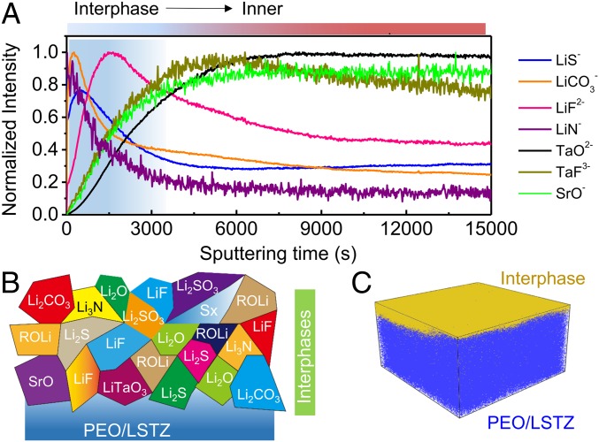
Time-of-flight secondary ion mass spectrometry (TOF-SIMS) depth profiling and mapping of the interphase on the cycled PEO/LSTZ membrane was conducted to further probe the chemical evolution and elemental distribution of the SEI formed in situ. The depth profiling in Fig. 5A shows a broad range of fragments of interest are detected on the cycled PEO/LSTZ, of which the Li-containing secondary ion fragments (LiS−, LiCO3−, LiF2−, and LiN−) represent the interphase while Ta/Sr-containing species (TaO2−, TaF3−, and SrO−) originate from the PEO/LSTZ electrolyte. The Li-containing fragments display obvious peak signals at the beginning of the sputtering time, but then the signals attenuate as the sputtering proceeds. In contrast, the detected signals of Ta/Sr-containing species initially appear weak, but increase over the entire sputtering time. The intensity evolution of the fragments in the cycled PEO/LSTZ demonstrates a layer of interphase covering the cycled PEO/LSTZ membrane. A depth profile of the pristine PEO/LSTZ membrane was also collected for comparison (SI Appendix, Fig. S9). All of the fragments of interest for the pristine PEO/LSTZ were somewhat more stable, but with lower intensities than those for cycled PEO/LSTZ during the whole sputtering time, which indicates that the detected species in the cycled PEO/LSTZ mainly come from the interface layer formed during cycling rather than from reaction products induced by the sputtering process. The interphase is composed of Li-containing species at the outer layer and transition-metal compounds in the inner layer close to the membrane electrolyte (Fig. 5B). The detection of transition-metal compounds indicates the LSTZ is involved in the formation of an interphase between the electrolyte and Li anode. A 3D view of the sputtered volume in Fig. 5C vividly visualizes the distribution of the interphase formation on the surface of PEO/LSTZ from the depth profile. On the basis of these in-depth TOF-SIMS and XPS analysis, we can conclude that an interphase layer composed of Li-containing species and Ta/Sr compounds was formed in situ at the Li-metal/electrolyte interface. The PEO and LiTFSI degrade during the lithium plating–stripping process to form LiF, Li2O, Li3N, Li2CO3, and Li2S (38, 39). On the other hand, the perovskite LSTZ reacts with lithium metal to form transition-metal compounds such as LiTaO3 and SrO. This interphase layer effectively improves the contact between the Li anode and the PEO/LSTZ electrolyte, promotes the wettability of the Li-metal anode, and suppresses the Li dendrite formation during repeated cycles.
Fig. 5.
(A) Normalized TOF-SIMS depth profiles of fragments of interest collected from a cycled PEO/LSTZ membrane. (B) Schematic illustration showing the chemical species of interest formed on the surface of the cycled PEO/LSTZ. (C) Corresponding 3D distribution of the interphase on the cycled PEO/LSTZ membrane.
All-Solid-State Li-Metal Batteries with PEO/LSTZ Composite.
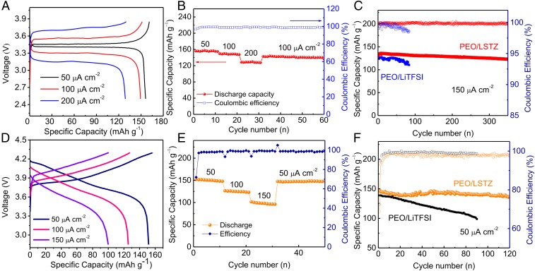
All-solid-state batteries with an LFP or a high-voltage NMC cathode, a PEO/LSTZ electrolyte, and a lithium anode were assembled to evaluate the feasibility of the PEO/LSTZ electrolyte for practical applications. The as-assembled LFP|PEO/LSTZ|Li solid-state battery had a total resistance of 430 Ω (SI Appendix, Fig. S10A), which is far smaller than those of other PEO-based batteries (27). Fig. 6A depicts the representative charge–discharge voltage profiles of the LFP solid-state battery at current densities of 50, 100, and 200 μA cm−2. All of the curves display clear, long, and flat voltage plateaus for the charge and discharge process, indicating a fast Li+ transfer through the PEO/LSTZ electrolyte and into the LFP cathode. In addition, the battery shows a low voltage gap of 0.06 V at 50 μA cm−2; even at a high density of 200 μA cm−2, the voltage gap remains less than 0.6 V. The solid-state LFP|PEO/LSTZ|Li battery also exhibits a good rate capability (Fig. 6B). High capacities of 156, 149, and 128 mAh g−1 are delivered at, respectively, 50, 100, and 200 μA cm−2. The capacity recovers to 143 mAh g−1 when the current returns to 100 μA cm−2. Further evaluation of the electrochemical and mechanical stability of the PEO/LSTZ membrane was performed with a long-term cycling test in an LFP|PEO/LSTZ|Li cell at 150 μA cm−2. As shown in Fig. 6C, a stabilized capacity of 136 mAh g−1 is delivered after an activation reaction in the first several cycles. After 350 cycles, the capacity remains at 123 mAh g−1 with a negligible capacity fade of 0.037 mAh g−1 per cycle. The Coulombic efficiency remains above 99.5% over the duration of cycling. In contrast, the cell with PEO/LiTFSI electrolyte can only run less than 100 cycles before dying.
Fig. 6.
Electrochemical performance of (A–C) LFP|PEO/LSTZ|Li and (D–F) NMC|PEO/LSTZ|Li cells tested at 45 °C. (A and D) Voltage profiles and corresponding (B and E) rate capability at various current densities, and (C and F) cycling stability and Coulombic efficiency.
The PEO/LSTZ electrolyte also shows promising capability of pairing with an NMC cathode for high-voltage all-solid-state batteries. Since PEO is not capable of withstanding oxidation at a high voltage (SI Appendix, Fig. S10B) (40), we replaced PEO by poly(vinylidene difluoride) (PVDF) in the NMC cathode to avoid exposing the PEO/LSTZ electrolyte to the high-voltage NMC cathode. SI Appendix, Fig. S10C shows that the NMC particles are uniformly covered by a PVDF binder, suggesting that the PEO/LSTZ electrolyte is well protected in the cell system. With such a protection strategy, the NMC|PEO/LSTZ|Li cells were charged to a high voltage up to 4.3 V with the characteristic voltage profiles of an NMC cathode (Fig. 6D) (41, 42). Rate capability results demonstrate that stabilized capacities of around 151, 125, and 100 mAh g−1 are delivered at 50, 100, 150 μA cm−2, respectively (Fig. 6E). The NMC|PEO/LSTZ|Li cell also exhibits a reasonable cycling performance with a capacity retention of 119 mAh g−1 at 50 μA cm−2 after 120 cycles, which corresponds to a retention of 81.5% of the highest discharge capacity (Fig. 6F). At present, such a long cycling performance has not been reported for an all-solid-state Li-metal battery with a PEO-based polymer electrolyte and a Ni-rich high-voltage cathode. The capacity loss on cycling is mainly attributed to the formation of a passivating layer at the NMC/PVDF interface as well as the volume contraction of the NMC particles during delithiation. This contraction would cause the NMC to lose contact with surrounding conductive carbon or PVDF binders during delithiation (43). In contrast, the NMC|PEO/LiTFSI|Li cell fades fast in capacity and delivers a poor cycle life. The all-solid-state Li|LFP and Li|NMC batteries with the PEO/LSTZ electrolyte exhibited a low capacity because of a low ionic conductivity of the electrolyte, a large electrode/electrolyte interfacial resistance, and a sluggish Li+ mobility in the cathode at 25 °C (SI Appendix, Fig. S11).
Conclusion
We report a flexible composite electrolyte membrane based on a PEO polymer and a perovskite LSTZ that delivers Li+ conductivities of 5.4 × 10⁻⁵ and 3.5 × 10⁻⁴ S cm−1 at 25 and 45 °C, respectively. XPS and DFT results reveal that the Ta5+ from the perovskite LSTZ bonds strongly with F− in the TFSI− anion, thus facilitating the release of Li ions from LiTFSI and significantly improving the Li+ conductivity. Symmetric lithium cells with this PEO/LSTZ electrolyte exhibit a stable, long-life Li stripping/plating behavior over 700 h without obvious lithium-dendrite growth. Moreover, the symmetric cell can be cycled at a high current density up to 0.6 mA cm−2 with a low overpotential of 310 mV, indicating a fast charge transfer and a stabilized interface between the PEO/LSTZ electrolyte and Li metal. LFP|PEO/LSTZ|Li and high-voltage NMC|PEO/LSTZ|Li solid-state batteries exhibit good performance with a high capacity and good rate capability. Surface analysis on the cycled electrolyte membrane proves that an interphase layer is formed in situ at the interface, which improves the contact between the Li anode and PEO/LSTZ electrolyte, promotes the wettability of the Li-metal anode, and suppresses the lithium-dendrite growth. The enhanced Li+ conductivity of the electrolyte membrane, an improved electrolyte/electrode interface, and a stable solid-state system all contribute to the excellent performance of a solid-state battery with a PEO/LSTZ electrolyte.
Materials and Methods
The PEO/LSTZ electrolyte membrane was prepared by drying a mixture of PEO, LiTFSI, LSTZ powders, and acetonitrile in a vacuum oven at 50 °C for 24 h. DFT calculations were performed with the Vienna Ab-initio Simulation Package. The surface chemical analysis of the PEO/LSTZ were performed with XPS and TOF-SIMS instruments. A symmetric Li|PEO/LSTZ|/Li cell was assembled by sandwiching a PEO/LSTZ membrane between two lithium discs. The Galvanostatic charge/discharge of the solid-state batteries was performed at 45 °C on a Land CT2001A battery-test system. More details on the materials and methods can be found in SI Appendix.
Supplementary Material
Acknowledgments
This work was supported by the Assistant Secretary for Energy Efficiency and Renewable Energy, Office of Vehicle Technologies of the US Department of Energy through the Advanced Battery Materials Research (BMR) Program (Battery500 Consortium) Award DE-EE0007762. Y. Li also acknowledges the funding support from Enpower Greentech LLC UTA17-001111. The theoretical calculations were supported by the Welch Foundation (Grant F-1959-20180324) and a startup grant from University of Texas at Austin (UT Austin) providing computational resources sponsored by the DOE’s Office of EERE located at the National Renewable Energy Laboratory and the Texas Advanced Computing Center at UT Austin. P.-H.C. and Y.-Y.H. acknowledge the financial support from National Science Foundation (NSF) under Grant DMR-1808517. All solid-state NMR experiments were performed at the National High Magnetic Field Laboratory. The National High Magnetic Field Laboratory is supported by NSF through NSF/DMR-1644779 and the State of Florida.
Footnotes
The authors declare no conflict of interest.
This article contains supporting information online at www.pnas.org/lookup/suppl/doi:10.1073/pnas.1907507116/-/DCSupplemental.
References
- 1.Liu W., et al. , Enhancing ionic conductivity in composite polymer electrolytes with well-aligned ceramic nanowires. Nat. Energy 2, 17035 (2017). [Google Scholar]
- 2.Goodenough J. B., Kim Y., Challenges for rechargeable Li batteries. Chem. Mater. 22, 587–603 (2010). [Google Scholar]
- 3.Dong T. T., et al. , A multifunctional polymer electrolyte enables ultra-long cycle-life in a high-voltage lithium metal battery. Energy Environ. Sci. 11, 1197–1203 (2018). [Google Scholar]
- 4.Xue Z. G., He D., Xie X. L., Poly(ethylene oxide)-based electrolytes for lithium-ion batteries. J. Mater. Chem. A 3, 19218–19253 (2015). [Google Scholar]
- 5.Lin D., et al. , A silica-aerogel-reinforced composite polymer electrolyte with high ionic conductivity and high modulus. Adv. Mater. 30, e1802661 (2018). [DOI] [PubMed] [Google Scholar]
- 6.Zhou H., Fedkiw P. S., Ionic conductivity of composite electrolytes based on oligo(ethylene oxide) and fumed oxides. Solid State Ion. 166, 275–293 (2004). [Google Scholar]
- 7.Lin D., et al. , High ionic conductivity of composite solid polymer electrolyte via in situ synthesis of monodispersed SiO2 nanospheres in poly(ethylene oxide). Nano Lett. 16, 459–465 (2016). [DOI] [PubMed] [Google Scholar]
- 8.Xu H., et al. , Li3N-Modified garnet electrolyte for all-solid-state lithium metal batteries operated at 40 °C. Nano Lett. 18, 7414–7418 (2018). [DOI] [PubMed] [Google Scholar]
- 9.Yang L., et al. , Flexible composite solid electrolyte facilitating highly stable “soft contacting” Li-electrolyte interface for solid state lithium-ion batteries. Adv. Energy Mater. 7, 1701437 (2017). [Google Scholar]
- 10.Zhang Z. H., et al. , An advanced construction strategy of all-solid-state lithium batteries with excellent interfacial compatibility and ultralong cycle life. J. Mater. Chem. A 5, 16984–16993 (2017). [Google Scholar]
- 11.Wang W. M., Yi E. Y., Fici A. J., Laine R. M., Kieffer J., Lithium ion conducting poly(ethylene oxide)-based solid electrolytes containing active or passive ceramic nanoparticles. J. Phys. Chem. C 121, 2563–2573 (2017). [Google Scholar]
- 12.Zhang X., et al. , Synergistic coupling between Li6.75La3Zr1.75Ta0.25O12 and poly(vinylidene fluoride) induces high ionic conductivity, mechanical strength, and thermal stability of solid composite electrolytes. J. Am. Chem. Soc. 139, 13779–13785 (2017). [DOI] [PubMed] [Google Scholar]
- 13.Liu W., et al. , Ionic conductivity enhancement of polymer electrolytes with ceramic nanowire fillers. Nano Lett. 15, 2740–2745 (2015). [DOI] [PubMed] [Google Scholar]
- 14.Zha W. P., Chen F., Yang D. J., Shen Q., Zhang L. M., High-performance Li6.4La3Zr1.4Ta0.6O12/Poly(ethylene oxide)/Succinonitrile composite electrolyte for solid-state lithium batteries. J. Power Sources 397, 87–94 (2018). [Google Scholar]
- 15.Fu K. K., et al. , Flexible, solid-state, ion-conducting membrane with 3D garnet nanofiber networks for lithium batteries. Proc. Natl. Acad. Sci. U.S.A. 113, 7094–7099 (2016). [DOI] [PMC free article] [PubMed] [Google Scholar]
- 16.Chen L., et al. , PEO/garnet composite electrolytes for solid-state lithium batteries: From “ceramic-in-polymer” to “polymer-in-ceramic”. Nano Energy 46, 176–184 (2018). [Google Scholar]
- 17.Wan Z., et al. , Low resistance-integrated all-solid-state battery achieved by Li7La3Zr2O12 nanowire upgrading polyethylene oxide (PEO) composite electrolyte and PEO cathode binder. Adv. Funct. Mater. 29, 1805301 (2019). [Google Scholar]
- 18.Chen F., et al. , Solid polymer electrolytes incorporating cubic Li7La3Zr2O12 for all-solid-state lithium rechargeable batteries. Electrochim. Acta 258, 1106–1114 (2017). [Google Scholar]
- 19.Jiang Z. Y., et al. , Perovskite membranes with vertically aligned microchannels for all-solid-state lithium batteries. Adv. Energy Mater. 8, 1801433 (2018). [Google Scholar]
- 20.Xie H., et al. , Flexible, scalable, and highly conductive garnet-polymer solid electrolyte templated by bacterial cellulose. Adv. Energy Mater. 8, 1703474 (2018). [Google Scholar]
- 21.Tao X., et al. , Solid-state lithium-sulfur batteries operated at 37 °C with composites of nanostructured Li7La3Zr2O12/carbon foam and polymer. Nano Lett. 17, 2967–2972 (2017). [DOI] [PubMed] [Google Scholar]
- 22.Zhao C. Z., et al. , An anion-immobilized composite electrolyte for dendrite-free lithium metal anodes. Proc. Natl. Acad. Sci. U.S.A. 114, 11069–11074 (2017). [DOI] [PMC free article] [PubMed] [Google Scholar]
- 23.Li Y., et al. , A perovskite electrolyte that is stable in moist air for lithium-ion batteries. Angew. Chem. Int. Ed. Engl. 57, 8587–8591 (2018). [DOI] [PubMed] [Google Scholar]
- 24.Borodin O., Smith G. D., Mechanism of ion transport in amorphous poly(ethylene oxide)/LiTFSI from molecular dynamics simulations. Macromolecules 39, 1620–1629 (2006). [Google Scholar]
- 25.Zhai H., et al. , A flexible solid composite electrolyte with vertically aligned and connected ion-conducting nanoparticles for lithium batteries. Nano Lett. 17, 3182–3187 (2017). [DOI] [PubMed] [Google Scholar]
- 26.Lin Y., et al. , Biocompatible and biodegradable solid polymer electrolytes for high voltage and high temperature lithium batteries. RSC Adv. 7, 24856–24863 (2017). [Google Scholar]
- 27.Sheng O., et al. , Mg2B2O5 nanowire enabled multifunctional solid-state electrolytes with high ionic conductivity, excellent mechanical properties, and flame-retardant performance. Nano Lett. 18, 3104–3112 (2018). [DOI] [PubMed] [Google Scholar]
- 28.Zheng J., Hu Y. Y., New insights into the compositional dependence of Li-ion transport in polymer-ceramic composite electrolytes. ACS Appl. Mater. Interfaces 10, 4113–4120 (2018). [DOI] [PubMed] [Google Scholar]
- 29.Zheng J., Dang H., Feng X., Chien P.-H., Hu Y.-Y., Li-ion transport in a representative ceramic–polymer–plasticizer composite electrolyte: Li7La3Zr2O12–polyethylene oxide–tetraethylene glycol dimethyl ether. J. Mater. Chem. A 5, 18457–18463 (2017). [Google Scholar]
- 30.Zheng J., Tang M., Hu Y. Y., Lithium ion pathway within Li7 La3 Zr2 O12 -polyethylene oxide composite electrolytes. Angew. Chem. Int. Ed. Engl. 55, 12538–12542 (2016). [DOI] [PubMed] [Google Scholar]
- 31.Li Y., et al. , Hybrid polymer/garnet electrolyte with a small interfacial resistance for lithium-ion batteries. Angew. Chem. Int. Ed. Engl. 56, 753–756 (2017). [DOI] [PubMed] [Google Scholar]
- 32.Fan X., et al. , Fluorinated solid electrolyte interphase enables highly reversible solid-state Li metal battery. Sci. Adv. 4, eaau9245 (2018). [DOI] [PMC free article] [PubMed] [Google Scholar]
- 33.Zheng B., et al. , Stabilizing Li10SnP2S12/Li interface via an in situ formed solid electrolyte interphase layer. ACS Appl. Mater. Interfaces 10, 25473–25482 (2018). [DOI] [PubMed] [Google Scholar]
- 34.Li N. W., et al. , A flexible solid electrolyte interphase layer for long-life lithium metal anodes. Angew. Chem. Int. Ed. Engl. 57, 1505–1509 (2018). [DOI] [PubMed] [Google Scholar]
- 35.Xu H., Wang S., Manthiram A., Hybrid lithium-sulfur batteries with an advanced gel cathode and stabilized lithium-metal anode. Adv. Energy Mater. 8, 1800813 (2018). [Google Scholar]
- 36.Sun B., et al. , At the polymer electrolyte interfaces: The role of the polymer host in interphase layer formation in Li-batteries. J. Mater. Chem. A 3, 13994–14000 (2015). [Google Scholar]
- 37.Eshetu G. G., et al. , Ultrahigh performance all solid-state lithium sulfur batteries: Salt anion’s chemistry-induced anomalous synergistic effect. J. Am. Chem. Soc. 140, 9921–9933 (2018). [DOI] [PubMed] [Google Scholar]
- 38.Xu C., et al. , Interface layer formation in solid polymer electrolyte lithium batteries: An XPS study. J. Mater. Chem. A 2, 7256–7264 (2014). [Google Scholar]
- 39.Aurbach D., et al. , Recent studies on the correlation between surface chemistry, morphology, three-dimensional structures and performance of Li and Li-C intercalation anodes in several important electrolyte systems. J. Power Sources 68, 91–98 (1997). [Google Scholar]
- 40.Kitazawa Y., et al. , Polymer electrolytes containing solvate ionic liquids: A new approach to achieve high ionic conductivity, thermal stability, and a wide potential window. Chem. Mater. 30, 252–261 (2018). [Google Scholar]
- 41.Jung R., Metzger M., Maglia F., Stinner C., Gasteiger H. A., Oxygen release and its effect on the cycling stability of LiNixMnyCozO2 (NMC) cathode materials for Li-ion batteries. J. Electrochem. Soc. 164, A1361–A1377 (2017). [Google Scholar]
- 42.Yao P., et al. , PVDF/Palygorskite nanowire composite electrolyte for 4 V rechargeable lithium batteries with high energy density. Nano Lett. 18, 6113–6120 (2018). [DOI] [PubMed] [Google Scholar]
- 43.Koerver R., et al. , Capacity fade in solid-state batteries: Interphase formation and chemomechanical processes in nickel-rich layered oxide cathodes and lithium thiophosphate solid electrolytes. Chem. Mater. 29, 5574–5582 (2017). [Google Scholar]
Associated Data
This section collects any data citations, data availability statements, or supplementary materials included in this article.


