Abstract
This paper presents an implantable wireless battery recharging system design for bladder pressure chronic monitoring. The wireless recharging system consists of an external 15 cm-diameter 6-turn powering coil and a silicone-encapsulated implantable rectangular coil with a dimension of 7 mm × 17 mm × 2.5 mm and 18 turns, which further encloses a 3 mm-diameter and 12 mm-long rechargeable battery, two ferrite rods, an ASIC, and a tuning capacitor. For a constant recharging current of 100 μA, an RF power of 700 μW needs to be coupled into the implantable module through the tuned coils. Analyses and experiments confirm that with the two coils aligned coaxially or with a 6 cm axial offset and a tilting angle of 30°, an external power of 3.5 W or 10 W is required, respectively, at an optimal frequency of 3 MHz to cover a large implant depth of 20 cm.
Introduction
Urinary incontinence is a severe medical symptom caused by spinal injury, aging and various medical conditions, which affects more than half the population above age of sixty. Conventional urodynamics diagnose based on urethral catheter insertion for short-term bladder pressure monitoring is inconvenient and unreliable.1–3 It is, therefore, highly desirable to develop a wireless implantable bladder pressure sensor, which can chronically monitor the bladder pressure, followed by wireless data transmission to an external receiver for analysis and ultimately feedback control through functional electrical stimulation.4,5
Implant studies reveal that foreign objects chronically located within the lumen of the bladder are subject to mineral encrustation such as stone formation, and also may be expelled during urination. The proposed wireless implantable bladder pressure sensor is intended to be inserted into the bladder using conventional urological tools, for example a cystoscope, and implanted in the bladder wall.6 A hollow insertion tool can use its sharp point to pierce the mucosa and create a small pocket in the submucosal area next to the muscle. An implanted device can be held in this space by the mucosa, which exhibits a sufficient mechanical strength to retain the implant.6 The pressure measured through the urothelium can be calibrated to account for attenuation from the tissue.7 Once the bladder heals, the implant remains in a secure location that is out of the urine stream, thus reducing the chance of stone formation.
Wireless implantable pressure sensors, in particular blood pressure sensors, have been extensively investigated and demonstrated, for example micromachined pressure sensors implanted in the excluded space of human stent-graft-repaired abdominal arotic aneurysms as well as in the pulmonary artery for a real-time monitoring of local pressure.8–10 MEMS pressures incorporated inside a miniature flexible sensing cuff wrapped around laboratory animals’ abdominal aortic and carotid arteries to capture blood pressure waves from free roaming rodents and mice have been developed for life science research.11–13
Most of the wireless implantable pressure sensors do not contain batteries. Instead, the systems rely on external radio frequency (RF) energy sources for a passive sensing8–10 or an active sensing employing signal acquisition, processing and data telemetry means.11–13 Inductively-coupled techniques have been widely used as an effective RF power transfer means for various wireless sensing applications.8–27 Recently, multi-coils-based coupling systems were demonstrated to achieve an enhanced RF coupling efficiency.28,29 Ultrasonic techniques were also proposed as an alternative to deliver power for deep implant applications30–32 but calling for a careful impedance match with the skin and surround tissues.
While battery-less operation is attractive for realizing highly miniaturized implant systems, it exhibits one key constraint, i.e. an external RF power source needs to be available for an implant to function. This presents a severe inconvenience for a number of human implant applications, for example the proposed implantable bladder pressure chronic monitoring application, which demands a constant ambulatory monitoring capability; therefore requiring an implantable battery as a critical component for the overall system design.
Advancement in battery technology over the past decade has achieved miniaturized and reliable rechargeable batteries with adequate power density.33 For instance, rechargeable Liion QL-0003I battery (from Quallion LLC) exhibiting a small volume of 0.08 cm3 can provide a capacity of 3 mA h with a typical recharging cycle of 3000 times without significant performance degradation. With a daily recharging, the battery can be implanted in patient for approximately ten years. An efficient RF recharging capability is, therefore, highly crucial for the proposed overall implant system design. Inductively-coupled power transfer techniques can cover a short coupling distance typically ranging from a few millimeters to a few centimeters.8–29 However, in the proposed application, depending on individual patient’s size and weight a large power coupling distance between 10 cm to 20 cm may be required, thus imposing a significant design challenge for achieving an optimal and efficient power coupling. This paper presents the development of a wireless implantable RF-based battery recharging system. The entire implantable system design, implementation, and demonstration for treating urinary incontinence based on bladder pressure sensing, wireless data telemetry, RF power recharging, sensor data processing, and closed-loop feedback control will be planned and performed as future work. Section II describes the overall wireless implantable bladder pressure sensing system. Section III illustrates the proposed wireless battery recharging system architecture with key RF components characterization and system design optimization. Section IV presents the recharging control electronics design. Section V shows the prototype system measurement results with conclusions given in section VI.
Wireless implantable bladder pressure sensing system
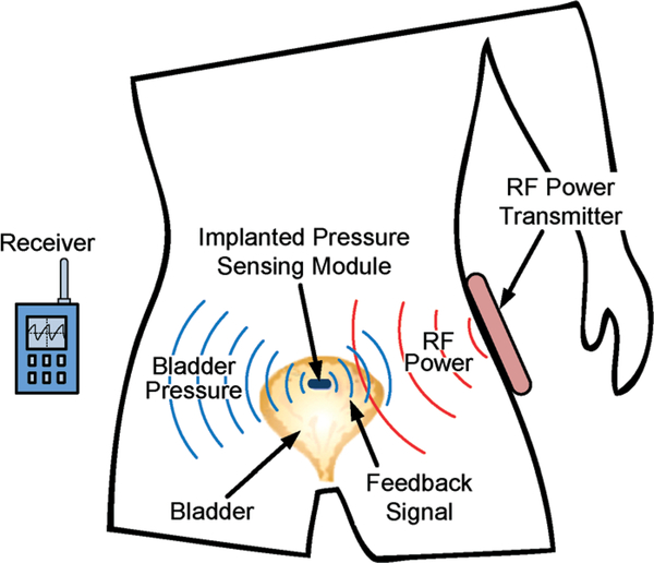
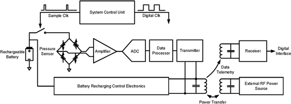
Fig. 1 presents the proposed wireless implantable bladder pressure sensing system architecture, where a pressure sensing module is implanted under the bladder mucosa layer and can wirelessly transmit the bladder pressure information to an external receiver for analysis and ultimately feedback control through functional electrical stimulation, thus providing an effective treatment for urinary incontinence. An external RF power transmitter can be attached to a patient’s body, as depicted in the figure, to deliver RF power to recharge a rechargeable battery employed as a part of the pressure sensing module. The recharging procedure can be performed once a day, for example during the patient’s sleeping time at night, thus greatly improving user convenience and enabling a constant ambulatory monitoring capability. Fig. 2 illustrates the key electrical building blocks required to design and implement the proposed wireless implantable system. The system consists of two main functions: (1) bladder pressure sensing with wireless data telemetry, and (2) RF-based battery power recharging. As depicted in Fig. 2, a MEMS piezoresistive pressure sensor will be employed to detect the bladder pressure followed by a front-end amplifier and an analogy-to-digital converter (ADC). The digitized pressure information will be processed by a data processor for frame alignment as well as encoding prior to wireless data telemetry to an external receiver. A system control unit can further operate the implant in a duty-cycled manner to minimize power dissipation. An external RF power source can inductively couple the RF energy into the implantable system, interfaced by the battery recharging control electronics to properly recharge the battery. The RF-based battery power recharging system design and characterization are the focus of this paper, which will be described in detail in the subsequent sections.
Fig. 1.
Wireless implantable bladder pressure sensing system architecture.
Fig. 2.
Electrical system design topology for wireless implantable bladder pressure sensor.
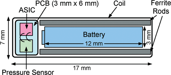
The proposed wireless implantable bladder pressure sensor will be implanted by using a standard surgical cystoscope, which can accommodate a packaged implant with a dimension of approximately 5 mm × 9 mm × 18 mm.6 Fig. 3 depicts the layout of the proposed wireless implantable sensor, consisting of a rectangular RF coil exhibiting a lateral dimension of 7 mm × 17 mm and a height of 2.5 mm with 18 turns, which further encloses an application specific integrated circuit (ASIC), a MEMS pressure sensor, a rechargeable battery with a 3 mm diameter and a 12 mm length, and two ferrite rods placed adjacent to the battery. The ferrite rods are employed to improve the coil quality factor as a critical parameter to enhance RF power coupling efficiency. The coil dimension is chosen to maximize its inductive coupling factor with respect to an external RF powering coil, as will be described in the following section.
Fig. 3.
Layout of wireless implantable bladder pressure sensor design.
Wireless RF-based battery recharging system
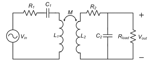
Fig. 4 presents the design architecture of the RF-based battery recharging system. An RF power is coupled to the implanted coil, L2, from an external coil, L1, tuned to the same frequency through mutual inductance. The received RF power, which exhibits an AC voltage swing at Vout, is then rectified and filtered to produce a DC voltage at V’out to recharge a rechargeable battery through the recharging control electronics shown in the figure.
Fig. 4.
Wireless RF-based battery recharging system design architecture.
In the prototype system design, a 15 cm-diameter coil with an optimal number of turns is employed as the external powering coil. The coil dimension is chosen to be suitable for future implementation as a part of a wearable unit. It is challenging to achieve a high DC supply voltage for the implant via RF powering over a large distance between 10 cm to 20 cm without consuming an excessively large external power. Therefore, a CMOS voltage doubler is chosen to implement the rectifier to reduce the voltage gain requirement compared to full-wave rectifier and half-wave rectifier counterparts. Typically, a constant current mode recharging followed by a constant voltage mode recharging is required to fully recharge a battery. However, it can be shown that a full battery recharge is not necessary for the consideration of increasing the battery recharging cycles. Therefore, a constant current recharging scheme is chosen for the proposed application to charge up the battery to a few hundred millivolts below the maximum allowed battery voltage. In addition, the constant current mode recharging results in an approximately constant impedance presented to the LC tank in the implantable system, which is desirable for achieving a stable optimal RF power coupling efficiency. It should be noted that in the prototype design, a constant recharging current of 100 μA is selected as a sufficient level to replenish the battery once a day.
It is critical to design an efficient and optimized front-end RF power coupling system in order to enhance the overall system performance. Fig. 5 present a simplified front-end inductively-coupled RF power transfer system. It can be shown that the voltage gain, Av, from Vin to Vout can be expressed as:26,27
where M is the mutual inductance between the external coil of L1 and implantable coil of L2, ω is the tuned resonant frequency of two coils, R1 and R2 are the series resistances associated with L1 and L2, respectively, and Rload is the load resistance of the CMOS rectifier presented to the tuned implantable coil. Further simplifying the equation results in the following expression:
where k is the coupling factor between L1 and L2, Q1 and Q2 are the loaded quality factor of the external coil and unloaded quality factor of the implantable coil, respectively, and β is the ratio between an equivalent serial load resistance of presented to the implantable coil and the coil’s intrinsic serial resistance of R2, which can be expressed as . The power coupling efficiency, defined as the ratio of the power delivered into the CMOS rectifier and the power dissipated in the external tuned coil loop, under a weak coupling condition can be further derived as
Fig. 5.
Inductively-coupled RF power transfer system.
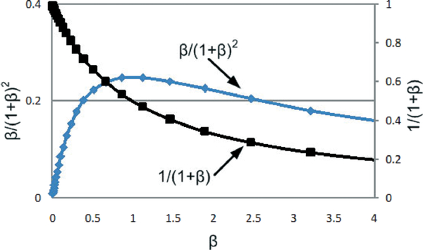
From the above equations, it is evident that improving inductive coupling factor and coils quality factors can directly enhance the voltage gain as well as the power coupling efficiency. Moreover, β plays in a critical role in performance. Fig. 6 plots the terms of 1/1 + β and β /(1 + β)2 versus β, indicating (1) for a small β, a large voltage gain can be obtained, however with a penalty of a reduced power coupling efficiency, and (2) for a large β both gain and efficiency will be degraded. An optimal condition as a trade-off between voltage gain and efficiency occurs around β = 1, which represents a power impedance matching between Rload and an equivalent parallel resistance due to R2 at the tuned resonant frequency. In other words, given L2, R2, and Rload, an optimal operating frequency can be selected to maximize the power coupling efficiency, provided that the chosen frequency is well below the coil self-resonance. It should be noted that the terms of 1/1 + β and β /(1 + β)2 exhibit a variation within 10% for β between 0.5 and 1.5.
Fig. 6.
Voltage gain and power coupling efficiency characteristic curves versus β.
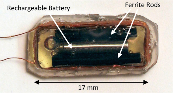
A prototype implantable coil with dimensions described in Fig. 3 was constructed and encapsulated by a silicone layer, as shown in Fig. 7, to characterize the coupling factor, k, with respect to a number of external RF powering coils, exhibiting a diameter ranging from 10 cm to 20 cm. The implantable coil encloses a rechargeable battery and two ferrite rods. For simplicity of the coupling characterization, pressure sensor and ASIC were not included in this packaged module.
Fig. 7.
Silicone-encapsulated implantable coil enclosing battery and ferrite rods.
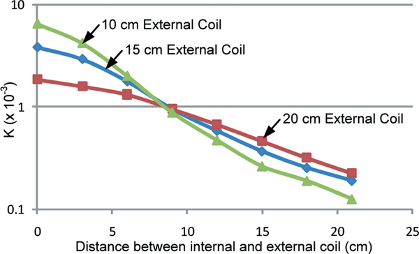
Fig. 8 presents the measured coupling factor as a function of gap size between the coils under an axially aligned configuration, indicating that (1) a larger k factor can be achieved with the 10 cm-diameter external coil for a separation distance below 8 cm, and (2) at large separation distance, a 20 cm-diameter external coil can yield a higher coupling factor. Therefore, a 15 cm-diameter external coil was chosen as a compromise for the prototype design.
Fig. 8.
Measured coupling factor between an implantable coil and external coils as a function of gap size between the coils.
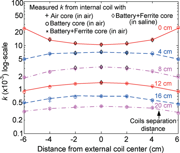
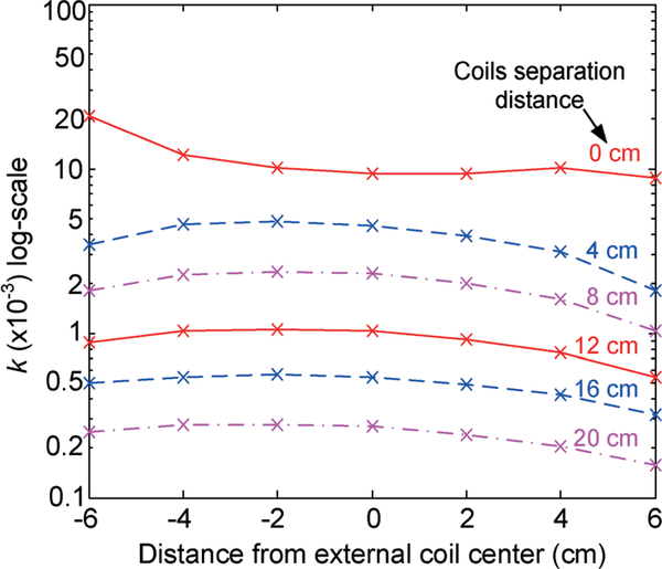
The inductive coupling factor between the silicone-encapsulated implantable coil and 15 cm-diameter external coil was then further characterized as a function of gap size between the two coils, and lateral position as well as tilting angle of the implantable coil with respect to the external coil. Fig. 9 shows the measured inductive coupling factor as a function of coils gap size and lateral position of the implantable coil with respect to the external coil while maintaining a 0-degree tilting angle. As shown in the plot, the k factor varies from 0.3 × 10⁻³ to 0.4 × 10⁻³ with a 20 cm distance between the two coils, whereas at the gap size of 8 cm, the k factor varies from 1.9 × 10⁻³ along the external coil edge to 3.2 × 10⁻³ at the external coil center. It should be noted that the coupling factor is only a function of coils geometry and their relative position, and is independent of materials, for example battery and ferrite rods enclosed in the middle of the implantable coil, and testing medium such as air and saline solution. Characterization results with a 30° of tilting angle between the coils, as shown in Fig. 10, reveal that the k factor varies from 0.2 × 10⁻³ to 0.3 × 10⁻³ with a 20 cm distance between the two coils, whereas at the gap size of 8 cm, the k factor varies from 1 × 10⁻³ along the external coil edge to 2.3 × 10⁻³ at the external coil center due to the direction of the magnetic flux with respect to the coils plane. To minimize the coupling factor variation due to coil tilting, it is envisioned that a number of external coils can be employed with overlapped regions in future system designs.
Fig. 9.
Measured coupling factor between implantable coil (under different core and testing medium conditions) and 15 cm-diameter external coil as a function of coils gap size and lateral position with a 0-degree tilting angle.
Fig. 10.
Measured coupling factor between implantable coil (under different core and testing medium conditions) and 15 cm-diameter external coil as a function of coils gap size and lateral position with a 30-degree tilting angle.
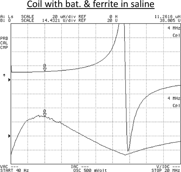
Besides characterizing inductive coupling factor between the proposed implantable coil and external RF powering coil, quality factor (Q-factor) and inductance value of the coils were also extensively characterized in order to achieve an optimized design condition with a predictable system performance. The implantable coil was characterized in saline solution emulating an in vivo environment. Fig. 11 presents the measured inductance value and quality factor as a function of frequency, revealing an inductance value of approximately 11 μH below 4 MHz, a maximum quality factor of 40 at 3 MHz, and a self-resonance around 13 MHz. Additional measurement data indicates that (1) insertion of battery in the coil degrades the coil quality factor by approximately 50% while maintaining a nearly constant inductance value due to the loss incurred by the battery; (2) insertion of battery with ferrite rods results in a quality factor reduction of about only 10% while increasing the inductance value by 30%, indicating an intended inductance enhancement effect due to the ferrite rods; (3) silicone package introduces an negligible effect; and (4) testing in saline solution causes a quality factor drop by 20% due to energy dissipation in the conductive medium compared to the performance data obtained in air.
Fig. 11.
Measured inductance value and quality factor of silicone-encapsulated implantable coil enclosing a rechargeable battery and two ferrite rods immersed in saline solution.
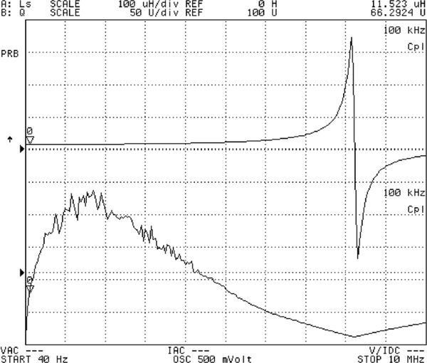
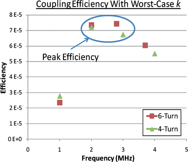
An external RF powering coil exhibiting a diameter of 15 cm and 6 turns was also characterized for its inductance value and quality factor. Fig. 12 presents the characterization results indicating an inductance value of approximately 11.5 μH below 5 MHz, a maximum quality factor of 230 at 2 MHz, and a self-resonance at 8.5 MHz. For a constant recharging current of 100 μA, which is adequate for the proposed implantable application, it can be shown that an RF power of approximately 700 μW needs to be coupled into the implantable system through the tuned coil loops with an equivalent loading resistance, Rload, of 7.5 kΩ. Based on the coils characterization results, Fig. 13 presents a calculated power coupling efficiency under the lowest coupling condition versus frequency, indicating a peak efficiency of 7.5 × 10⁻⁵ can be achieved at an optimal frequency of 3 MHz for a 6-turn external coil. As a comparison, a 4-turn external coil is also used to show an optimal frequency of 2 MHz with an efficiency slightly above 7 × 10⁻⁵ as depicted in the figure. It should be noted that the optimal operating frequencies result in a corresponding β value of unity, thus confirming the design optimization. External coils with a higher number of turns are not considered in the design due to their low self-resonant frequency.
Fig. 12.
Measured inductance value and quality factor of external RF powering coil.
Fig. 13.
Power coupling efficiency under worst-case coupling condition employing 4-turn and 6-turn external powering coils.
Fig. 14 presents the calculated worst-case external power requirement as function of coils gap size and tilting angle. As illustrated in the plot, an external RF power of 7 W is needed for a coils gap size of 20 cm with 0° tilting angle and 28 W for the same distance with 30° tilting angle. As mentioned previously, a number of overlapped external coils can be considered in future designs to minimize the coupling factor variation; hence, the external power requirement variation due to coils tilting. In addition, RF power level sensing inside the implant with an adaptive feedback and control of external RF power can be also incorporated in the design to minimize external power dissipation and ensure a reliable implant operation.34
Fig. 14.
Required external power versus distance under worst-case coupling conditions.
Recharging control electronics design
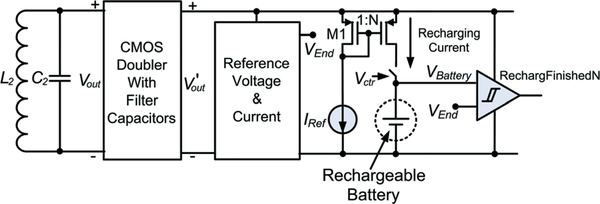
Recharging control electronics are critical components in the overall system design to ensure a proper recharging operation. Fig. 15 presents the integrated CMOS recharging control electronics design architecture, where a CMOS voltage doubler together with filter capacitors is implemented to realize a front-end voltage rectifier26 to convert an AC voltage signal with an amplitude of approximately 3.2 V across the LC tank to a DC voltage of around 4.5 V at V’out. This DC voltage further energizes the remaining electronic building blocks including (1) a band-gap-based reference voltage and current generator producing VEnd and IRef, (2) a 3-bit scalable recharging current source ranging from 30 μA to 250 μA for system design flexibility, and (3) logic control circuits that compare the rechargeable battery voltage to VEnd. The by disconnecting the battery from the recharging electronics.
Fig. 15.
Integrated CMOS recharging control electronics design architecture.
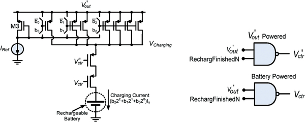
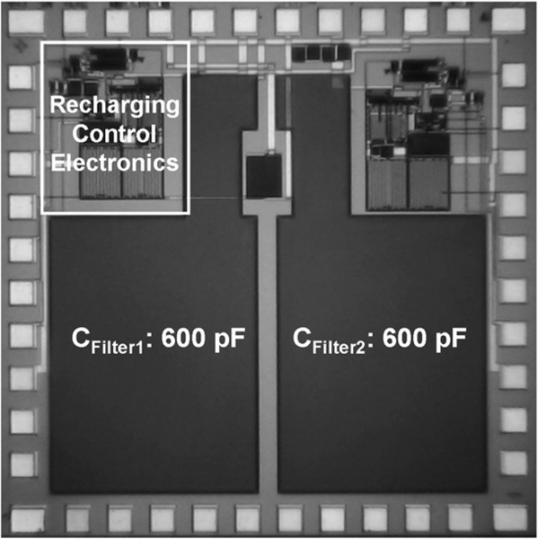
The switch controlled by Vctr shown in Fig. 15 requires a special design consideration in the proposed application. A PMOSFET is used to implement the switch to accommodate a low supply voltage. Turning off this device calls for Vctr to be high. However, due to a potential excessive input RF power, V’out can be much higher than Vctr, generated by the rechargeable battery, thus preventing the switch from being turned off. Therefore, a two-switch configuration is designed to ensure a proper operation as shown in Fig. 16, where Vctr and V’ctr are generated by the rechargeable battery and V’out, respectively. The two-switch control configuration reveals that (1) under a large V’out, turning off the switch controlled by V’ctr will be ensured; and (2) when the external RF power is turned off after the completion of recharging, the switch controlled by Vctr will be off to prevent a potential battery discharging to the ground. The recharging control electronics design was optimized in computer simulation and fabricated by using a commercial CMOS process. Fig. 17 presents the micrograph of a fabricated 2 mm × 2 mm ASIC, containing rectification, scalable charging current source, and logic control capability. It should be noted that the majority of the ASIC area is occupied by two 600 pF filter capacitors employed inside the CMOS voltage doubler circuit for ripple smoothing, and a second set of the recharging control electronics was also co-fabricated.
Fig. 16.
Two-switch control configuration for proper charging operation.
Fig. 17.
Micrograph of fabricated recharging control electronics.
Measurement results
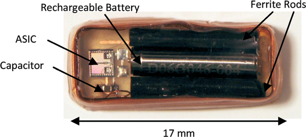
A prototype wireless implantable battery recharging system was implemented. Fig. 18 presents a photo of a silicone-encapsulated module consisting of an implantable coil that encloses a rechargeable battery, two ferrite rods, an ASIC, and a tuning capacitor at the center. The remaining space will be occupied by a pressure sensor and other necessary discrete components for future wireless implantable bladder sensor design. Silicone encapsulation was chosen for the prototype short-term in vitro testing. More robust packaging scheme such glass hematic encapsulation and multiple polymer layers coating35 will be considered for future long-term in vivo application.
Fig. 18.
Silicone-encapsulated wireless battery recharging module.
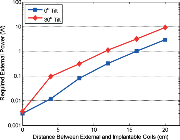
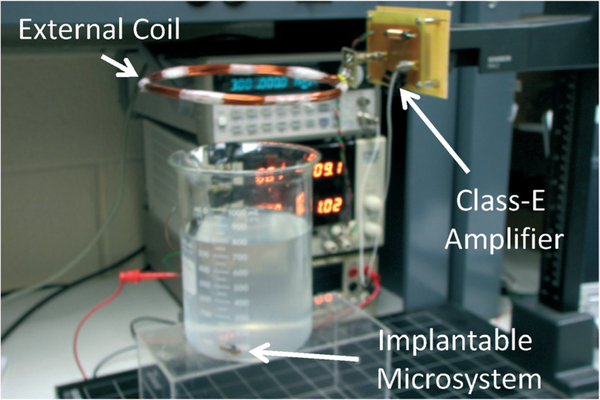
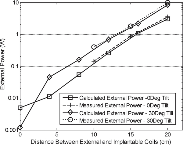
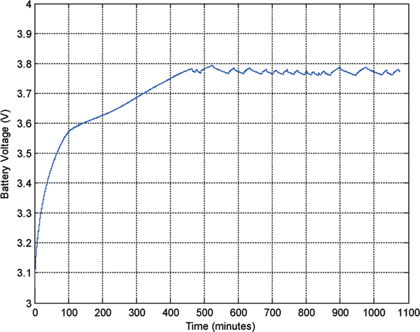
The prototype system was then characterized for its RF power coupling and battery recharging performance with an external powering coil. Fig. 19 presents a photo of the experimental setup. The wireless implantable battery recharging module is immersed in saline solution to emulate an in vivo environment. An external powering coil is placed above the module with its position being controlled vertically by a manipulator. A Class-E power amplifier drives the external coil at 3 MHz to couple RF power to the battery recharging system. Fig. 20 presents the measured external power level required for the battery recharging as function of coils distance and tilting angles. From the plot it can be seen that the measurement results are closely matched to the analytical prediction, thus further verifying the system design optimization. The battery recharging characteristics measured over 18 hours are shown in Fig. 21. The recharging electronics were first supplied by a 4.5 V DC battery and delivered a maximum output current of 250 μA while the battery was loaded with a 39 kΩ resistor; hence setting up a condition of having a loading current of approximately 100 μA and a battery recharging current of approximately 150 μA. It took 7.5 hours to fully charge the battery, reaching approximately 3.79 V as shown in the figure. Based on the designed logic control, the recharging process would end at this point. However, the battery voltage would exhibit a degradation over time due to the loading current. Once the battery voltage was dropped to around 3.76 V, the recharging process would be activated again. This behavior was repeatedly observed during the subsequent 10 hours of testing period.
Fig. 19.
Prototype experimental setup.
Fig. 20.
Measured external power versus distance.
Fig. 21.
Battery recharging characteristics under DC supply.
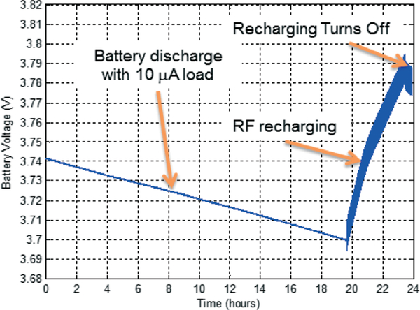
The prototype battery recharging system was then characterized under wireless powering condition. The battery was first discharged by a discharging current of 10 μA over 20 hours reaching a voltage of 3.7 V as shown in Fig. 22. At this point, a 3 MHz RF power source was activated to charge up the battery from 3.7 V to 3.79 V within approximately 4 hours under a recharging current of 100 μA, followed by battery discharge due to the loading current once the recharging process was turned off. A 3 MHz interference signal with a peak-to-peak amplitude of 40 mV was observed on the battery voltage due to high-frequency coupling.
Fig. 22.
Battery recharging characteristics under wireless powering.
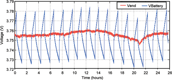
Careful observation of the measured waveform reveals that the battery recharging starting point and ending point can vary over time as well as the voltage difference between the starting and ending points. Additional experiments were conducted to verify that the variation of the voltage difference between the recharging starting and ending points was caused by noise coupling due to the cable connecting the battery to the measurement apparatus. Employing proper filtering techniques can greatly suppress such noise coupling. Furthermore, under an implant situation connecting cable will not be required, thus eliminating this noise coupling mechanism. The variation of the recharging starting point and ending point over time was due to the temperature dependence of VEnd. Analysis shows that VEnd in the prototype design exhibits a temperature sensitivity of approximately 12 mV °C−1. Fig. 23 illustrates the measured battery voltage recharging and discharging characteristics along with VEnd over 24 hours. The measured plot shows an evident correlation between VEnd and battery recharging and discharging characteristics. It is expected that the testing laboratory ambient temperature changes around 1 °C over 24 hours, thus resulting in a slow drift of VEnd around 15 mV.
Fig. 23.
Drift of battery charging characteristics with VEnd over 24 hours.
It should be noted that careful attention needs to be devoted to robust implant package design for long-term in vivo applications. Body fluid leakage through package would degrade the performance of electronics. Leakage and tissue growth encapsulating the implant package can alter the implantable coil inductance value, resulting in a detuned power coupling system; hence a degraded efficiency. High-Q power coupling systems are highly susceptible to such effects. Advanced design techniques based on power level sensing, optimal frequency scanning, and feedback control will be required to maintain system performance.
Conclusions
An optimized implantable wireless battery recharging system for bladder pressure chronic monitoring is presented. The wireless recharging system consists of an external 15 cm-diameter 6-turn powering coil and a silicone-encapsulated implantable rectangular coil exhibiting a dimension of 7 mm × 17 mm × 2.5 mm and 18 turns, which further encloses an ASIC, a 3 mm-diameter 12 mm-long rechargeable battery, and two ferrite rods. The ferrite rods are employed as critical components to enhance a high quality for the implantable coil to achieve a maximum power coupling efficiency at an optimal frequency. The prototype system successfully demonstrates the capability of coupling a required 700 μW power into the implantable module from an external 10 W RF power covering a large implant depth of 20 cm under the worst-case coupling condition. Characterization of the recharging control electronics also demonstrates the full design functionalities.
Acknowledgements
This work was supported in part by the Rehabilitation Research & Development Service of the Department of Veteran Affairs.
References
- 1.Gupta A, Defreitas G and Lemack GE, The reproducibility of urodynamic findings in healthy female volunteers: resulsts of repeated studies in the same setting and after short-tem follow-up, Neurourol. Urodyn, 2004, 23, 311–316. [DOI] [PubMed] [Google Scholar]
- 2.Rovner ES and Wein AJ, Evaluation of lower urinary tract symptoms in females, Curr. Opin. Neurol, 2003, 13, 273–278. [DOI] [PubMed] [Google Scholar]
- 3.Scaldazza CV and Morosetti C, Effect of different sized transurethral cathers on pressure-flow studies in women with lower urinary tract symptoms, Urol. Int., 2005, 75, 21–25. [DOI] [PubMed] [Google Scholar]
- 4.Jezernik S, Craggs MD, Grill WM, Creasey GH and Rijkhoff NJM, Electrical stimulation for the treatment of bladder dysfunction: Current status and future possibilities, Neurol. Res, 2002, 24, 413–430. [DOI] [PubMed] [Google Scholar]
- 5.Yoo PB and Grill WM, Minimally-invasive electrical stimulation of the pudental nerve: A pre-clinical study for neural control of the lower urinary tract, Neurourol. Urodyn., 2007, 26, 562–569. [DOI] [PubMed] [Google Scholar]
- 6.Fletter PC, Majerus S, Cong P, Damaser MS, Ko WH, Young DJ and Garverick SL, Wireless Micromanometer System for Chronic Bladder Pressure Monitoring, the 6th International Conference on Networked Sensing System, 2009, pp. 228–231. [Google Scholar]
- 7.Fletter PC, Zaszczurynski PJ and Damaser MS, Urothelial Biomechanics: Submucosal Sensing of Intravesical Pressure, in Proc. ASME 2008 Summer Bioengineering Conference, Marco Island, FL, 2008, pp. 25–29. [Google Scholar]
- 8.Allen MG, Micromachined Endovascularly Implantable Wireless Pressure Sensors: From Concept to Clinic, Proc. Transducers ‘05, 2005, pp. 275–278. [Google Scholar]
- 9.Fonseca MA, Kroh J, White J and Allen MG, Flexible wireless passive pressure sensors for biomedical applications, Solid-State Sensor, Actuator,and Microsystems Workshop, 2006, pp. 37–42. [Google Scholar]
- 10.Allen MG, Microfabricated Implantable Wireless Microsystems: Permanent And Biodegradable Implmentations, Technical Digest, The 27th IEEE International Conference on Micro Electro Mechanical Systems, San Francisco, California, 2014, pp. 1–4. [Google Scholar]
- 11.Cong P, Chaimanonart N, Ko WH and Young DJ, A Wireless and Batteryless 130 milligram 300 μW 10-bit Implantable Blood Pressure Sensing Microsystem for Real-time Genetically Engineered Mice Monitoring, IEEE International Solid-State Circuits Conference (ISSCC), San Francisco, 2009, pp. 428–429. [Google Scholar]
- 12.Cong P, Chaimanonart N, Ko WH and Young DJ, A Wireless and Batteryless 10-bit Implantable Blood Pressure Sensing Microsystem with Adaptive RF Powering for Real-time Genetically Engineered Mice Monitoring, IEEE J. Solid-State Circuits, 2009, 44(12), 3631–3644, (Special Issue). [Google Scholar]
- 13.Cong P, Ko WH and Young DJ, Wireless Batteryless Implantable Blood Pressure Monitoring Microsystem for Small Laboratory Animals, IEEE Sens. J, 2010, 10(2), 243–254. [Google Scholar]
- 14.Galbraith DC, Soma M and White RL, A wideband efficient inductive transdermal power and data link with coupling insensitive gain, IEEE Trans. Biomed. Eng, 1987, BME-34(4), 265–275. [DOI] [PubMed] [Google Scholar]
- 15.Troyk PR and DeMichele GA, Inductively-coupled power and data link for neural prostheses using a class-E oscillator and FSK modulation, IEEE International Conference Engineering in Medicine and Biology Society, 2003, vol. 4, pp. 3376–3379. [Google Scholar]
- 16.Neihart NM and Harrison RR, A low-power FM transmitter for use in neural recording applications, IEEE International Conference Engineering in Medicine and Biology Society, 2004, pp. 2117–2120. [DOI] [PubMed] [Google Scholar]
- 17.Mohseni P and Najafi K, Wireless mutichannel biopotential recording using an integrated FM telemetry circuit, IEEE International Conference Engineering in Medicine and Biology Society, 2004, pp. 4083–4086. [DOI] [PubMed] [Google Scholar]
- 18.Liu W and Humayun MS, Retinal Prosthesis, Technical Digest, IEEE International Solid-State Circuits Conference, 2004, pp. 218–225. [Google Scholar]
- 19.Von Arx JA and Najafi K, A wireless single-chip telemetry-powered neural stimulation system, Technical Digest, IEEE International Solid-State Circuits Conference, 1999, pp. 214–215. [Google Scholar]
- 20.Ghovanloo M and Najafi K, A wideband frequency-shift keying wireless link for inductively powered biomedical implants, IEEE Transaction on Circuits and Systems I, 2004, vol. 15, 12, pp. 2374–2383. [Google Scholar]
- 21.Huang Q and Oberle M, A 0.5-mW passive telemetry IC for biomedical applications, IEEE J. Solid-State Circuits, 1998, 33(7), 937–946. [Google Scholar]
- 22.Sawan M, Hu Y and Coulombe J, Wireless smart implants dedicated to multichannel monitoring and microstimulation, IEEE Ciruicuits and Systems Magazine, 2005, pp. 21–39, First Quarter. [Google Scholar]
- 23.Harrison RR, Designing Efficient Inductive Power Links for Implantable Devices, IEEE International Symposium on Circuits and Systems, 2007, pp. 2080–2083. [Google Scholar]
- 24.Farnsworth BD, Triolo RJ and Young DJ, Wireless Implantable EMG Sensing Microsystem, IEEE Sensors Conference, 2008, pp. 1245–1248. [Google Scholar]
- 25.Suster M, Guo J, Chaimanonart N, Ko WH and Young DJ, A Wireless Strain Sensing Microsystem with External RF Powering and Two-Channel Data Telemetry Capability, IEEE International Solid-State Circuits Conference (ISSCC), San Francisco, 2007, pp. 380–381. [Google Scholar]
- 26.Chaimanonart N and Young DJ, Remote RF Powering for Industrial Strain Sensing Microsystem, IEEE Sens. J, 2006, 6(2), 484–489. [Google Scholar]
- 27.Chaimanonart N, Suster MA and Young DJ, Two-Channel Passive Data Telemetry with Remote RF Powering for High-Performance Wireless and Batteryless Strain Sensing Microsystem Applications, IEEE Sens. J, 2010, 10(8), 1375–1382. [Google Scholar]
- 28.RamRakhyani AK, Mirabbasi S and Chiao M, Design and optimization of resonancebased efficient wireless power delivery systems for biomedical implants, IEEE Trans. Biomed. Circuit Syst, 2011, 5(1), 48–63. [DOI] [PubMed] [Google Scholar]
- 29.RamRakhyani AK and Lazzi G, On the design of efficient multicoil telemetry system for biomedical implants, IEEE Trans. Biomed. Circuit Syst, 2013, 7(1), 11–23. [DOI] [PubMed] [Google Scholar]
- 30.Seo D, Carmena JM, Rabaey JM, Maharbiz MM and Alon E, Model validation of untethered, ultrasonic nerual dust motes for cortical recording, J. Neurosci. Methods, 2015, 244, 114–122. [DOI] [PubMed] [Google Scholar]
- 31.Seo D, Carmena JM, Rabaey JM, Alon E and Maharbiz MM, Nural Dust: An Ultrasonic, Low Power Solution for Chronics Brain-Machine Interfaces, ArXiv e-prints, 2013. [Google Scholar]
- 32.Zhou J, Kim A, Song SH and Ziaie B, An Ultrasonically Powered Implantable Micro-Light Source For Localized Photodynamic Therapy, the 18th International Conference on Solid-State Sensors, Actuators and Microsystems, Anchorage, Alaska, U.S.A., 2015, pp. 876–879. [Google Scholar]
- 33.Linden D and Reddy TB, Handbook of Batteries, Mc-Graw Hill, New York, 2002, p. 12. [Google Scholar]
- 34.Chaimanonart N and Young DJ, A Wireless Batteryless In Vivo EKG and Core Body Temperature Sensing Microsystem with Adaptive RF Powering for Untethered Genetically Engineered Mice Real-Time Monitoring, the 15th International Conference on Solid-State Sensors, Actuators and Microsystems, 2009, pp. 1473–1476. [DOI] [PubMed] [Google Scholar]
- 35.Wang P, Majerus SJA, Karam R, Hanzlicek B, Lin DL, Zhu H, Anderson JM, Damaser MS, Zorman CA and Ko WH, Long-Term Evaluation Of A Non-Hermatic Micro-package Technology For MEMS-Based, Implantable Pressure Sensors, the 18th International Conference on Solid-State Sensors, Actuators and Microsystems, 2015, pp. 484–487. [DOI] [PMC free article] [PubMed] [Google Scholar]


