SUMMARY:
Digital subtraction myelography is a valuable diagnostic technique to detect the exact location of CSF leaks in the spine to facilitate appropriate diagnosis and treatment of spontaneous spinal CSF leaks. Digital subtraction myelography is an excellent diagnostic tool for assessment of various types of CSF leaks, and lateral decubitus digital subtraction myelography is increasingly being used to diagnose CSF-venous fistulas. Lateral decubitus digital subtraction myelography differs from typical CT and fluoroscopy-guided myelograms in many ways, including equipment, supplies, and injection and image-acquisition techniques. Operators should be familiar with techniques, common pitfalls, and artifacts to improve diagnostic yield and prevent nondiagnostic examinations.
Digital subtraction myelography (DSM) is a valuable diagnostic technique to detect the exact location of CSF leaks in the spine to facilitate definitive treatment with surgery or targeted blood patch. Spontaneous spinal CSF leak (SSCSFL) stereotypically presents with daily orthostatic headaches and has also been called “spontaneous intracranial hypotension” (SIH) and “CSF hypovolemia.” This entity can be quite difficult to diagnose; thus, the prevalence is likely underestimated.1 Although prone DSM has been used for several years to identify the exact focus of a CSF leak in patients with suspected fast ventral leaks in the setting of spinal extradural fluid collections,2 the technique of lateral decubitus positioning has been introduced more recently to detect subtle CSF-venous fistulas and different types of leaks.3,4 At Mayo Clinic, we implemented this technique into our practice in 2018, and the advantages of DSM to identify CSF-venous fistulas compared with other techniques such as conventional, dynamic CT and positive pressure MR myelograms quickly became apparent, with continuously increasing demand from the patients and referring clinicians to increase availability. As we have performed an increasing number of these procedures, we have encountered and refined numerous small but easily implemented procedural steps that can make the difference between a diagnostic and nondiagnostic examination. This article describes the equipment, supplies, technique, and common pitfalls for our current approach to lateral decubitus DSM.
Patient Selection
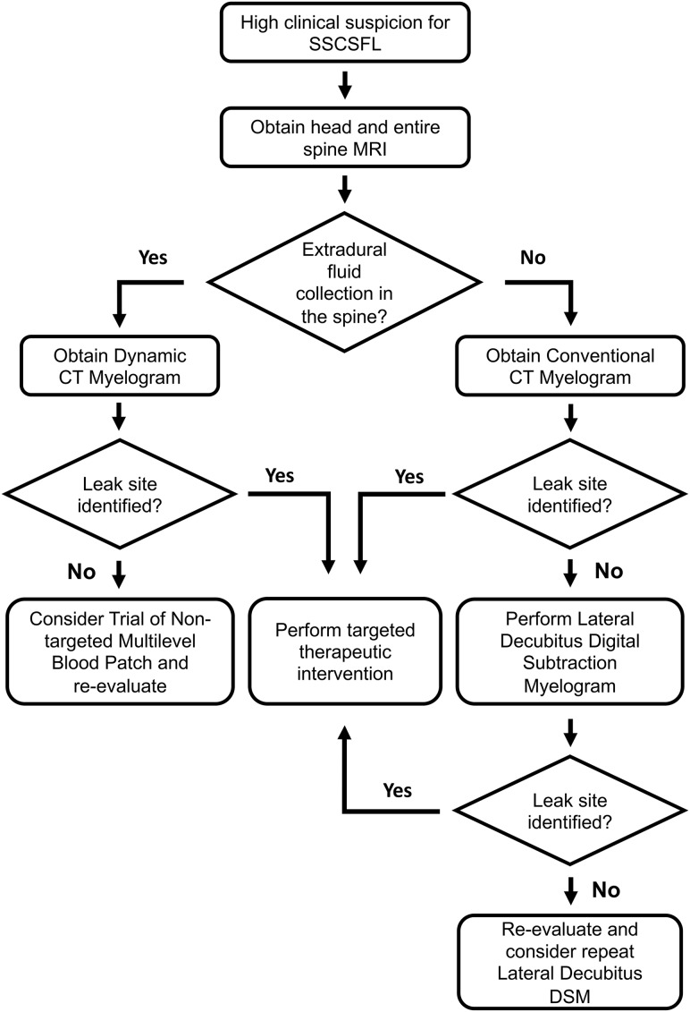
Patients who present with new persistent daily headache with orthostatic features, worse with upright posture and partial or incomplete relief with recumbency and/or exacerbation with Valsalva, have high clinical suspicion for SSCSFL. These patients first undergo brain and entire spine imaging. The spine MR imaging is used to assess extradural fluid collections, and the brain MR imaging is used to look for manifestations of CSF hypotension and to further stratify the pretest probability.4,5 At Mayo Clinic, patients are first evaluated in our CSF dynamics clinic by neurologists who specialize in headache disorders and intracranial hypotension, and if there is no extradural fluid collection in the spine MR imaging, we generally proceed with a conventional CT myelography with early and delayed images. If CT myelography findings are negative, lateral decubitus DSM is performed to look for CSF-venous fistulas or other slower CSF leaks. If the spine MR imaging demonstrates an extradural fluid collection, the leak is considered fast, and we proceed with dynamic CT myelography, given its high detection rate for the location of this type of CSF leak.6 A flow diagram for the SSCSFL diagnostic imaging algorithm is presented in Fig 1. Our initial unpublished data suggested an approximately 50% rate of finding a CSF venous fistula in patients with negative CT myelography findings referred from our CSF dynamics clinic for high clinical suspicion.
Fig 1.
SSCSFL diagnostic imaging algorithm flow diagram.
Equipment and Supplies
DSM requires an x-ray system with a high-resolution flat panel detector and a high-power x-ray tube, similar to the ones used for cerebral and spinal angiography. We use Allura Xper FD 20/20 (Philips Healthcare, Best, the Netherlands) with spinal angiography set to 1 frame per 1–2 seconds. A tiltable table is preferred to adjust spine angling and control the contrast flow speed. Although it is not completely necessary, we have found that it is useful to have a wedge-shaped cushion to position a patient’s hips more superiorly relative to the shoulders. Although our x-ray system is biplane, only a single plane is used for the procedure. We have used the MD Eleva system (Philips Healthcare) but were unable to get diagnostic images due to tube overheating. Although there may be other fluoroscopic units suitable for this examination, we have successfully acquired diagnostic-quality images using Axion Artis dTA ceiling mount (Siemens, Erlangen, Germany) and Allura Xper FD, and in our opinion, images from the Allura Xper FD are sharper and easier to interpret.
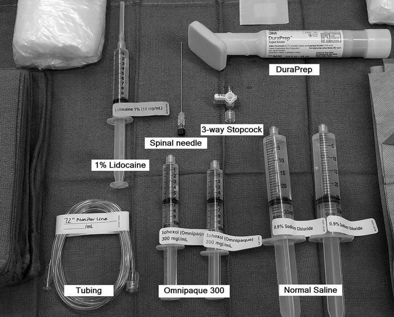
Our current setup for the DSM includes the following supplies (Fig 2) (manufacturer’s information for our current setup is included as a reference, but we recognize that there may be similar products just as suitable for this procedure): a 20-ga spinal needle (BD spinal needle; Becton Dickson, Franklin Lakes, New Jersey), Omnipaque 300 contrast (GE Healthcare, Milwaukee, Wisconsin), sterile preservative-free normal saline, 3-way stopcock (Merit Medical Systems, South Jordan, Utah), 72-inch tubing (NAMIC pressure monitoring line; Navilyst Medical, Marlborough, Massachusetts), two 10-mL syringes, and two 30 mL syringes. The maximum recommended daily intrathecal dose of Omnipaque 300 is 10.2 mL. We have been using a total of 11 mL per day and dividing the contrast into two 10-mL syringes, 6 mL in one and 5 mL in the other. The 6-mL syringe is used for the upper thoracic run followed by 5 mL for the lower thoracic/upper lumbar region. Two 30-mL syringes are also filled with normal saline. The long tubing is 72 inches (183 cm) and holds approximately 3 mL of injectate. Typically, DuraPrep (3M, St. Paul, Minnesota) is used for skin preparation.
Fig 2.
Supplies for DSM.
Procedure Technique
DSM is a 2-day procedure due to dose constraints of intrathecal Omnipaque 300. The patient receives 11 mL of intrathecal Omnipaque on the first day for DSM of one side and typically returns the following day for an additional 11 mL of intrathecal Omnipaque for DSM on the other side. We have performed >100 DSM runs in the past year without any major complications from intrathecal Omnipaque administration. Omnipaque 300 is the preferred concentration because we used Omnipaque 240 during our initial DSM experience and found it too dilute, and the ability to see subtle structures such as CSF-venous fistulas is compromised, even with the digital subtraction technique. Omnipaque 350 and 140 are contraindicated for intrathecal use.
DSM is performed with the patient in the lateral decubitus position on one side, and the patient returns the next day for the same procedure on the other side. For each side, 2 separate DSM runs are performed, typically, the first run with the FOV from the lower cervical-to-mid-/lower thoracic level, and the second run with the FOV mildly overlapping the mid-/lower thoracic level to the lumbar puncture level. A ruler or radiopaque markers are placed on the nondependent aspect of the spine to ensure appropriate vertebral counting between the 2 runs. Although the mid-to-upper cervical spine and lower lumbar spine are not routinely included (CSF-venous fistulas are thought to be rare in these locations), if needed, these levels can be assessed in the subsequent decubitus CT myelogram. DSM can be performed with the patient under general anesthesia or awake with or without moderate sedation, depending on the patient. Many patients develop headache or pressure when the contrast flows intracranially, similar to other myelograms. Given the need to minimize movement, it may be beneficial to give moderate sedation to awake patients to alleviate discomfort.
Patient Positioning.
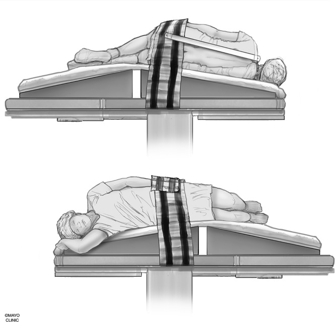
We use a custom-made wedge to position the hips higher than the shoulders to allow preferential cranial flow of contrast from the lumbar region by gravity (Fig 3). Although a custom-made wedge may be sufficient, a tiltable angiography table is preferred for maximum control of the contrast flow speed because the wedge may be too steep or not steep enough, depending on patient’s body habitus. Patients need to be in as perfect a lateral decubitus position as possible to ensure that the neural foramina and nerve sheath diverticula have maximal exposure to the iodinated contrast and to increase the likelihood of optimally imaging potentially very subtle CSF-venous fistulas. Goals of positioning include moving all leads, IVs, tubing, clothing, and anything else physically located on the patient away from the midline so that they will not interfere with image quality during the DSM.
Fig 3.
Patient positioning. A custom-made wedge is used to position the hips higher than the shoulders to create cranial flow of the contrast from the lumbar region by gravity. Reprinted with permission from the Mayo Foundation for Medical Education and Research. All rights reserved.
Positioning of the arms can be problematic, especially if the examination is performed with the patient under general anesthesia. The dependent arm typically can be tucked in close to the body and will be away from midline, as long as lateral positioning is maintained. If the patient begins to lean forward or backward, then the dependent arm may project across the midline. The superior arm can be positioned slightly to the front of the side and may need to be secured to maintain that position. It is not ideal for the superior arm to be positioned immediately along the side of the body. Positioning of lower extremities is not as important as long as the lumbar spine FOV is not obscured. During the placement of the needle into the thecal sac, it is advisable to move the fluoroscopy unit into an anterior-posterior position with respect to the table to image the patient in the lateral view to avoid the needle puncturing the ventral dura. A ventral dural puncture can induce a temporary leak and has the potential to result in a nondiagnostic study. If the superior arm is along the side, it may interfere with clearly seeing the precise location of the needle tip during the needle placement.
Needle Positioning.
Intrathecal access is obtained in a manner similar to a typical myelography.7 However, the combination of lateral decubitus positioning and CSF hypotension can make the needle positioning difficult at times. The needle is advanced slowly as the needle position is checked in anterior-posterior and lateral views, and once the needle position is confirmed to be in the center of the bony spinal canal, a small amount of iodinated contrast is injected while observing under fluoroscopy in the lateral view to confirm intrathecal positioning.
Injectate Preparation.
The long tubing is connected to the 30-mL saline flush through the 3-way stopcock. Normal saline is flushed through the tubing while keeping the third port unflushed, thereby keeping air in the hub of the third port. The 10-mL syringe with 6 mL of Omnipaque is then connected to the third port while maintaining an air bubble within that port. The other end of the long tubing is secured to the hub of the spinal needle, and 10–20 mL of sterile normal saline may be injected slowly to pressurize the thecal sac. Afterward, the 3-way stopcock is switched to open the tubing to the contrast, and the contrast is slowly injected through the tubing while following the air bubble that separates the contrast from the saline. Once the contrast column reaches the hub of the spinal needle, the injection is paused, the patient position is double-checked, possible causes of artifacts are corrected, and the patient (or the anesthesiologists/nurse anesthetists in general anesthesia cases) is coached on the importance of keeping still and breath-holding. The patient is coached about shallow/quiet breathing once he or she is no longer able to breath-hold.
Digital Subtraction Myelography Image Acquisition.
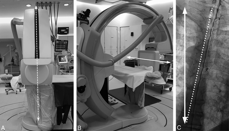
The caudal-to-cranial tilt from the wedge will naturally cause contrast to flow cephalad. Due to differences in body habitus and boosting from pillows or blankets, the tilt angle of the table provided by the angiography unit is not representative of the actual degree of spine tilt with respect to the floor. The true angle of the spine with respect to the floor can be assessed by positioning the image intensifier in a lateral position with respect to the table and the fluoroscopy unit vertical to the floor. A vertical line in the fluoroscopic image obtained this way will correspond to the horizontal axis with respect to the floor (Fig 4). Approximately 5°–7° of spine tilt with respect to this axis is optimal so that the contrast progresses cranially at about 1–2 vertebral segments per second.
Fig 4.
Defining the true horizontal axis and spine tilt on DSM. By placing the C-arm in a vertical position with respect to the floor (A, dotted arrows) while maintaining the long axis of the image intensifier orthogonal to the C-arm (B, solid arrow), the long axis of the image intensifier and the long axis of the image are aligned horizontally, parallel to the floor (B and C, solid arrow). The angle between this line and the line connecting the spinous processes (C, dotted line) defines the spine tilt with respect to the floor.
The image intensifier is first positioned to span the lower cervical spine to mid-/lower thoracic level. The image is optimized by collimating the x-ray beam and using filters as necessary, focusing on the dependent side of the spine where the contrast will layer due to gravity. Because the imaged region is well above the lumbar puncture site, it takes usually 3–5 seconds for the contrast to reach the imaged region. Therefore, the proceduralist should start injecting the contrast first, wait about 2 seconds, then have the patient breath-hold while starting the digital subtraction image acquisition. Once all 6 mL of contrast is injected from the syringe, the 3-way stopcock is rapidly switched to open up the normal saline into the tubing and inject about 5 mL of normal saline to flush the remaining contrast within the tubing and push the contrast lingering in the lumbar region cranially. Once contrast reaches the most superior level visible in the FOV, it is no longer necessary to continue flushing with normal saline. Diagnostic image acquisition should continue until the most superior nerve sheaths have had adequate time to be exposed to the contrast. We have found that image-acquisition length should be at least 45 seconds, though longer may be beneficial. The patient is instructed to resume quiet breathing if unable to breath-hold for the full duration of image acquisition because diagnostic-quality images can still be obtained with quiet breathing.
To prepare for the mid-/lower thoracic-to-lumbar region imaging, sterile normal saline is reloaded in the 30 mL syringe, and the empty 10-mL contrast syringe is disconnected. The 3-way stopcock from the saline port to the now-empty port is opened, the normal saline syringe is drawn back to recreate an air pocket, and then the 10-mL syringe filled with 5 mL of Omnipaque is connected to the air-filled hub of the 3-way stopcock. The table and image intensifier are positioned so that the needle tip is at the lower end of the image. If there is more than trace amount of residual contrast layering within the thecal sac, normal saline can be injected to push the contrast cranially. Afterward, in a similar manner, the contrast column in the tubing is advanced to the hub of the spinal needle by using the position of the bubble.
Because the needle is at the lower edge of the FOV, the contrast column will appear in the image almost immediately as contrast is injected. The patient should breath-hold, the digital subtraction acquisition is started, and then contrast is injected. Once all contrast in the syringe is injected, the stopcock is rapidly switched to open up the normal saline to the tubing and flush the remaining contrast in the tubing. Again, the goal is to image long enough so that each neural foramen is adequately exposed to contrast, at least ≥45 seconds if possible.
The tubing should be disconnected from the needle, the stylet reset, the spinal needle removed, and a sterile dressing placed. If indicated, one may scan up and down the spine under fluoroscopy and take some magnified spot images.
Further Diagnostic Optimization Options
DSM can be performed with the patient under general anesthesia, moderate sedation, or without sedation depending on radiologist’s preference and a variety of patient factors. General anesthesia is helpful to minimize motion artifacts, but there are other factors that can be problematic, such as positioning the patient in the lateral decubitus position under general anesthesia, artifacts from ventilation and monitoring equipment, and limitations of arm placement due to the risk of brachial plexus injury. For larger patients, we rarely perform DSM with the patient under general anesthesia because the body habitus makes it difficult to place and maintain the patient in the lateral decubitus position. Moderate sedation can be effectively used in patients who are cooperative and have the ability to carefully follow breathing instructions. The area of interest is within the first 1–2 cm from the spinal canal overlying the vertebra and transverse processes, which is typically less degraded by respiratory motion. Correlating subtracted images with the unsubtracted images is helpful to clarify potential motion artifacts.
Another option to potentially increase the diagnostic yield is to perform a lateral decubitus CT myelography immediately following DSM, without repositioning the patient. Diagnostic yield for the additional CT study is yet to be determined and needs further evaluation. At this time, we perform lateral decubitus CT myelography on all patients with negative findings on DSM because we have seen a patient in whom a subtle fistula was missed in DSM, which was subsequently detected in a decubitus CT myelogram. We obtain the entire spine CT in a single pass in a dual-energy setting (100 kV and 140 kV) and create 50-keV monoenergetic reconstructions to maximize detection of subtle contrast leakage.8,9
Image Interpretation.
Both the subtracted and unsubtracted DSM images and, if available, subsequent decubitus CT myelograms, are scrutinized for CSF leaks and CSF-venous fistulas (Fig 5 and On-line Video Clip 1). In our experience, the decubitus CT myelogram often helps to problem-solve findings on the DSM and confirm the location of diverticula. To facilitate DSM image processing, we briefly review DSM images at the technologist’s console to look for an obvious leak and to remask the images in case of gross patient motion. Obtained and processed images are then reviewed on the PACS. The 100-kV and 50-keV CT myelograms are reviewed in detail under multiplanar reconstructions.
Fig 5.
Examples of diagnostic DSM. Full-FOV DSM images from a lower cervical-to-mid-/lower thoracic run clearly delineate a CSF-venous fistula in the unsubtracted image (A) and subtracted image (B). A digitally magnified unsubtracted image from another patient shows a very subtle CSF-venous fistula (C), which is better seen in a subsequent CT myelogram (D).
Common Artifacts/Pitfalls.
Due to the daily maximum intrathecal dose of Omnipaque 300, if the study is nondiagnostic, the patient needs to return on a different day for a repeat procedure. This is a major inconvenience, causes unnecessary additional radiation exposure to the patient, and is an inopportune use of medical resources. This section shows examples of common artifacts and pitfalls and ways to prevent or minimize their effects.
Patient Rotation.
The ideal DSM position for detection of CSF-venous fistulas is to have the patient completely in a 90° lateral decubitus position and the x-ray beam horizontal to produce a straight contrast meniscus. If the patient is deviated from the 90° lateral decubitus position and the beam is horizontal, there will be foreshortening of the nerve root sheaths and the contrast within the thecal sac could potentially obscure the CSF-venous fistula (Fig 6). If the patient is tilted from true lateral decubitus position and the detector is also tilted to produce an anterior-posterior image, the contrast column will be slanted, making the contrast appear less dense, and less contrast will layer laterally to opacify the fistula.
Fig 6.
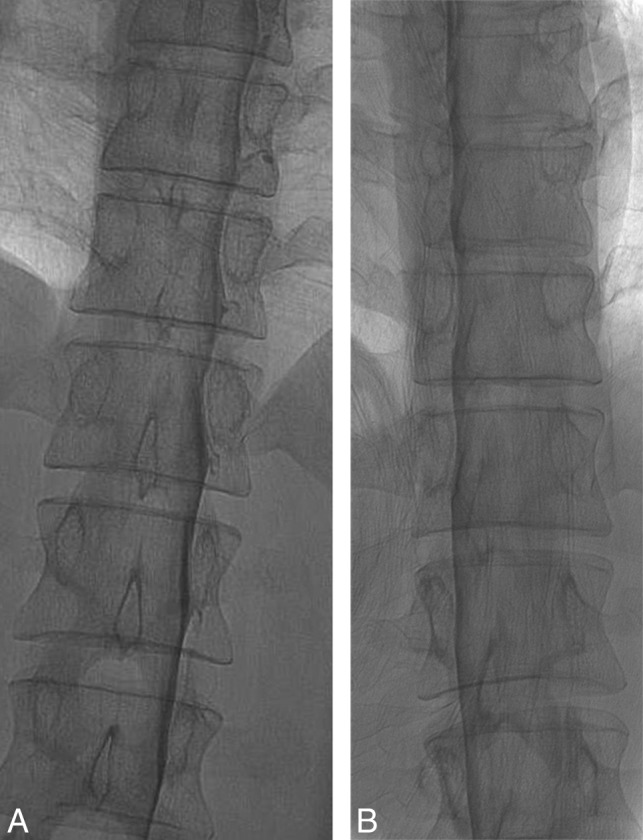
Effect of patient rotation on the image. A, An unsubtracted image from a DSM study obtained with the patient in the true right lateral decubitus position and the image intensifier horizontal shows the contrast outlining the exiting nerve roots and filling small nerve sheath diverticula. B, An unsubtracted image from a DSM study from the same patient in the oblique left lateral decubitus position and the image intensifier horizontal shows partial obscuration of the contrast in the nerve sheaths due to an overlying contrast column within the thecal sac. Note the differences in the position of the spinous processes indicating the patient obliquity.
Suboptimal Contrast-Flow Speed.
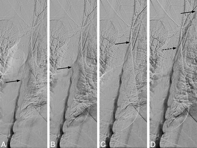
There needs to be an even and sufficient layer of contrast within thecal sac at all imaged levels to optimize opacification of a potential CSF-venous fistula. If the contrast flows too fast, not enough contrast column will be available to fill the fistula, and if contrast flow is too slow, not enough time will be available for the upper levels to fill the fistula before the patient needs to breathe. Straight spine alignment provides an even contrast flow, and spine tilt with respect to the floor determines the overall speed of the contrast. We have found that contrast progression of 1–2 levels per second provides an optimal contrast column (Fig 7).
Fig 7.
Uneven contrast flow. Consecutive DSM images at 1 frame per 2 seconds, with the leading edge of the contrast column denoted by the solid arrows. A and B, Initial optimal flow with 1-level progression per second, but subsequent images in C and D show contrast progressing more rapidly, 2–4 levels per second. Note that only a thin layer of contrast is visible at the convex aspect of the spine curvature and less contrast is available to opacify a potential CSF-venous fistula at this level (D, dotted arrow).
Subdural Injection.
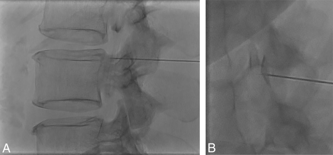
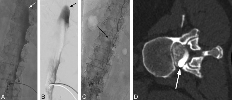
The combination of CSF hypotension, lateral decubitus positioning, and forceful injection into the thecal sac make it relatively easy to perform a subdural injection. CSF hypotension causes tenting of the thecal sac, which makes intrathecal access difficult at times despite positioning the spinal needle tip in the middle of the bony spinal canal. Therefore, it is imperative that a test injection be performed to confirm the intrathecal needle position (Fig 8). Despite confirming intrathecal access and keeping the needle still as the thecal sac is rapidly pressurized, the needle occasionally backs out and causes subdural injection (Fig 9). Although this issue usually results in partial subdural injection with enough intrathecal contrast for adequate diagnostic yield, we use a 20-ga needle instead of a smaller gauge needle to minimize the needle backing out due to the pressure. In addition, it is not necessary to have too strong an injection with the 20-ga needle because the optimal flow rate is a 1- to 2-level progression per second. The first indicator that an injection may be subdural is when contrast takes longer to arrive at the inferior part of the image on the first run. This is then followed by a masslike contrast collection, often in the middle of the spine rather than the expected layering meniscus of contrast filling the nerve sheaths and nerve sheath diverticula. If this occurs, it is still worthwhile to continue if there is some intrathecal contrast flow because the source of the leak may still be found.
Fig 8.
Tenting of the thecal sac and confirming intrathecal contrast flow. A, Lateral view spot image with a test injection shows contrast outlining the nerve roots, confirming intrathecal needle positioning. B, Lateral view spot image with a test injection in a different patient shows tenting of the thecal sac and subdural contrast despite the needle tip appearing to be well within the bony spinal canal.
Fig 9.
Mixed subdural and intrathecal injection. Unsubtracted (A) and subtracted (B) images from the DSM study demonstrate a subdural contrast injection superimposed on some intrathecal contrast. Note the masslike contrast extending cranially (arrows) rather than normal layering meniscus of intrathecal contrast. Unsubtracted image from the DSM study from another patient shows a small amount of masslike subdural contrast column extending cranially (C, arrow), which is confirmed on the subsequent decubitus CT myelogram (D, arrow).
Artifacts from Superimposed Objects.
Various objects overlying the patient can cause artifacts that can degrade the diagnostic quality of the DSM. This is especially problematic in patients under general anesthesia due to various monitoring leads and support material to keep the patient in the lateral decubitus position (On-line Figure). It is important to recognize these potential causes of artifacts before contrast injection and adjust as many overlying objects as possible to optimize image quality.
CONCLUSIONS
DSM is an excellent diagnostic tool for assessment of various types of CSF leaks, and lateral decubitus DSM is increasingly being used to diagnose subtle CSF-venous fistulas. Meticulous technique and attention to detail are critical for procedure optimization and interpretation. Neuroradiologists should be familiar with optimal techniques and common pitfalls and artifacts to improve diagnostic yield and prevent nondiagnostic examinations.
Acknowledgments
The authors acknowledge the assistance of Dr Sonia Watson in editing the manuscript.
ABBREVIATIONS:
- DSM
digital subtraction myelography
- SIH
spontaneous intracranial hypotension
- SSCSFL
spontaneous spinal CSF leak
Footnotes
Disclosures: Jeremy K. Cutsforth-Gregory—UNRELATED: Board Membership: Spinal CSF Leak Foundation Medical Advisory Board, Comments: This is a completely volunteer position, without financial or in-kind compensation; Royalties: textbook royalties from Oxford University Press, Comments: Mayo Clinic Medical Neurosciences. 6th ed.
References
- 1.Schievink WI. Spontaneous spinal cerebrospinal fluid leaks and intracranial hypotension. JAMA 2006;295:2286–96 10.1001/jama.295.19.2286 [DOI] [PubMed] [Google Scholar]
- 2.Hoxworth JM, Trentman TL, Kotsenas AL, et al. . The role of digital subtraction myelography in the diagnosis and localization of spontaneous spinal CSF leaks. AJR Am J Roentgenol 2012;199:649–53 10.2214/AJR.11.8238 [DOI] [PubMed] [Google Scholar]
- 3.Schievink WI, Moser FG, Maya MM, et al. . Digital subtraction myelography for the identification of spontaneous spinal CSF-venous fistulas. J Neurosurg Spine 2016;24:960–64 10.3171/2015.10.SPINE15855 [DOI] [PubMed] [Google Scholar]
- 4.Farb RI, Nicholson PJ, Peng PW, et al. . Spontaneous intracranial hypotension: a systematic imaging approach for CSF leak localization and management based on MRI and digital subtraction myelography. AJNR Am J Neuroradiol 2019;40:745–53 10.3174/ajnr.A6016 [DOI] [PMC free article] [PubMed] [Google Scholar]
- 5.Dobrocky T, Grunder L, Breiding PS, et al. . Assessing spinal cerebrospinal fluid leaks in spontaneous intracranial hypotension with a scoring system based on brain magnetic resonance imaging findings. JAMA Neurol 2019;76:580–87 10.1001/jamaneurol.2018.4921 [DOI] [PMC free article] [PubMed] [Google Scholar]
- 6.Luetmer PH, Schwartz KM, Eckel LJ, et al. . When should I do dynamic CT myelography? Predicting fast spinal CSF leaks in patients with spontaneous intracranial hypotension. AJNR Am J Neuroradiol 2012;33:690–94 10.3174/ajnr.A2849 [DOI] [PMC free article] [PubMed] [Google Scholar]
- 7.Hudgins PA, Fountain AJ, Chapman PR, et al. . Difficult lumbar puncture: pitfalls and tips from the trenches. AJNR Am J Neuroradiol 2017;38:1276–83 10.3174/ajnr.A5128 [DOI] [PMC free article] [PubMed] [Google Scholar]
- 8.Postma AA, Das M, Stadler AA, et al. . Dual-energy CT: what the neuroradiologist should know. Curr Radiol Rep 2015;3:16 10.1007/s40134-015-0097-9 [DOI] [PMC free article] [PubMed] [Google Scholar]
- 9.Shuman WP, Chan KT, Busey JM, et al. . Dual-energy CT aortography with 50% reduced iodine dose versus single-energy CT aortography with standard iodine dose. Acad Radiol 2016;23:611–18 10.1016/j.acra.2015.12.019 [DOI] [PubMed] [Google Scholar]


