Significance
From foldable chairs and umbrellas to tents and solar panels, many structures are capable of quickly changing their shape and therefore, function. The design of these deployable structures poses two main challenges. First, transformation needs to be reliable and autonomous, and second, systems have to be stable and locked in place in the deployed state. Using a combination of experiments and analyses, we demonstrate that bistable linkages and transition waves provide a powerful platform for realizing deployable structures. We first carefully design the bistable joints so that the transition wave propagates through the entire linkage, transforming the initial straight structure into a curved one. Then, we use these elements as building blocks to create deployable three-dimensional structures of arbitrary shape.
Keywords: transition wave, multistability, bistable mechanism, deployable structures
Abstract
Transition waves that sequentially switch bistable elements from one stable configuration to another have received significant interest in recent years not only because of their rich physics but also, for their potential applications, including unidirectional propagation, energy harvesting, and mechanical computation. Here, we exploit the propagation of transition waves in a bistable one-dimensional (1D) linkage as a robust mechanism to realize structures that can be quickly deployed. We first use a combination of experiments and analyses to show that, if the bistable joints are properly designed, transition waves can propagate throughout the entire structure and transform the initial straight configuration into a curved one. We then demonstrate that such bistable linkages can be used as building blocks to realize deployable three-dimensional (3D) structures of arbitrary shape.
Multistability—the property of having multiple stable equilibrium configurations—has recently emerged as a powerful platform to design a wide range of smart structures, including shape-reconfigurable architectures (1–4), fully elastic and reusable energy-trapping metamaterials (5), soft swimming robots with preprogrammed directional propulsion (6), and deployable solar panels for aerospace applications (7). Interestingly, the range of attainable functionalities can be further expanded when considering networks of elastically coupled multistable building blocks since these support the propagation of transition waves that sequentially switch the elements from one stable configuration to the other (8–10). By applying a stimulus large enough to overcome the initial energy barrier, a bistable building block switches from its higher-energy stable configuration to its lower-energy one and releases the energy difference (initially stored in the form of deformation). If such energy is transmitted to the neighboring elements through (elastic) connections, waves similar to those of a falling dominoes (11) are initiated that switch sequentially all building blocks. It has been recently shown that such transition waves offer new opportunities to manipulate the propagation of mechanical signals and enable unidirectional propagation (8, 12, 13) and energy harvesting (14, 15) as well as simple mechanical logic (9); here, we will investigate their use to realize foldable structures that can be quickly deployed and automatically lock in place.
Deployable structures that can be packaged for transportation and expanded at the time of operation not only surround us every day in the form of foldable chairs, tables, and umbrellas but also enable the design of smart aerospace (16–18), architectural (19–22), engineering (5, 23, 24), and medical (25) systems. These structures are routinely realized using linkage mechanisms consisting of rigid bars connected by mechanical joints (19–21, 26–28). However, there are several challenges associated with their design. 1) The deployment process (i.e., the transformation between the compact/packaged and large/deployed states) poses several constraints as it should be autonomous, be reliable, and occur without any damage (29). 2) They require robust mechanisms to lock them into place after deployment (30).
In this work, we study via a combination of experiments and numerical/theoretical analyses the nonlinear dynamic response of a simple mechanical linkage comprising bistable joints connected by rigid bars. We first show that, by carefully designing the connections between the links, the system supports transition waves that propagate through the entire structure, transforming the initial straight configuration to a curved one. Then, we demonstrate that these bistable linkages can be combined to realize arbitrary curved profiles and three-dimensional (3D) shapes out of initially straight and flat elements. As such, the proposed platform provides opportunities for the design of a generation of deployable systems that can be expanded quickly by applying a single perturbation and that are stable and locked into place after deployment (since the retraction process requires far more energy than the deployment one).
Dynamics of a Linkage with Nearest Neighbors Connections
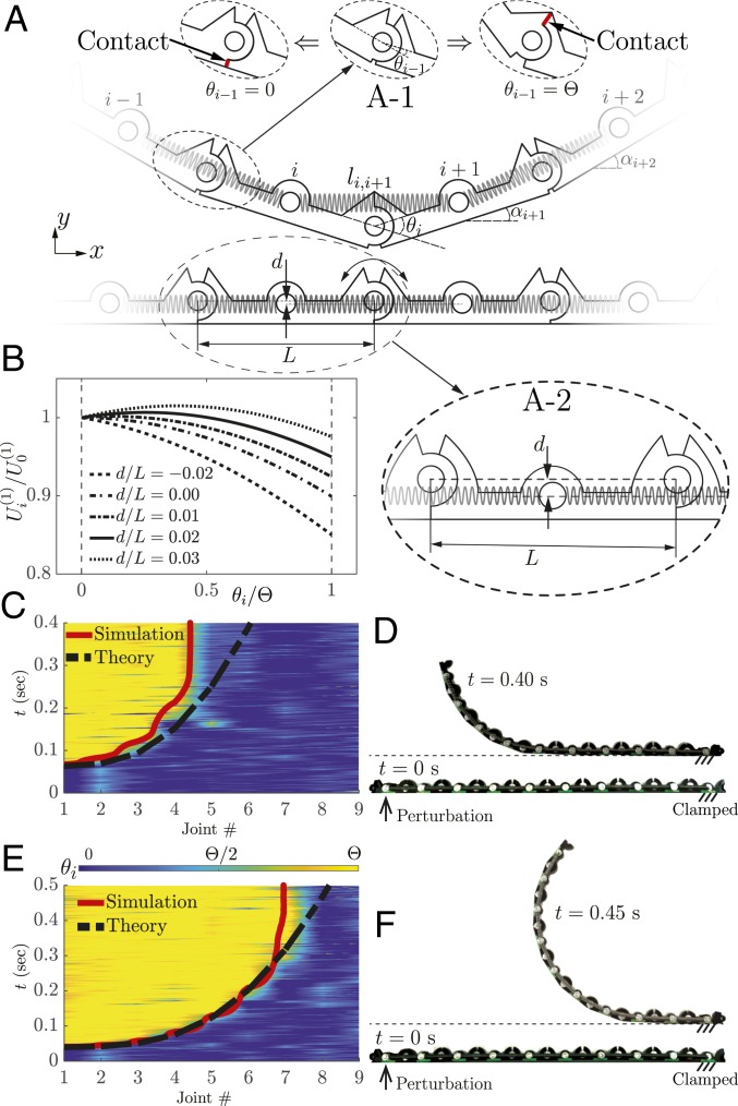
We consider a simple mechanical linkage comprising a one-dimensional (1D) array of rigid bars of length , mass , and moment of inertia connected at their ends by joints designed to allow rotations in the interval (Fig. 1A). To make the structure multistable, we connect nearest neighbors together with linear springs with stiffness , rest length , and ends fixed in the middle of the links at a distance from the line connecting the center of the joints together. For such system, the potential energy stored in the springs depends only on the angle between two adjacent bars so that the joints are independent from each other. More specifically, the potential energy of the spring connecting the th and th rigid bars, , takes the form
| [1] |
where for nearest neighbor connections, = 1 and is the length of the spring connecting the th and th bars. In Fig. 1B, we report the evolution of [normalized by the energy of the spring when the two connected bars are aligned, ] as a function of the joint angle ( being the angle between the th bar and the horizontal direction) for different values of . The results indicate that, while for , the hinges are unstable at the initial resting flat state (i.e., at ), increasing the distance makes both the joints stable at and decreases the total amount of energy released when the joint moves from to . More specifically, for , , and any small perturbation results in switching of the joint angle from to . Differently, when , , and the joint angle returns back to after small perturbations.
Fig. 1.
Bistable linkage with nearest neighbor connections. (A) Schematic of the system. Insets show (A-1) the design of the joints to allow rotation in the range (note that the edges in contact are highlighted in red) and (A-2) the distance . (B) Evolution of the potential energy of a joint as a function of its angle for various values of . (C and E) The normalized angle of the individual bistable joints ( for each of the joints in the linkage) during the propagation of the transition wave in a linkage with as recorded in two experiments in which the impactor prescribes a perturbation to the first bar characterized by = (C) 0.50 and (E) 2.76. The corresponding numerical and theoretical predictions for the wave front are shown with solid red and dashed black lines, respectively. (D and F) Corresponding experimental snapshot of the structure in the initial (straight) and final (curved) configurations.
Guided by these results, we choose and build a chain comprising bars with mm, g, and g ; joints characterized by ; and springs with N/mm and mm (SI Appendix, section 2). We place the structure in the straight configuration on a flat surface in the plane (note that gravity acts in the direction), clamp its right end, and apply a pulse in the direction to leftmost link with a fast moving rod. We then monitor the propagation of the excited transition waves with a high-speed camera (SONY RX100) recording at 480 fps. Finally, we obtain the position, , and orientation, , of the th link in each frame via image processing methods and use those to further calculate velocity , angular speed , and kinetic energy (SI Appendix, section 1):
| [2] |
In Fig. 1 C and E, we show results for two experiments (Movies S1 and S2) in which the impactor prescribes a perturbation to the first bar characterized by 0.50 and 2.76, respectively. Since the applied perturbations provide enough energy to overcome the initial energy barrier in the joint’s potential [ for ] (Fig. 1B), they make the first joint to snap so that suddenly moves from 0 to . Additionally, they initiate a transition wave that sequentially switches the joints from to , transforming the initial straight structure into a curved one. However, the velocity of such transition wave monotonically decreases as it propagates rightward and eventually vanishes. As a matter of fact, for the input signal characterized by , the last five links remain in their flat configuration (Fig. 1D). By increasing the magnitude of the applied perturbation to , the distance traveled by the wave is enlarged to seven units, but such high-energy inputs cause larger stresses and therefore, make the structure more susceptible to failure (which manifests itself in the form of cracks around the connecting pins as those are the weakest points of the structure).
To understand the reason behind the arrest of the excited transition waves, we continue by developing a numerical model. We assume that the chain stays in the plane and define the Lagrangian of the chain
| [3] |
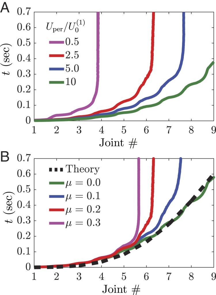
where for nearest neighbor connections and is the energy associated with the constraints introduced at the joints to ensure that subsequent links stay connected and that (SI Appendix, section 1). The discrete equations of motion are then obtained via the Euler–Lagrange equations, and Coulomb friction terms of type ( being the experimentally measured coefficient of friction between the structure and the surface) are introduced to account for the energy dissipation due to the sliding of the structure on the surface. Finally, the ordinary differential equations are numerically solved using the Runge–Kutta fourth-order method. In our numerical analysis, we consider a linkage comprising 10 bars, apply the experimentally extracted input signal to the first link on the left, and implement fixed boundary conditions at the right end. To test the relevance of the numerical analyses, we first compare the transition wave front predicted by the numerical simulations with that measured in our experiments. As shown in Fig. 1 D and E, we find very good agreement between the two sets of data, confirming the validity of our numerical analyses. Next, we use the simulations to investigate the effect of both friction and strength of the applied input on the propagation of the transition waves. The results shown in Fig. 2 indicate that both larger and smaller help the transition wave to propagate further and that in the limit cases of very high-energy inputs and very small friction all joints snap and the structure reaches its final semicircular shape. However, it is important to note that such final configuration is impractical to reach as it requires either no friction or a high-energy input energy that causes large stresses at the joints.
Fig. 2.
Effect of input energy and dissipation on the wave front. (A and B) Numerically predicted time at which each joint along the linkage with nearest neighbor connections and snaps for (A) different energy inputs and (B) different friction coefficients . Both an increase in input energy and a decrease in friction make the wave propagate further into the structure.
Dynamics of a Linkage with Next-Nearest Neighbors Connections
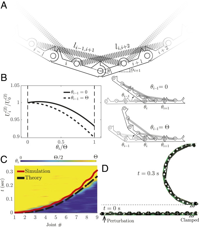
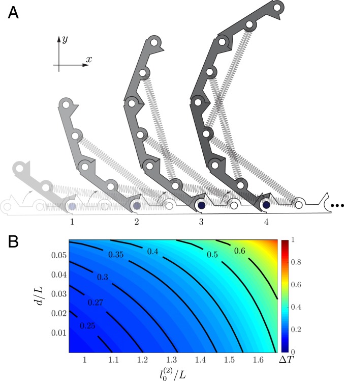
To realize bistable linkages in which transition waves initiated by low-energy inputs propagate through the entire structure even in the presence of moderate levels of dissipation, we change the arrangement of the springs and use them to connect next-nearest neighbor links (Fig. 3A). Note that this change has a significant impact on the energy landscape of the th joint (which is described by Eq. 1 with ) and makes it dependent not only on but also, on and . Specifically, if we consider a wave propagating from left to right, the th joint is stable at both and for , whereas if , changes to a monostable function (Fig. 3B). Remarkably, this qualitative change in potential function allows the transition wave to propagate much more easily through the structure since the snapping of a joint makes the neighboring one monostable and therefore, forces it to snap.
Fig. 3.
Bistable linkage with next-nearest neighbor connections. (A) Schematic of the system. (B) Evolution of the potential energy of a joint as a function of its angle for (solid line) and (dashed line). In both cases, and . (C) The normalized angle of the individual bistable joints ( for each of the joints in the linkage) during the propagation of the transition wave in a linkage with as recorded in an experiment in which the impactor prescribes a perturbation to the first bar characterized by . The corresponding numerical and theoretical predictions for the wave front are shown with solid red and dashed black lines, respectively. (D) Corresponding experimental snapshot of the structure in the initial (straight) and final (curved) configurations.
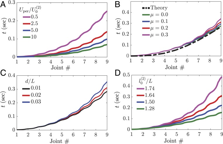
Guided by this analysis, we then modify our structure and introduce linear springs with stiffness N/mm and rest length mm. Note that, since the initial force in the springs is almost identical to that introduced in the linkage with nearest neighbors connections [i.e., ], the stresses at the joints are the same for the two structures and therefore, also their susceptibility to failure. Both our experiments and numerical simulations show that even a small input perturbation characterized by is enough to initiate a wave that switches all joints of the linkage and transform the initially flat structure into a semicircle (Fig. 3 C and D and Movie S3). Furthermore, our numerical analyses indicate that higher-energy inputs result in higher propagation speeds and therefore, faster transitions from the flat to the final curved shape (Fig. 4A). We also find that the propagation of the transition waves is almost unaffected by changes in friction (Fig. 4B) as the amount of energy released by the springs is far greater than that dissipated through friction. Finally, we use our numerical analyses to investigate the effect of the two principal geometric parameters: and . As expected, we find that larger values of result in faster wave propagation (Fig. 4C) since they lead to higher levels of elastic energy stored in the springs. Differently, an increase in leads to slower waves (Fig. 4D) since it is accompanied by a decrease of the amount of energy released by the springs on snapping.
Fig. 4.
Effect of input energy, dissipation, and geometric parameters on the wave front. Numerically predicted time at which each joint along the linkage with next-nearest neighbor connections snaps for different (A) , (B) , (C) , and (D) . In all analyses, unless stated otherwise.
Physical Ingredients
The results of Figs. 3 and 4 indicate that the propagation of transitions waves enables an initially flat linkage with next-nearest neighbor connections to quickly and robustly transform into a curved configuration. Moreover, they also show that, by carefully selecting the geometric parameters and the applied input, the velocity of such waves and therefore, of the deployment process can be controlled. While so far, we have used a combination of experiments and numerical analyses to investigate the propagation of pulses, it is important to point out that the dynamic behavior can be also accurately captured by imposing two basic physical principles: conservation of energy and angular momentum. To demonstrate this important point, we start focusing on the first links rotating around the th joint on the plane (while gravity acts in the direction) (Fig. 5A). Conservation of energy applied to this portion of the structure yields
| [4] |
where is the moment of inertia of the first links with respect to th joint, is the amount of energy released by the springs as the th joint snaps, and and are the angular velocities of the rotating links when and , respectively. Given , Eq. 4 allows us to calculate the angular velocity of the first links when the angle at the th joint reaches its final value . At this point, the first links start to rotate around the th joint, and by imposing conservation of momentum, we obtain
| [5] |
Remarkably, Eqs. 4 and 5 can be used to calculate the time that it takes for the wave to change the th joint angle from zero to , , and therefore, to characterize the transition wave front. More specifically, since is determined from the initial conditions as , they can be recursively used to obtain (with ) and (with ) from which is calculated as
| [6] |
In Figs. 1 C and E, 2B, 3C, and 4B, we compare the transition front predicted by Eq. 6 (dashed black lines) with our experimental and numerical data. In the case of the linkage with next-nearest neighbor connections, we find that the transition front is well captured by the model. Differently, for the structure with nearest neighbor connections, it overpredicts the distance traveled by the wave as friction is not accounted for in our model.
Fig. 5.
Theoretical model. (A) Schematic of a bistable linkage with next-nearest neighbor connections as the transition wave passes through. (B) Theoretically predicted evolution of the time that it takes for the transition wave to reach the last joint, , as a function of the geometrical parameters and .
Having confirmed the validity of our model, we then use it to investigate the effect of the geometric parameters and on the time that it takes for the transition wave to fully propagate throughout the entire structure with next-nearest neighbors connections, . The contour plot reported in Fig. 5B shows that, by tuning the geometric parameters, we can control the propagation velocity of the pulses. More specifically, we find that the rest length of the springs play an important role and that faster pulses propagate for small values of . Note that, since the input energy required to initiate the pulse is much smaller than the energy released , for these calculations we choose (i.e., we ignore the input energy) so that the results represent an upper bound for .
Extension to Arbitrary 3D Shapes
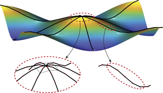
Thus far, we have demonstrated that transitions waves can be exploited to quickly and robustly transform a straight linkage with next-nearest neighbor connections into a semicircle. By spatially varying the angle by which the joints rotate, we can expand the range of achievable shapes on pulse propagation, but we are limited to curves without inflection points (i.e., curves that are either concave or convex). Unfortunately, this is not enough to realize deployable structures capable of transforming into complex surfaces as those required by real-world applications. Realization of such systems necessitates 1) 1D linkages that transform into profiles with arbitrary curvature and 2) connections between them (Fig. 6).
Fig. 6.
Arbitrary surfaces can be realized by connecting our bistable linkages with next-nearest connections.
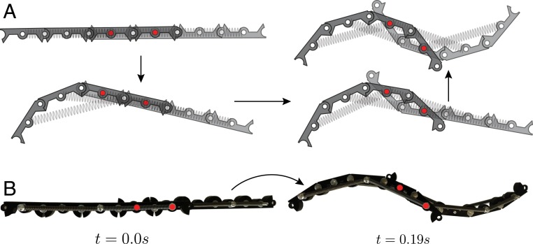
Motivated by practical applications, we focus on the design of a 1D chain capable of transforming into an arbitrary profile and investigate how to realize points at which the sign of the curvature (i.e., the concavity) changes. We find that such inflection point can be easily created by coupling two linkages of the type described in Dynamics of a Linkage with Next-Nearest Neighbors Connections. More specifically, we orient the linkages so that one deforms upward and the other deforms downward and overlay them to get two of their bars to overlap (Fig. 7A). By connecting the extremities of the overlapping links via pins (red circles in Fig. 7A), we form a bistable mechanism that ensures transmission of the wave from one linkage to the other, enabling the transformation of the initially flat linkage into a profile with changing concavity (Fig. 7B and Movie S4).
Fig. 7.
Inflection point. (A) A profile with an inflection point can be obtained by connecting two linkages with next-nearest connections. The joints at which the two linkages are connected together are shown with red circles. (B) Experimental snapshot of a structure in the initial and final configurations. Each linkage consists of four bars with and .
Having identified a strategy to transform a 1D linkage into a profile of arbitrary shape, we lastly focus on how to connect such 1D elements to form networks that span arbitrary open surfaces (Fig. 6). Toward this end, we start by noting that such connections should preserve the integrity of the structure as well as enable transmission of the signal through the different components. If we simply connect several linkages to a rigid element, the links become independent, and the pulses propagate only through the links at which they are excited, not enabling the deployment of the 3D structure. To overcome this limitation, we introduce linear springs that connect the different linkages together (Inset in Fig. 8). As shown in Fig. 8 for a structure comprising four linkages characterized by and , the springs enable the transfer of the waves from one linkage to the other and ultimately, the deployment of the 3D dome-like structure (Movie S5). Note that, contrary to the case of the 1D linkages considered earlier, this 3D structure has to overcome gravity as it lifts from the ground and changes its shape. However, for this system, the energy required to overcome gravity is only 5% of the total energy stored in the springs and therefore, does not affect the deployment process.
Fig. 8.
The 3D deployable structures. A four-linkage structure transforms into a 3D dome-like shape. The four linkages are attached to a central rigid element (highlighted in red in Inset) and interconnected with linear springs.
Conclusions
In summary, we have shown that transition waves provide opportunities to realize structures that can be quickly and efficiently deployed as well as locked in place in the expanded configuration. More specifically, we have focused on a simple 1D linkage and demonstrated that, by introducing next-nearest neighbor connections, the wave can easily and reliably propagate through the system. In contrast to previous studies in which the transition waves have constant velocity when propagating in a system with spatially constant properties (8–10), in our linkages conservation of momentum results in pulses speed that continuously decreases during propagation, similar to those recently observed during curling of an elastica (31). Such velocity profile can be further manipulated by varying the stiffness of the connecting springs along the structure (SI Appendix, Fig. S2). Finally and most importantly, the transition waves in our system transform a straight segment into a curve, and such shape change can be exploited to design deployable structures. Although in this study, we have demonstrated the concept at the centimeter scale, it is important to point out that our approach can be extended to design deployable structures and devices over a wide range of length scales as long as the energy stored in the linear springs is enough to overcome both the dissipated energy and the effect of gravity. Particularly, if we denote with the elastic energy stored by the springs (with , , and denoting the stiffness, length change, and number of the springs, respectively) with the energy dissipated because of friction both at the joint and on the surface and with the energy required to overcome gravity during deployment, the proposed linkages can be transformed into complex surfaces provided that .
Data Availability.
All data discussed in the paper will be made available to readers on request.
Supplementary Material
Acknowledgments
K.B. acknowledges support from NSF Grant DMR-1420570 and Army Research Office Grant W911NF-17-1-0147.
Footnotes
The authors declare no competing interest.
This article is a PNAS Direct Submission. S.A. is a guest editor invited by the Editorial Board.
See online for related content such as Commentaries.
This article contains supporting information online at https://www.pnas.org/lookup/suppl/doi:10.1073/pnas.1917887117/-/DCSupplemental.
References
- 1.Haghpanah B., Salari-Sharif L., Pourrajab P., Hopkins J., Valdevit L., Architected materials: Multistable shape-reconfigurable architected materials (adv. mater. 36/2016). Adv. Mater. 28, 8065–8065 (2016). [DOI] [PubMed] [Google Scholar]
- 2.Kidambi N., Harne R. L., Wang K.-W., Modular and programmable material systems drawing from the architecture of skeletal muscle. Phys. Rev. E 98, 043001 (2018). [Google Scholar]
- 3.Rafsanjani A., Pasini D., Bistable auxetic mechanical metamaterials inspired by ancient geometric motifs. Extreme Mech. Lett. 9, 291–296 (2016). [Google Scholar]
- 4.Shang X., Liu L., Rafsanjani A., Pasini D., Durable bistable auxetics made of rigid solids. J. Mater. Res. 33, 300–308 (2018). [Google Scholar]
- 5.Shan S., et al. , Multistable architected materials for trapping elastic strain energy. Adv. Mater. 27, 4296–4301 (2015). [DOI] [PubMed] [Google Scholar]
- 6.Chen T., Bilal O. R., Shea K., Daraio C., Harnessing bistability for directional propulsion of soft, untethered robots. Proc. Natl. Acad. Sci. U.S.A. 115, 5698–5702 (2018). [DOI] [PMC free article] [PubMed] [Google Scholar]
- 7.Zirbel S. A., et al. , Accommodating thickness in origami-based deployable arrays. J. Mech. Des. 135, 111005 (2013). [Google Scholar]
- 8.Nadkarni N., Arrieta A. F., Chong C., Kochmann D. M., Daraio C., Unidirectional transition waves in bistable lattices. Phys. Rev. Lett. 116, 244501 (2016). [DOI] [PubMed] [Google Scholar]
- 9.Raney J. R., et al. , Stable propagation of mechanical signals in soft media using stored elastic energy. Proc. Natl. Acad. Sci. U.S.A. 113, 9722–9727 (2016). [DOI] [PMC free article] [PubMed] [Google Scholar]
- 10.Deng B., Wang P., Tournat V., Bertoldi K., Nonlinear transition waves in free-standing bistable chains. J. Mech. Phys. Solids, 103661 (2019). [Google Scholar]
- 11.James Stronge W., Impact Mechanics (Cambridge University Press, 2018). [Google Scholar]
- 12.Zheng Y., Wu Z., Zhang X., Wang K. W., A piezo-metastructure with bistable circuit shunts for adaptive nonreciprocal wave transmission. Smart Mater. Struct. 28, 045005 (2019). [Google Scholar]
- 13.Fang H., Wang K. W., Li S., Asymmetric energy barrier and mechanical diode effect from folding multi-stable stacked-origami. Extreme Mech. Lett. 17, 7–15 (2017). [Google Scholar]
- 14.Dorin P., Kim J., Wang K.-W., “Vibration energy harvesting system with coupled bistable modules” in Active and Passive Smart Structures and Integrated Systems XII (International Society for Optics and Photonics, Denver, CO, 2019), vol. 10967, p. 109670G. [Google Scholar]
- 15.Kidambi N., Harne R. L., Wang K. W., Energy capture and storage in asymmetrically multistable modular structures inspired by skeletal muscle. Smart Mater. Struct. 26, 085011 (2017). [Google Scholar]
- 16.Gross D., Messner D., “The able deployable articulated mast–enabling technology for the shuttle radar topography mission” in Proceedings of the 33rd Aerospace Mechanisms Symposium, Boesiger E. A., Litty E. C., Sevilla D. R., Eds. (National Aeronautics and Space Administration, Pasadena, CA, 1999). [Google Scholar]
- 17.Meguro A., Shintate K., Usui M., Tsujihata A., In-orbit deployment characteristics of large deployable antenna reflector onboard engineering test satellite VIII. Acta Astronaut. 65, 1306–1316 (2009). [Google Scholar]
- 18.Wang W., Rodrigue H., Ahn S.-H., Deployable soft composite structures. Sci. Rep. 6, 20869 (2016). [DOI] [PMC free article] [PubMed] [Google Scholar]
- 19.Ziegler T. R., “Collapsible self-supporting structure.” US Patent US4026313A (1977).
- 20.Hoberman C., “Radial expansion/retraction truss structures.” US Patent US5024031A (1991).
- 21.Kassabian P. E., You Z., Pellegrino S., Retractable roof structures. Proc. Inst. Civ. Eng. Struct. Build. 134, 45–56 (1999). [Google Scholar]
- 22.Gantes C. J., Connor J. J., Logcher R. D., Rosenfield Y., Structural analysis and design of deployable structures. Comput. Struct. 32, 661–669 (1989). [Google Scholar]
- 23.Felton S., Tolley M., Demaine E., Rus D., Wood R., A method for building self-folding machines. Science 345, 644–646 (2014). [DOI] [PubMed] [Google Scholar]
- 24.Babaee S., Overvelde J. T. B., Chen E. R., Tournat V., Bertoldi K., Reconfigurable origami-inspired acoustic waveguides. Sci. Adv. 2, e1601019 (2016). [DOI] [PMC free article] [PubMed] [Google Scholar]
- 25.Stoeckel D., Bonsignore C., Duda S., A survey of stent designs. Minim. Invasive Ther. Allied Technol. 11, 137–147 (2002). [DOI] [PubMed] [Google Scholar]
- 26.Britt A. L., Lalvani H., “Symmetry as a basis for morphological analysis and generation of nasa-type cubic deployables” in Proceedings of the IUTAM-IASS Symposium on Deployable Structures: Theory and Applications, Pellegrino S., Guest S. D., Eds. (Springer, Dordrecht, The Netherlands, 1998), pp. 45–54. [Google Scholar]
- 27.Vadstrup Jensen F., Pellegrino S., Expandable ‘blob’ structures. J. Internat. Assoc. Shell Spat. Struct. 46, 151 (2005). [Google Scholar]
- 28.You Z., Chen Y., On mobile assemblies of bennett linkages. Proc. Roy. Soc. A 464, 1275–1293 (2008). [Google Scholar]
- 29.Pellegrino S., Deployable Structures (Springer, 2014), vol. 412. [Google Scholar]
- 30.Rivas Adrover E., Deployable Structures (Laurence King Publishing, London, UK, 2015). [Google Scholar]
- 31.Callan-Jones A. C., Brun P.-T., Audoly B., Self-similar curling of a naturally curved elastica. Phys. Rev. Lett. 108, 174302 (2012). [DOI] [PubMed] [Google Scholar]
Associated Data
This section collects any data citations, data availability statements, or supplementary materials included in this article.
Supplementary Materials
Data Availability Statement
All data discussed in the paper will be made available to readers on request.


