Abstract
Although the power conversion efficiency of perovskite solar cells (PSCs) reached up to 25% that made them comparable to the commercial solar cells, they are facing issues toward commercialization, especially their short lifetime. Remarkably, the most important key factors that regulate the durability of the devices are moisture, light, and heat. In this work, prolonging the device lifetime is focused by designing a flexible moisture-blocked and temperature-controlled encapsulation system. In this regard, a thermally adjusted phase change material is embedded in a polymer encapsulation layer to avoid the moisture diffusion, rapid temperature fluctuation, and undesired crystalline phase change of the perovskite layer in the PSCs under the operation condition. As a result, a 2 year stable device is achieved, whereas the reference device loses more than 50% of its performance after 10 days. Surprisingly, the charge transport resistance and recombination rate show no significant change during 450 days of storage, which confirms no increase in the defect density.
Introduction
Organic–inorganic hybrid perovskite solar cells (PSCs) have attracted a wide attention of researchers because of the exceptional light-absorbing, facile, and affordable processing methods and superior electrical properties such as high charge carrier motilities and long diffusion length. Interestingly, PSCs represent a promising growth in the performance merely in a few years of intensive research.1 In 2009, the power conversion efficiency (PCE) of 3.81% was first achieved in PSCs.2 Ten years later, a PCE as high as ∼25.2% was obtained through continuous attempts in controlling the formation of the perovskite layer and optimization of the device structures.3 Though the PCE of the PSCs has reached the PCEs of the traditional solar cells such as silicon based devices, their short lifetime or low stability has still remained as the main issue and the essential requirement for the commercialization.4
Despite the fact that there is no specific stability protocol for PSCs yet, several key elements were identified as the degradation reasons.5,6 The degradation mechanisms are significantly related to oxygen and moisture diffusion (environmental stability),7,8 temperature and intrinsic heating under the operation condition (thermal stability),9,10 and light (photostability).11,12 Different strategies have been made to improve the stability of PSCs such as the modification of the perovskite material composition or deposition process, replacement of the mesoporous layer, use of different additives and/or charge-transport materials,13 surface treatments and/or interfacial layer engineering,14 use of carbon-based electrodes, and some behavior toward the elimination of the moisture effects.15 As stated, moisture is one of the main vital degradation reasons that causes a complex effect on the perovskite film formation and degradation, especially at higher temperatures.16−18 Besides, a proper humidity level is indispensable for achieving high-quality films and subsequently enhancing the optoelectronic properties.19,20 However, Noh and co-workers suggested that moisture degrades the PCE of unencapsulated PSCs and causes device failure and meanwhile recommended that PSCs should be fabricated in a controlled atmosphere.21
Temperature is another authoritative degradation reason that has a tremendous effect on the components of the PSCs. In addition to the enhancement of the degradation reaction rate because of temperature rise, crystal phase transition of the perovskite materials would occur through the device operation.22 In fact, the presence of phase transitions is consistent with the perovskite nature of the materials.23 There are two phase transitions classified as the high-temperature α-phase and the intermediate temperature β-phase. CH3NH3PbI3 (MAPbI3), the widely used perovskite material in optoelectronic devices, adopts β-phase at room temperature that converts to the α-phase in temperatures higher than 50 °C.22 Thus, the reversible phase transition of CH3NH3PbI3 from a tetragonal to a cubic phase that can occur through the operation of the device cells strongly affects the thermal stability and photostability of PSCs.22 Therefore, the lack of stability issue can be overcome by protecting the device against the moisture diffusion and temperature rise during the operation. The encapsulation of the device by polymer resins is a widely utilized strategy to prevent the diffusion of water and oxygen molecules into the devices and extend their lifetime. So far, various encapsulation systems were employed to delay the degradation that occurred because of the moisture diffusion, although thermal effects were not concentrated in these systems.24 Transparent epoxy resins have been used for some electronic applications because of their low cost, high processing facility, and moderate toughness and because they can be easily cured with heat or ultraviolet (UV) irradiation25,26 by the addition of thermal initiators or photoinitiators, respectively. Han et al.27 applied a transitional glass lid encapsulation onto the PSC. The encapsulated PSC retained 40% of its original efficiency after 20 h at 55 °C in an 80% relative humidity (RH) and under 1 sun illumination. Dong et al. also investigated a similar approach, in which the PSC was encapsulated with a 50 nm thick SiO2 layer deposited by an electron beam, followed by sealing with a cover glass using epoxy glue.28 The encapsulated device retained 70% of its original efficiency after 432 h in an outdoor environment. Matteocci et al. performed a systematic comparative study of sealing methods using epoxy glue. UV-curable glue with a Kapton polyimide adhesive was adapted for the encapsulation of PSCs, which resulted in stable PSCs for 170 h under a 30% RH.29 According to the stability test of the encapsulated CH3NH3PbI3 devices stored in a glovebox and measured under ambient conditions (20–25 °C; RH of 25–40%) for 2500 h, the devices reserved more than 85% of the original PCE.30 In another study, after 2 months of storage under the ambient atmosphere, the encapsulated CH3NH3PbI3–xClx device retained 90% of its initial PCE.31 Likewise, the encapsulated MAPb1–xCaxI3-based device with x = 5% showed a stabilized PCE of 13.3% for over 2 months. The PCE retained 85% of the initial value for a period of over 2 months in the dark and under a RH of 60–70% at room temperature.32 Research progress indicates that developing an effective encapsulation method suitable for PSCs has still remained elusive.
A successful encapsulation system should act as both a moisture barrier and a heat absorber simultaneously, while the aforementioned employed systems comprising polymer resins are naturally thermal insulators that work as barriers for the transfer of the long thermal wavelengths. However, they protect the device against moisture and other corrosive gas molecules, and the device temperature is higher compared to that of the unencapsulated device. It is also desirable for the encapsulation system to be mechanically flexible and optically transparent. So far, encapsulation of PSCs regarding the temperature controlling and heat-transfer management has not been performed. It should be noted that the undesired effect of the encapsulation systems based on polymer materials on the temperature regulation of the devices has not been considered. It is obvious that the decrease of the temperature of a photovoltaic (PV) module can boost the device performance. Generally, some techniques, such as air cooling and water cooling, are utilized to cool the commercial PV module to maintain a lower operating temperature.33 Many numerical and experimental studies have been conducted to find out the most efficient and low-cost hybrid PV/T system. Recently, a phase change material (PCM)-based method for PV thermal regulation has attracted much attention from researchers. In this regard, because the elevated operating temperatures reduce the solar to an electrical conversion efficiency of silicon PV devices, a PV module was directly connected to a PCM-filled glass tank. The PV–PCM system is a hybrid technology in integrating PV panels and PCMs into single modules to achieve higher solar energy conversion efficiency.34 Until now, the PV–PCM system has been used just for silicon-based solar cell modules that are being employed commercially. PCMs can absorb/discharge a large amount of energy over a limited temperature range during phase change. Further, PCMs are of interest for use in applications such as thermal energy storage and thermal management of systems, as well as for active and passive cooling of electronic devices. In fact, the PCM will act as a latent and sensible heat storage medium. It should be noted that using the aforementioned PV–PCM system for cooling the perovskite devices is not possible because of the lack of compatibility with the device structures and lack of the flexibility. Further, the explained system is not able to prevent the diffusion of moisture and oxygen molecules into the devices and just acts as a temperature controller.
In this work, we protect PSCs against both temperature rise and water and oxygen molecules by designing a new shielding system. In fact, the challenge of the linking of PCMs and perovskite devices which are completely different from silicon solar cells is overcome by combining PCM as a cooling agent with a polymer resin that acts as a PCM holder and a moisture and oxygen blocking layer. The designed new encapsulation system is utilized to control the device temperature under the operation condition, prevent the moisture and oxygen diffusion into the device, and subsequently prolong the lifetime of the devices. Remarkably, the perovskite devices encapsulated using the designed protecting system show no loss in their performance after 450 days of storage. Both the PV system and encapsulation system comprising moisture and oxygen barriers and heat absorber materials are characterized using optical, electrical, and thermal analyses.
Results and Discussion
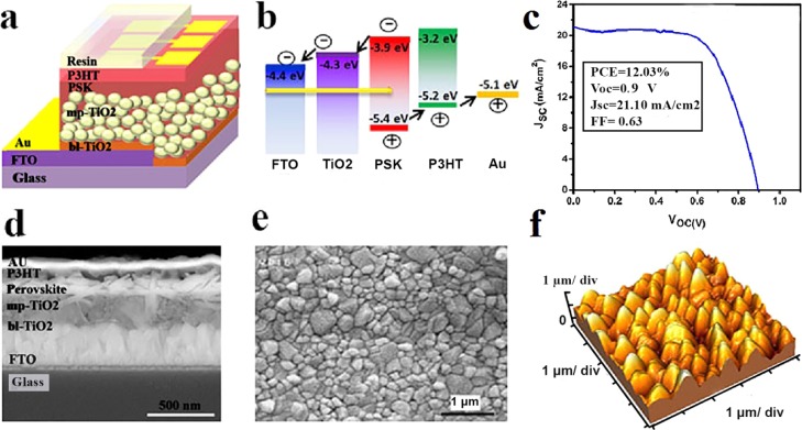
Figure 1a,b shows the schematic illustration of the PSC with a fluorine-doped tin oxide (FTO)/bl-TiO2/mp-TiO2/CH3NH3PbI3/P3HT/Au structure and the energy levels of its components, respectively. As presented in the scanning electron microscopy (SEM) cross-sectional image (Figure 1d), TiO2 and P3HT are employed as the electron-transporting layer (ETL) and hole-transporting layer (HTL) that sandwich the CH3NH3PbI3 layer as the photoactive absorber layer. Figure 1e,f shows the morphology and topography images of the perovskite layer deposited via a two-step method, respectively. The root mean square of the surface of the PSK layer is estimated to be around 50 nm. As the P3HT layer is of low thickness (50 nm) compared to the high roughness PSK layer, the topography of the perovskite layer is dominant. The J–V characteristic of one of the fabricated devices is presented in Figure 1c that shows an open-circuit voltage (VOC) of 0.9 V, a short-circuit current density (JSC) of 21.10 mA/cm2, and a fill factor (FF) of 63%, which lead to a PCE of 12.03%.
Figure 1.
(a) Schematic illustration of the PSC structure, (b) energy diagram of the device components, (c) J–V characteristic of one of the fabricated devices, (d) SEM cross-sectional image of the device, and (e) top-view SEM and (f) topography images of the CH3NH3PbI3 perovskite layer.
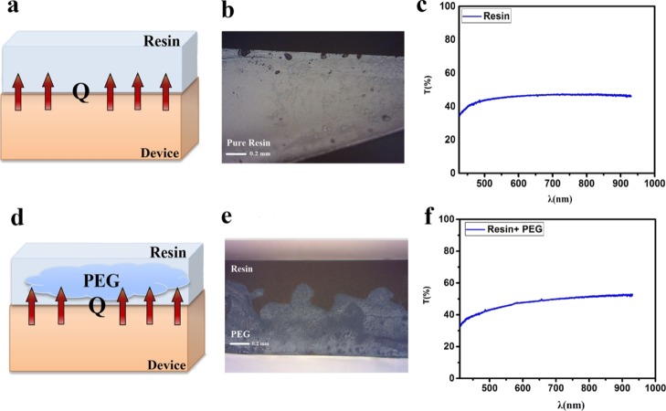
To protect the device against the diffusion of water and oxygen molecules and temperature rise under the operation conditions, the devices are encapsulated using two different systems that are schematically presented in Figure 2. The first is a thin layer of a transparent UV-cured resin that just blocks the diffusion of moisture and oxygen molecules into the devices from the cathode side (Figure 2a). The second is designed not only to block the diffusion of water and oxygen molecules but also to control the device temperature and prevent the temperature rise during the operation under sun illumination (Figure 2d). In this system, poly(ethylene glycol) (PEG) is selected as a suitable PCM that is embedded in the polymer resin. It should be noted that the miscibility of the resin and PEG is considered to design an efficient cooling system with no leakage of PEG during melting under sunlight illumination. In the designed cooling system, resin acts as both a barrier for moisture and oxygen and a chamber for PCM to prevent its molecule leakage during the solid–liquid phase change of PCM. Thus, the curing method is considered to provide the formation of a nonuniform blend of resin and PEG after cross-linking. In this regard, during the photocuring of the epoxy resin under high-power UV light that is illuminated from the top side of the encapsulation layer, PEG molecules migrate to the downside of the layer and separate from the resin layer top surface (Figure 2e). It seems that the fast cross-linking of the resin can also facilitate this phase separation of the resin and PCM through the curing process. The cross-sectional images obtained from optical microscopy clearly show the sealing of PCM by the resin in a 1:1 ratio (Figures 2e and S1). It should be noted that samples encapsulated by the blend of PEG/resin with a 2:1 ratio are damaged after curing because of the PEG leakage (Figure S2). On the other hand, it is desired to add PCM into the cooling system as much as possible. Thus, among the 1:1, 2:1, and 1:2 ratios of PEG/resin, the ratio of 1:1 is chosen as the beneficial amount of PCM in cooling effect.
Figure 2.
(a) Schematic illustration, (b) optical image, and (c) transmission spectrum of the encapsulation system based on pure resin and (d) schematic illustration, (e) optical image, and (f) transmission spectrum of the encapsulation system comprising resin and PEG1000 as cooling agents.
It is worth noting that the transparency of the cooling system is considered in the selection of materials. The transmission spectra of the moisture and temperature protecting systems are exhibited in Figure 2c,f. As observed, the cooling system shows more than 45% transparency of the visible light that is desired for controlling the temperature and stability of the devices. In fact, passing photons through the solar cell modules cannot be ignored, so it would be better to provide a transparent encapsulation layer not to trap the light.
Temperature range and the amount of heat that PEG can absorb during the melting process and release during solidification are the key factors that determine the efficiency of the designed system. The differential scanning calorimetry (DSC) diagrams of the encapsulation systems are employed to estimate the aforementioned thermal behavior of the encapsulation systems. Figures 3a, 4b, S3, and S4 present the DSC diagrams of pure resin, pure PEG, resin/PEG1000, and resin/PEG2000 blends. The extracted data related to the thermal behavior of the systems are summarized in Table 1. No peak is observed in the DSC curve of the pure resin that confirms that the resin is fully photocured. Further, the onset and end points for the melting process in the cooling system containing PEG1000 are at 24 and 36.9 °C, respectively. It can absorb around 54.81 J/g of the released heat from the device, though a higher ΔH can be achieved by changing the sample. Because of the phase separation of the resin and PEG in the designed cooling system, the selection of the sample for DSC analysis is crucial. The melting temperature range for the PEG2000/resin cooling system is 43–60 °C with a melting peak located at 54.7 °C and a melting enthalpy of around 57 J/g. In addition to the heating cycles, the cooling cycles that exhibit the solidification behavior of the systems are also presented in Figures S5 and S6.
Figure 3.
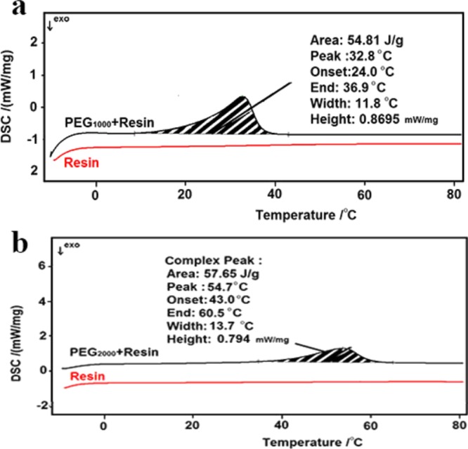
(a) DSC curves of pure resin and resin: PEG1000 encapsulation layers and (b) DSC curves of pure resin and resin/PEG2000 encapsulation layers.
Figure 4.
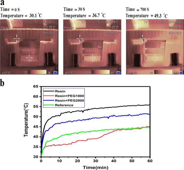
(a) Temperature profile of the devices under operation and (b) temperature–time diagram under 1 sun illumination.
Table 1. Thermal Behavior of the Different Systems Used as Encapsulation Layers.
| type | melting point (°C) | enthalpy of melting J/g |
|---|---|---|
| resin | ||
| PEG1000 | 42.1 | 197.4 |
| PEG1000/resin (1:1) | 32.8 | 54.8 |
| PEG2000 | 55.9 | 203.8 |
| PEG2000/resin (1:1) | 54.7 | 57.7 |
To determine the effect of the designed cooling system on the temperature regulation of the PSCs, four types of devices including reference cell, encapsulated with just the resin cell, encapsulated with resin/PEG1000, and encapsulated with resin/PEG2000 systems are checked thermally under 1 sun illumination (Figure 4a). The trend of the temperature increment in all samples is exhibited in Figure 4a,b. As observed, the maximum temperatures for the reference device, encapsulated devices by the resin, resin/PEG1000, and resin/PEG2000 are 41.2, 49.3, 36.6, and 46.9 °C, respectively. Remarkably, the lowest and highest temperature differences are observed for the devices encapsulated by the resin/PEG1000 blend and just resin that are around 7 and 19 °C, respectively. In fact, the heat generated in the device during the operation is trapped in the encapsulated device because of the insulation feature of the polymer resin (the thermal conductivity of epoxy resin is around 0.2 W/mK) that is confirmed by observing the fastest temperature rise and the maximum temperature for the device encapsulated with just resin (Figure 4, Table 2). As observed in Figure 4c, the temperature of the device encapsulated by resin/PEG1000 shows an ascending trend after 35 min that indicates the full melting of PCM. Thus, the heat trapping is an issue in almost all optoelectronic devices encapsulated by the polymer resin that is the widely utilized method for the device protecting against moisture and oxygen molecules. Actually, the performance (η) of the devices is strongly dependent on the operation temperature through the following relations reported in the literature (eq 1).35
| 1 |
where T and η are the temperature and PCE, respectively, and βref is the temperature coefficient of the PV module. It should be noted that these relations reported for traditional solar cell modules and the performance loss through the degradation of the device components have not been considered.
Table 2. Thermal Behavior of the Encapsulated Devices.
| device | initial slope | ΔT (°C) t = 11 min |
|---|---|---|
| just resin | 0.162 | 19 |
| resin and PEG2000 | 0.128 | 17 |
| reference | 0.048 | 12 |
| resin and PEG1000 | 0.028 | 7 |
Moreover, comparison of the thermal behavior of the devices encapsulated by resin/PEG1000 and resin/PEG2000 reveals that the resin/PEG2000 system is not as much efficient as the resin/PEG1000 system in the temperature controlling of the device that is attributed to the melting temperature range of the last one obtained from the DSC curve. In fact, the melting point of PEG2000 is 55 °C that is higher than the maximum operating temperature of the PSCs (Figures S3–S6). As shown, by using a suitable PCM and structure, the temperature increase of the device under sun illumination, especially through the hours of a day when the sun intensity is high, can be prevented efficiently.
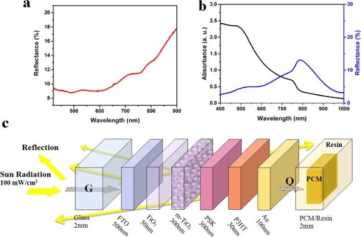
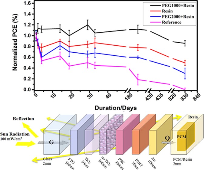
In fact, the optical and electrical losses during the PV process act as the source of the heat generated in the device. Because the layer thicknesses in PSCs are comparable with the wavelength of the incident photons, the optical interference effects play an important role in the multilayer structure behavior that determine the final light absorption efficiency and loss in the device. As presented in Figure 5a, around 15% of the incident light (100 mW/cm2) is reflected from the FTO side. Thus, the incident energy (Ġ) into the fabricated device is around 85 mW/cm2. Further, the CH3NH3PbI3 layer in this device absorbs around 50% of the incident light that is approximately equal to 40 mW/cm2. The achieved 10% efficiency for the device reveals that around 10% of the absorbed light is converted into electricity and the rest is lost optically and electrically through the charge recombination that acts as the heat source. Accordingly, the energy balance in the device can be written as
| 2 |
| 3 |
where Ėelectrical is the electrical energy generated in the device and Q̇loss is the thermal energy generated by optical and electrical losses. Q̇loss is a combination of the thermal energy stored in the device and the released thermal energy from the device that is considered to be managed by the cooling system. As stated, the optical and electrical analyses reveal that around 75% of the incident light is lost. It proves the importance of thermal energy management in these devices, especially organic-based ones.
Figure 5.
(a) Total reflection of the incident light from the FTO side of the complete device, (b) absorption and reflection of the perovskite layer, and (c) schematic of the energy conversion in the device layers.
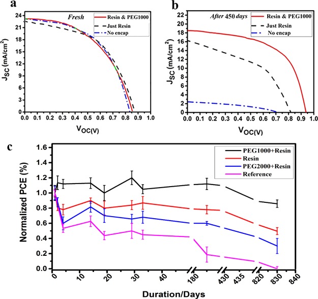
To evaluate the effect of the new designed protecting system on the lifetime of PSCs, several solar cells are fabricated at the same time and conditions and subsequently encapsulated. Figure 6C presents the normalized performance of the devices during 830 days of storage under the ambient condition with a 28% RH. Figures 6a,b and S7 show the J–V characteristics of the nonencapsulated, resin-encapsulated, and resin-/PCM-encapsulated devices before and after the aging process for 450 and 830 days under the ambient condition. Also, the extracted PV characteristics are summarized in Table 3. Surprisingly, the device protected by the moisture- and oxygen-blocked and cooling system containing a resin/PEG1000 mixture shows no significant loss in its PCE. The pure resin-encapsulated device shows about 30 and 50% reduction in its performance after 450 and 830 days, respectively (Figure 6c), while the unencapsulated device suffers from more than 50% reduction in its PCE after just 10 days of storage under the ambient condition. As clearly observed, the device encapsulated by resin/PEG2000 is not as much efficient as resin/PEG 1000 that can be attributed to the undesired temperature range confirmed by the DSC curve (Figure 3). Moreover, the resin-/PEG1000-encapsulated device shows better stability under continuous illumination compared to the reference device (Figure S9). Figure S8 presents the stability behavior of the reference device and encapsulated device kept under a RH of 85% that confirms the efficient moisture blocking effect of the encapsulation system. The enhancement of PCE and changes occurring in the J–V characteristics of the devices through the storage can be related to the passivation of the available defects in the structures. In the perovskite materials, an anionic Pb–I antisite defect on a PbI2-terminated surface and a cationic Pb cluster on a MAI-terminated surface were defined as two surface defect sites to generate deep charge traps.36 On the other hand, it was known that during the formation and storage of the perovskite layer, halides and cations are lost from the perovskite crystal, resulting in undercoordinated Pb atoms on both the surface and grain boundaries of the film and vacancy sites are formed that act as electronic trap sites.37 Because the resin used for encapsulation of the device was cured by high-power UV, it seems that the UV light inserts into the perovskite layer and passivates the surface defects and grain boundary defects by dissociating adsorbed hydroxyl groups and water molecules in the device. It is proposed that under UV irradiation, the adsorbed water molecules can be dissociated into the oxygen, hydrogen, and hydroxyl radicals that can passivate the dangling bonds in the perovskite crystals.38 Another possible mechanism for the observed behavior is related to the presence of oxygen molecules in the bulk and interfaces of the perovskite device that were adsorbed during the device fabrication and encapsulation. As reported, the oxygen molecules can efficiently passivate the available defect sites in the perovskite materials.39
Figure 6.
(a,b) J–V characteristics of the unencapsulated device, pure resin-encapsulated device, and moisture-blocked and temperature-controlled encapsulated device in fresh condition and after 450 days of storage. (c) Statistical normalized PCE of the devices during 830 days of storage under the ambient condition with a 28% RH.
Table 3. PV Characteristics Extracted from J–V Curves Presented in Figure 6.
| device | Jsc (mA/cm2) | Voc (V) | FF | PCE (%) | Rs (Ω cm2) | Rsh (Ω cm2) | |
|---|---|---|---|---|---|---|---|
| fresh | Unencapsulated | 23.21 | 0.83 | 0.53 | 10.16 | 8.7 | 375.9 |
| just resin | 22.62 | 0.87 | 0.52 | 10.25 | 9.3 | 200.8 | |
| resin and PEG1000 | 23.22 | 0.85 | 0.5 | 10 | 9.3 | 500 | |
| after 450 days | Unencapsulated | 2.40 | 0.7 | 0.2 | 0.34 | 123.6 | 689 |
| just resin | 16.25 | 0.81 | 0.46 | 6.03 | 17.6 | 117.6 | |
| resin and PEG1000 | 18.52 | 0.93 | 0.58 | 10.01 | 7.8 | 1282 | |
| after 830 days | Unencapsulated | 0.079 | 0.9 | 0.21 | 0.015 | 15777 | 8241 |
| just resin | 18.71 | 0.65 | 0.38 | 4.52 | 17.87 | 120 | |
| resin and PEG1000 | 18.99 | 0.92 | 0.45 | 7.9 | 7.8 | 101 | |
To understand the electrical changes in the encapsulated device during the storage, the impedance spectra of the fresh device and stored device for 450 days are recorded under illumination at open-circuit condition. Besides, the impedance spectrum of the fresh device without encapsulation is depicted in Figure S10. To extract the device parameters, the spectra are fitted by the equivalent circuit presented in Figure 7. In this model, the high-frequency arc is fitted by resistance R1 coupled to capacitance C1. The low-frequency arc is fitted by C2 and R2 that represent the parameters associated with the contact to the perovskite. Capacitances and resistances extracted by fitting the equivalent circuit model are summarized in Tables 4 and S1. No significant change is observed in the electrical properties after 450 days of storage. C2 which is due to the diverse dipolar mechanisms such as CH3NH3+ or PbI6 octahedra reorientation,40 and cooperative ionic off-centering, decreases after 450 days of storage. The low-frequency capacitance (C2) is associated with the electronic and ionic accumulation at the electrode interfaces.40 Further, the recombination resistance (R2) of the device after 450 days is slightly higher than that in the fresh condition. It can be concluded that the protection of the device from moisture and temperature rise inhibits the degradation of the materials and accumulation of defect sites in the bulk and the interfaces. The semicircle observed in the higher frequency region can be related to the charge transport (R1) of the HTL, ETL, and their interfaces with the PSK active layer and extraction in the Au contact. As reported in Table 4, there is no significant change in R1 of the fresh and aged devices because of the same structure.
Figure 7.
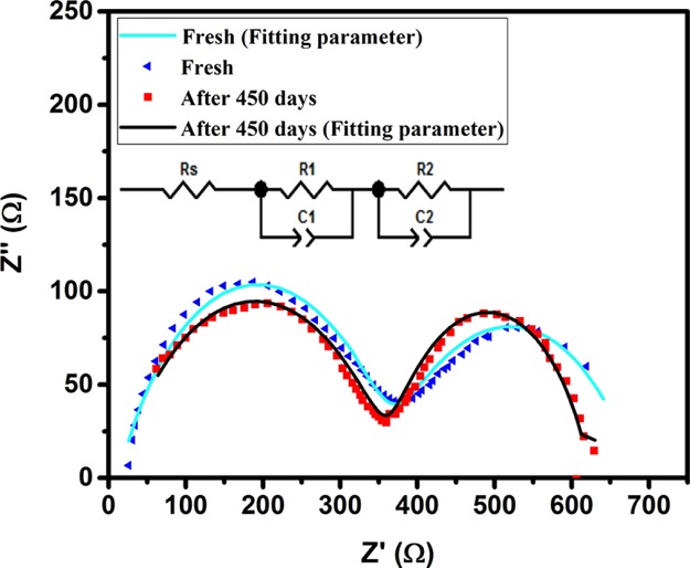
Impedance spectra of the device encapsulated by the resin/PEG1000 blend in fresh condition and after 450 days of storage in ambient conditions. The inset shows the equivalent electrical circuit model used for data fitting.
Table 4. Electrical Properties of the Fresh Devices and Stored Devices for 450 Days.
| device | Rs (Ω) | R1 (Ω) | R2 (Ω) | C1 (F) | C2 (F) |
|---|---|---|---|---|---|
| fresh | 10 | 355.6 | 290 | 4.16 × 10⁻⁸ | 1.84 × 10⁻³ |
| after 450 days | 13 | 350.5 | 320.6 | 2.45 × 10⁻⁸ | 9.1 × 10⁻⁵ |
Conclusions
In summary, a new moisture- and oxygen-blocked and temperature-controlled encapsulation system was designed based on polymer resin/PCM to prolong the lifetime of the perovskite devices and prevent the crystalline phase transition. This system included the polymer resin as the moisture and oxygen barrier and PEG molecules as the temperature adjuster. Surprisingly, the device encapsulated with the designed protecting system (resin/PEG1000) retained its initial performance after 450 days of storage, while the resin encapsulated showed 20% decrease in its initial PCE and the unencapsulated device lost its performance completely in this period of time. It was evidenced that the resin encapsulation system that is widely used in the optoelectronic devices acts as a barrier for releasing the heat produced because of the optical and electrical losses during the device operation. In this regard, the device encapsulated by pure resin reached the highest temperature compared to the unencapsulated device, encapsulated with resin/PEG1000, and resin/PEG2000. Remarkably, the lowest temperature rise during the operation of the device was resulted for the resin/PEG100 encapsulation system because of the suitable thermal design. The desirable protection of the devices by the resin/PEG1000 encapsulation system was confirmed by the electrical analysis that showed no significant changes in the recombination and transport resistances after 450 days of storage.
Experimental Section
Solar Cell Fabrication
To fabricate PSCs, FTO-coated glass substrates are etched and cleaned with deionized water, acetone, and isopropanol, respectively. After drying the substrates at 100 °C for 30 min, they are coated with a compact blocking layer of TiO2 (bl-TiO2) by spin-coating a mild acidic solution of tetraisopropyl orthotitanate in ethanol, followed by annealing at 500 °C for 30 min. The compact layer is treated by TiCl4 solution and annealed at 500 °C for 30 min. Then, the mesoporous TiO2 (mp-TiO2) layer is deposited by spin-coating the TiO2 paste at 5000 rpm for 30 s and annealed at 500 °C for 30 min. After the treatment of the TiO2 layer by TiCl4, as already described, the perovskite layer is deposited on it via a two-step process from the PbI2 precursor solution (1 M in anhydrous dimethylformamide) and CH3NH3I solution (7 mg/mL in anhydrous isopropyl alcohol) by a spin-coating method. Poly-3-hexylthiophene (P3HT) is used as the HTL that is spin-coated from 10 mg/mL solution of P3HT in chlorobenzene. Finally, a 100 nm thick Au layer is deposited on top of the P3HT film by a thermal evaporator (Nanostructure Coating Co. Iran) in vacuum (∼10–5 torr), yielding an active area of 0.11 cm2.
Solar Cell Encapsulation
To encapsulate the devices, a UV-curable epoxy-based resin (lab made) is used as both the moisture and oxygen barrier and as a matrix for PCM. According to the operational conditions of PSCs, PEG1000 and PEG2000 (produced by Merck Company) are employed as PCMs. Thus, first, PEG is heated at 45 °C to melt, and then resin is added. The blends of resin and PCM with various compositions are stirred for 1 h at 45 °C. To define the maximum useable percentage of PCM, three blends comprising 1:2, 1:1, and 2:1 weight ratios of PEG/resin are prepared based on the miscibility behavior of the PEG/resin mixture.41 To prevent the corrosion of the devices because of the direct contact with the PEG molecules, the device is first covered by a thin layer (500 μm) of the pure resin, and then a layer of the PEG: resin blend with a thickness of around 1 mm was added as the moisture and heat protecting system. The deposition of the resin layers is performed using a soft brush where the thickness is controlled by the resin weight per device area. All curing processes are performed under UV light with λ = 400 nm for 4 min. In the case of the encapsulated devices with resin, only one layer of the resin is covered on the device and cured.
Characterization
The morphology and structure of the films are characterized using Phenom scanning electron microscopy (SEM) and field emission SEM (TESCAN). Besides, a Veeco atomic force microscope (CP-Research, USA) is used to take perovskite layer surface topography images. The absorption and transmission spectra of the device layers are recorded by an Avantes UV–visible spectrophotometer (AvaSpec 2048, Netherland). In order to investigate the crystalline nature of the perovskite film, the X-ray diffraction spectrum is obtained on a Philips diffractometer (model: X’Pert MPD) equipped with a proportional Xe-filled detector, Cu tube (λ = 1.54056 Å). Current–voltage (I–V) characteristics of the fabricated devices are measured by an Ivium stat potentiostat (XRE model, Netherland) under a calibrated AM 1.5 solar simulator at 100 mW/cm2 light intensity (Sharif Solar 10-2, Iran). An IVIUM stat potentiostat/galvanostat (XRE model, Netherland) is also utilized to record the impedance spectra of the devices in the frequency range of 1–100 KHz under light and bias V = 0 V. Thermal analysis of the encapsulation systems is performed by DSC (NETZSCH 200F). Further, the temperature profiles of the PSCs under the operation condition are recorded by a thermography camera (model: OLIP ThermoCam P200).
Acknowledgments
The authors would like to acknowledge the financial support from Iran National Science Foundation (INSF) and the research department of Tarbiat Modares University (Research group of PCMs, grant no. IG-39710 and research group of nano plasma photonic, IG-39704).
Supporting Information Available
The Supporting Information is available free of charge at https://pubs.acs.org/doi/10.1021/acsomega.9b03407.
DSC curves of the encapsulation systems and images of the device degradation through undesired encapsulation (PDF)
The authors declare no competing financial interest.
Supplementary Material
References
- Arabpour Roghabadi F.; Ahmadi N.; Ahmadi V.; Di Carlo A.; Oniy Aghmiuni K.; Shokrolahzadeh Tehrani A.; Ghoreishi F. S.; Payandeh M.; Mansour Rezaei Fumani N. Bulk heterojunction polymer solar cell and perovskite solar cell: Concepts, materials, current status, and opto-electronic properties. Sol. Energy 2018, 173, 407–424. 10.1016/j.solener.2018.07.058. [DOI] [Google Scholar]
- Kojima A.; Teshima K.; Shirai Y.; Miyasaka T. Organometal Halide Perovskites as Visible-Light Sensitizers for Photovoltaic Cells. J. Am. Chem. Soc. 2009, 131, 6050–6051. 10.1021/ja809598r. [DOI] [PubMed] [Google Scholar]
- NREL . http://www.nrel.gov/pv/assets/images/efficiency-chart-20190716.
- Zhang F.; Xiao C.; Chen X.; Larson B. W.; Harvey S. P.; Berry J. J.; Zhu K. Self-Seeding Growth for Perovskite Solar Cells with Enhanced Stability. Joule 2019, 3, 1452–1463. 10.1016/j.joule.2019.03.023. [DOI] [Google Scholar]
- Roghabadi F. A.; Alidaei M.; Mousavi S. M.; Ashjari T.; Tehrani A. S.; Ahmadi V.; Sadrameli S. M. Stability progress of perovskite solar cells dependent on the crystalline structure: From 3D ABX3 to 2D Ruddlesden–Popper perovskite absorbers. J. Mater. Chem. A 2019, 7, 5898–5933. 10.1039/c8ta10444a. [DOI] [Google Scholar]
- Chung J.; Shin S. S.; Kim G.; Jeon N. J.; Yang T.-Y.; Noh J. H.; Seo J. Impact of Electrode Materials on Process Environmental Stability of Efficient Perovskite Solar Cells. Joule 2019, 3, 1977. 10.1016/j.joule.2019.05.018. [DOI] [Google Scholar]
- Yang J.; Siempelkamp B. D.; Liu D.; Kelly T. L. Investigation of CH3NH3PbI3 degradation rates and mechanisms in controlled humidity environments using in situ techniques. ACS Nano 2015, 9, 1955–1963. 10.1021/nn506864k. [DOI] [PubMed] [Google Scholar]
- Zhao J.; Cai B.; Luo Z.; Dong Y.; Zhang Y.; Xu H.; Hong B.; Yang Y.; Li L.; Zhang W. Investigation of the hydrolysis of perovskite organometallic halide CH3NH3PbI3 in humidity environment. Sci. Rep. 2016, 6, 21976. 10.1038/srep21976. [DOI] [PMC free article] [PubMed] [Google Scholar]
- Divitini G.; Cacovich S.; Matteocci F.; Cina L.; Di Carlo A.; Ducati C. In situ observation of heat-induced degradation of perovskite solar cells. Nat. Energy 2016, 1, 15012. 10.1038/nenergy.2015.12. [DOI] [Google Scholar]
- Conings B.; Drijkoningen J.; Gauquelin N.; Babayigit A.; D’Haen J.; D’Olieslaeger L.; Ethirajan A.; Verbeeck J.; Manca J.; Mosconi E. Intrinsic thermal instability of methylammonium lead trihalide perovskite. Adv. Energy Mater. 2015, 5, 1500477. 10.1002/aenm.201500477. [DOI] [Google Scholar]
- Leijtens T.; Eperon G. E.; Pathak S.; Abate A.; Lee M. M.; Snaith H. J. Overcoming ultraviolet light instability of sensitized TiO2 with meso-superstructured organometal tri-halide perovskite solar cells. Nat. Commun. 2013, 4, 2885. 10.1038/ncomms3885. [DOI] [PubMed] [Google Scholar]
- Pockett A.; Raptis D.; Meroni S. M. P.; Baker J.; Watson T.; Carnie M. Origin of Exceptionally Slow Light Soaking Effect in Mesoporous Carbon Perovskite Solar Cells with AVA Additive. J. Phys. Chem. C 2019, 123, 11414–11421. 10.1021/acs.jpcc.9b01058. [DOI] [Google Scholar]
- Boopathi K. M.; Mohan R.; Huang T.-Y.; Budiawan W.; Lin M.-Y.; Lee C.-H.; Ho K.-C.; Chu C.-W. Synergistic improvements in stability and performance of lead iodide perovskite solar cells incorporating salt additives. J. Mater. Chem. A 2016, 4, 1591–1597. 10.1039/c5ta10288j. [DOI] [Google Scholar]
- Meng L.; Zhang F.; Ma W.; Zhao Y.; Zhao P.; Fu H.; Wang W.; Meng S.; Guo X. Improving Photovoltaic Stability and Performance of Perovskite Solar Cells by Molecular Interface Engineering. J. Phys. Chem. C 2019, 123, 1219–1225. 10.1021/acs.jpcc.8b09722. [DOI] [Google Scholar]
- Asghar M. I.; Zhang J.; Wang H.; Lund P. D. Device stability of perovskite solar cells–a review. Renew. Sustain. Energy Rev. 2017, 77, 131–146. 10.1016/j.rser.2017.04.003. [DOI] [Google Scholar]
- Zhao X.; Park N.-G. Stability Issues on Perovskite Solar Cells. Photonics 2015, 2, 1139. 10.3390/photonics2041139. [DOI] [Google Scholar]
- Dualeh A.; Tétreault N.; Moehl T.; Gao P.; Nazeeruddin M. K.; Grätzel M. Effect of Annealing Temperature on Film Morphology of Organic–Inorganic Hybrid Pervoskite Solid-State Solar Cells. Adv. Funct. Mater. 2014, 24, 3250–3258. 10.1002/adfm.201304022. [DOI] [Google Scholar]
- Raga S. R.; Jung M.-C.; Lee M. V.; Leyden M. R.; Kato Y.; Qi Y. Influence of Air Annealing on High Efficiency Planar Structure Perovskite Solar Cells. Chem. Mater. 2015, 27, 1597–1603. 10.1021/cm5041997. [DOI] [Google Scholar]
- Eperon G. E.; Habisreutinger S. N.; Leijtens T.; Bruijnaers B. J.; van Franeker J. J.; deQuilettes D. W.; Pathak S.; Sutton R. J.; Grancini G.; Ginger D. S.; Janssen R. A. J.; Petrozza A.; Snaith H. J. The Importance of Moisture in Hybrid Lead Halide Perovskite Thin Film Fabrication. ACS Nano 2015, 9, 9380–9393. 10.1021/acsnano.5b03626. [DOI] [PubMed] [Google Scholar]
- Gong X.; Li M.; Shi X.-B.; Ma H.; Wang Z.-K.; Liao L.-S. Controllable Perovskite Crystallization by Water Additive for High-Performance Solar Cells. Adv. Funct. Mater. 2015, 25, 6671–6678. 10.1002/adfm.201503559. [DOI] [Google Scholar]
- Noh J. H.; Im S. H.; Heo J. H.; Mandal T. N.; Seok S. I. Chemical Management for Colorful, Efficient, and Stable Inorganic–Organic Hybrid Nanostructured Solar Cells. Nano Lett. 2013, 13, 1764–1769. 10.1021/nl400349b. [DOI] [PubMed] [Google Scholar]
- Stoumpos C. C.; Malliakas C. D.; Kanatzidis M. G. Semiconducting Tin and Lead Iodide Perovskites with Organic Cations: Phase Transitions, High Mobilities, and Near-Infrared Photoluminescent Properties. Inorg. Chem. 2013, 52, 9019–9038. 10.1021/ic401215x. [DOI] [PubMed] [Google Scholar]
- Kay H. F.; Bailey P. C. Structure and properties of CaTiO3. Acta Crystallogr. 1957, 10, 219–226. 10.1107/s0365110x57000675. [DOI] [Google Scholar]
- Lee Y. I.; Jeon N. J.; Kim B. J.; Shim H.; Yang T.-Y.; Seok S. I.; Seo J.; Im S. G. A Low-Temperature Thin-Film Encapsulation for Enhanced Stability of a Highly Efficient Perovskite Solar Cell. Adv. Energy Mater. 2018, 8, 1701928. 10.1002/aenm.201701928. [DOI] [Google Scholar]
- Decker C.; Keller L.; Zahouily K.; Benfarhi S. Synthesis of nanocomposite polymers by UV-radiation curing. Polymer 2005, 46, 6640–6648. 10.1016/j.polymer.2005.05.018. [DOI] [Google Scholar]
- Bauer F.; Flyunt R.; Czihal K.; Langguth H.; Mehnert R.; Schubert R.; Buchmeiser M. R. UV curing and matting of acrylate coatings reinforced by nano-silica and micro-corundum particles. Prog. Org. Coat. 2007, 60, 121–126. 10.1016/j.porgcoat.2007.07.005. [DOI] [Google Scholar]
- Han Y.; Meyer S.; Dkhissi Y.; Weber K.; Pringle J. M.; Bach U.; Spiccia L.; Cheng Y.-B. Degradation observations of encapsulated planar CH 3 NH 3 PbI 3 perovskite solar cells at high temperatures and humidity. J. Mater. Chem. A 2015, 3, 8139–8147. 10.1039/c5ta00358j. [DOI] [Google Scholar]
- Dong Q.; Liu F.; Wong M. K.; Tam H. W.; Djurišić A. B.; Ng A.; Surya C.; Chan W. K.; Ng A. M. C. Encapsulation of perovskite solar cells for high humidity conditions. ChemSusChem 2016, 9, 2597–2603. 10.1002/cssc.201600868. [DOI] [PubMed] [Google Scholar]
- Matteocci F.; Cinà L.; Lamanna E.; Cacovich S.; Divitini G.; Midgley P. A.; Ducati C.; Di Carlo A. Encapsulation for long-term stability enhancement of perovskite solar cells. Nano Energy 2016, 30, 162–172. 10.1016/j.nanoen.2016.09.041. [DOI] [Google Scholar]
- Zuo L.; Guo H.; deQuilettes D. W.; Jariwala S.; De Marco N.; Dong S.; DeBlock R.; Ginger D. S.; Dunn B.; Wang M.; Yang Y. Polymer-modified halide perovskite films for efficient and stable planar heterojunction solar cells. Sci. Adv. 2017, 3, e1700106 10.1126/sciadv.1700106. [DOI] [PMC free article] [PubMed] [Google Scholar]
- Tripathi N.; Yanagida M.; Shirai Y.; Masuda T.; Han L.; Miyano K. Hysteresis-free and highly stable perovskite solar cells produced via a chlorine-mediated interdiffusion method. J. Mater. Chem. A 2015, 3, 12081–12088. 10.1039/c5ta01668a. [DOI] [Google Scholar]
- Lau C. F. J.; Deng X.; Zheng J.; Kim J.; Zhang Z.; Zhang M.; Bing J.; Wilkinson B.; Hu L.; Patterson R.; Huang S.; Ho-Baillie A. Enhanced performance via partial lead replacement with calcium for a CsPbI3 perovskite solar cell exceeding 13% power conversion efficiency. J. Mater. Chem. A 2018, 6, 5580–5586. 10.1039/c7ta11154a. [DOI] [Google Scholar]
- Teo H. G.; Lee P. S.; Hawlader M. N. A. An active cooling system for photovoltaic modules. Appl. Energy 2012, 90, 309–315. 10.1016/j.apenergy.2011.01.017. [DOI] [Google Scholar]
- Norton B.Use of Heat From, and Thermal Management of, Photovoltaics. Harnessing Solar Heat; Springer Netherlands: Dordrecht, 2014; pp 115–122. [Google Scholar]
- Charles Lawrence Kamuyu W.; Lim J.; Won C.; Ahn H. Prediction Model of Photovoltaic Module Temperature for Power Performance of Floating PVs. Energies 2018, 11, 447. 10.3390/en11020447. [DOI] [Google Scholar]
- Zheng X.; Chen B.; Dai J.; Fang Y.; Bai Y.; Lin Y.; Wei H.; Zeng X. C.; Huang J. Defect passivation in hybrid perovskite solar cells using quaternary ammonium halide anions and cations. Nat. Energy 2017, 2, 17102. 10.1038/nenergy.2017.102. [DOI] [Google Scholar]
- Noel N. K.; Abate A.; Stranks S. D.; Parrott E. S.; Burlakov V. M.; Goriely A.; Snaith H. J. Enhanced photoluminescence and solar cell performance via Lewis base passivation of organic–inorganic lead halide perovskites. ACS Nano 2014, 8, 9815–9821. 10.1021/nn5036476. [DOI] [PubMed] [Google Scholar]
- Roghabadi F. A.; Fumani N. M. R.; Alidaei M.; Ahmadi V.; Sadrameli S. M. High power UV-Light Irradiation as a New Method for Defect passivation in Degraded perovskite solar Cells to Recover and enhance the performance. Sci. Rep. 2019, 9, 9448. 10.1038/s41598-019-45756-1. [DOI] [PMC free article] [PubMed] [Google Scholar]
- Anaya M.; Galisteo-López J. F.; Calvo M. E.; Espinós J. P.; Míguez H. Origin of light-Induced photophysical effects in organic metal halide perovskites in the presence of oxygen. J. Phys. Chem. Lett. 2018, 9, 3891–3896. 10.1021/acs.jpclett.8b01830. [DOI] [PubMed] [Google Scholar]
- Guerrero A.; Garcia-Belmonte G.; Mora-Sero I.; Bisquert J.; Kang Y. S.; Jacobsson T. J.; Correa-Baena J.-P.; Hagfeldt A. Properties of contact and bulk impedances in hybrid lead halide perovskite solar cells including inductive loop elements. J. Phys. Chem. C 2016, 120, 8023–8032. 10.1021/acs.jpcc.6b01728. [DOI] [Google Scholar]
- Qin C.; Shen J.; Hu Y.; Huang W.; Ye M. Miscibility, crystallization behavior and specific intermolecular interactions in thermosetting polymer blends of novolac epoxy resin and polyethylene glycol. Polym. Eng. Sci. 2008, 48, 556–563. 10.1002/pen.20966. [DOI] [Google Scholar]
Associated Data
This section collects any data citations, data availability statements, or supplementary materials included in this article.


