Abstract
In this article, we present a novel stochastic algorithm called simultaneous sensor calibration and deformation estimation (SCADE) to address the problem of modeling deformation behavior of a generic continuum manipulator (CM) in free and obstructed environments. In SCADE, using a novel mathematical formulation, we introduce a priori model-independent filtering algorithm to fuse the continuous and inaccurate measurements of an embedded sensor (e.g., magnetic or piezoelectric sensors) with an intermittent but accurate data of an external imaging system (e.g., optical trackers or cameras). The main motivation of this article is the crucial need of obtaining an accurate shape/position estimation of a CM utilized in a surgical intervention. In these robotic procedures, the CM is typically equipped with an embedded sensing unit (ESU) while an external imaging modality (e.g., ultrasound or a fluoroscopy machine) is also available in the surgical site. The results of two different set of prior experiments in free and obstructed environments were used to evaluate the efficacy of SCADE algorithm. The experiments were performed with a CM specifically designed for orthopaedic interventions equipped with an inaccurate Fiber Bragg Grating (FBG) ESU and overhead camera. The results demonstrated the successful performance of the SCADE algorithm in simultaneous estimation of unknown deformation behavior of the utilized unmodeled CM together with realizing the time-varying drift of the poor-calibrated FBG sensing unit. Moreover, the results showed the phenomenal out-performance of the SCADE algorithm in estimation of the CM’s tip position as compared to FBG-based position estimations.
Keywords: Continuum manipulators (CMs), fiber Bragg grating (FBG) sensor, medical robots and systems, sensor fusion
I. Introduction
CONTINUUM manipulators (CMs) and robots utilizing flexible instruments (FIs) (e.g., needles and catheters) have recently garnered attention due to their superior dexterity and enhanced accessibility in performing minimally invasive surgeries. Examples of these robotic systems include the use of an ablation catheter for treatment of atrial fibrillation [1], needle inserting robots for venipuncture [2], and brachytherapy [3]. Additionally, continuum robots have been deployed in endonasal skull base surgery [4], cardiac [5], and natural orifice transluminal endoscopic surgery [6]. Despite the advantages of using CMs/FIs, real-time control of these systems in unstructured environments is a challenging problem. In particular, these challenges include the following:
-
1)
an accurate and robust sensing system (external or embedded), which can undergo and capture large deflections;
-
2)
pertinent robust model-based or model-independent algorithm to estimate their shape and tip position on the fly;
-
3)
an adaptive model-based or model-independent control paradigm to accurately control various type of CMs/FIs in an unknown and obstructed environment [7].
Of note, the success of both shape/tip sensing and control algorithms depends on the efficacy of the utilized deformation model for CMs/FIs. Therefore, adaptive and versatile CM/FI deformation estimation approaches need to be developed that can be easily implemented using various types of external and embedded sensing modalities.
A. Prior Work
Various methods have been proposed in the literature for modeling and estimation of the deformation behavior of CMs and FIs. First group of methods is model-based approaches. This group typically utilizes analytical or computational methods (e.g., finite element) to model the deformation behavior of these flexible devices in free or obstructed environments. For instance, the literature reports various kinematics- or dynamics-based modeling approaches for CM/FI shape/tip estimations in free and obstructed environments (e.g., [3], [8]–[12]). The performance of this model-based methodology, however, does dramatically depend on the accuracy of the developed model and the assumptions made during the modeling procedure [13]. Due to the uncertainties caused by hysteresis, friction, backlash, and interaction with an unknown environment, a discrepancy between the expected and the actual behavior is typically observed in this group of modeling [9], [14], [15]. Moreover, these model-based approaches are often system specific and application specific, and are not easily extendable to the other forms of CMs/FIs.
Second group of studies is related to sensor-based deformation estimation using an external or embedded sensing unit (ESU). Examples of deployed external sensing units are infrared optical trackers, cameras, and medical imaging modalities such as fluoroscopy, ultrasound, and magnetic resonance imaging (MRI). Examples of embedded units include electromagnetic trackers, piezoelectric polymers, and recently fiber Bragg grating (FBG) optical sensors [16]. Each of these sensing units suffers from major shortcomings. For example, optical trackers and cameras typically have line-of-sight and occlusion issues [17]. Imaging modalities such as X-ray suffer from a large amount of radiation exposure, which limits their real-time use [18]. Magnetic trackers [19] and piezoelectric polymers [20] suffer from the presence of metals and hysteresis, respectively. More recently, FBG sensors have gained popularity due to their great features such as biocompatibility, small size, flexibility, and real-time feedback without requiring a direct line of sight. However, arduous and often manual sensor-assembly and fabrication procedure together with offline static calibration procedure are some of the shortcomings of this ESU [16]. These issues result in an uncertain change and drift in the offline calibration parameters of FBG sensors, which are mainly due to the discrepancy between the calibration procedure and the actual implementation of FBG-equipped CM/FIs [21], [22]. While calibration is usually performed in a free environment with no obstacle, the real-world applications might involve interaction of CM/FIs with an obstructed environment. This may result in large uncalibrated deformation behaviors as well as dynamic bending motions, which may lead to a poor shape/position estimation [16], [21], [23].
Online filtering using an embedded electromagnetic tracking sensor has also been proposed for estimating the shape and end-effector pose of CMs. Using this model-based Kalman filter (KF) approach, Tully et al. [24] have shown that a single embedded sensor is sufficient for estimating the shape of a particular type of CM. However, the accuracy of the presented estimation approach might be adversely affected if the robot is acting upon a deformable or moving tissue. Recently, a data-driven and machine-learning-based approach has also been deployed to understand the deformation behavior of a CM/FI equipped with embedded FBG sensors [25]. However, the proposed method has only been trained and evaluated for a particular obstacle-free environment. Moreover, performance of this method is dramatically dependent on the training dataset, which is usually difficult and time-consuming to collect.
To address these issues, third group of studies has used model-based sensor fusion techniques to fuse the data streamed from two sensing units. For instance, to remedy the noisy measurements of sensors, Sadjadi et al. [26] used a Kalman filtering approach to fuse a kinematic needle deflection model with the position measurements of two embedded sensors (i.e., electromagnetic trackers) located at the base and the tip of the needle. The performance of this model-based technique was evaluated using extensive simulations. Recently, Jiang et al. [27] have extended this KF-based sensor fusion approach by using measured data to estimate the tip position of a needle. They deployed an external optical sensor at the base and an embedded electromagnetic sensor in the middle of the semirigid needle. Despite encouraging results, both methods require continuous stream of data from both sensing units during the experiment and rely on a priori kinematics model of the needle. Last but not least, in a series of studies [28]–[30], combinations of a custom-designed electromagnetic sensing module with inertial measurement units (IMUs), an optical tracker with an electromagnetic system, and an optical tracker with an IMU for motion tracking in surgical interventions, respectively, are deployed. Similar to other studies, however, their formulations relied on a priori model for the state evolution and a typical sensor fusion technique.
B. Motivation and Contribution
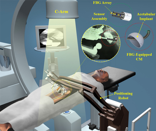
With the goal of enhancing dexterity and accuracy in or-thopedics, the focus of our group is on developing a surgical robotic system for treatment of various orthopedics problems (e.g., removing osteolytic lesions behind the hip acetabular implant [31] and treatment of osteonecrosis of femoral head [32], [33]) using a custom-designed continuum robot called “ortho-snake” (see Fig. 1). While conventional CMs (e.g., [4] and [34]) are commonly designed to interact with soft tissues, ortho-snake, thanks to its structural stability, can robustly interact with hard tissues and bear high external loads during bone milling [35] and drilling [32], [33]. As shown in Fig. 1, in this surgical system, ortho-snake and its actuation unit are integrated with a positioning robotic arm and simultaneously controlled to perform the assigned control objective. To accurately estimate the shape and tip of the ortho-snake in real time, this CM has been equipped with two embedded shape sensors with three FBG sensing nodes that pass through channels within the walls of the CM [21]. Similar to various surgical interventions, the shape and position of the CM inside the patient’s body can also be captured using an external imaging modality (i.e., intraoperative fluoroscopy of an on-site C-arm machine) [18]. Previous efforts of our group for deformation estimation and shape sensing of ortho-snake include developing models for estimating the shape from cable-length measurements [36], the intermittent use of fluoroscopic images for updating a CM model [18], and static [21] and dynamic [23] shape sensing of ortho-snake using FBG sensors in free and obstructed environments. Despite the promising results of these studies, they suffer from aforementioned limitations, which may jeopardize patient’s safety in a real clinical intervention.
Fig. 1.
Conceptual illustration of the proposed robotic workstation for orthopedic applications. It comprises a positioning robot, a CM (i.e., ortho-snake) equipped with FBG optical sensing unit, and proper flexible cutting tools. The shape and position of the CM inside the patient’s body can also be captured using intermittent intraoperative fluoroscopy.
To address the challenges associated with 1) the deformation estimation and shape reconstruction of ortho-snake using FBG sensors and 2) the safety concerns in the continuous use of an intraoperative fluoroscopy machine, we propose a model-independent sensor fusion approach called simultaneous sensor calibration and deformation estimation (SCADE). In SCADE, we implement a model-independent KF (mi-KF) to fuse real-time stream of an ESU data (with higher frequency and lower accuracy) with intermittent feedback from an external imaging unit (EIU) (with lower frequency and higher accuracy). This framework allows us to simultaneously estimate both CM/FI deformation model and tune the calibration parameters of an embedded sensor in real time.
With this article, our contributions are as follows.
-
1)
We introduce a priori model-independent formulation for stochastic dynamics modeling of a generic CM/FI.
-
2)
Unlike the common KF sensor fusion approaches (e.g., [37]) in which a linear or nonlinear model of the system is required as a priori, we instead estimate this deformation matrix recursively and directly from the input–output data in real time.
-
3)
We simultaneously close our estimation loop using this estimated model and dynamically recalibrate the inaccurate embedded sensors (i.e., FBG sensors) using the intermittent external images obtained from an external imaging source (i.e., fluoroscopy data). Of note, this specific feature makes our approach independent than the type of fabrication, offline calibration, and reconstruction procedure of the embedded sensors (e.g., FBG sensing units).
-
4)
We evaluated the performance of the SCADE algorithm in both free and obstructed environments using a CM providing two-dimensional (2-D) planar bending motion.
Note that the results of this article, however, can be easily extended to other robotics systems utilizing a generic CM/FI with more DoF and using two different sensing units (with different update rates), e.g., magnetic sensors and MRI [27].
The remainder of this article is organized as follows. In Section II, we present the mathematical models needed for the proposed SCADE algorithm. Experimental setup and results are presented in Sections III and IV, respectively. In Section V, we discuss the results. Finally Section VI concludes the article.
II. Problem Formulation
A. Problem Statement
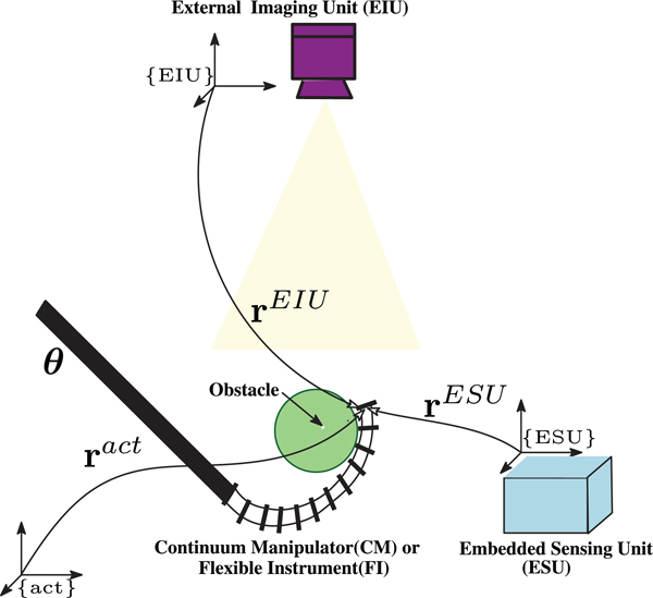
As shown in Fig. 2, similar to various surgical robotic interventions, we consider a robotic system comprising a CM/FI with unknown deformation model equipped with two sensing units: 1) an ESU with high-frequency and low-accuracy measurements and 2) an EIU with low-frequency and high-accuracy outputs. The goal is to fuse the outputs of these sensing units for 1) online estimation of the CM/FI deformation model and 2) an accurate high-frequency estimation of CM/FI tip position. It is worthwhile to emphasize that obtaining a prior CM/FI’s deformation model is not feasible in real-world medical applications due to its potential alteration during interaction with unknown obstructed environments. With these objectives in mind, we make the following assumptions/remarks.
Fig. 2.
Conceptual illustration of the SCADE algorithm for position estimation of a CM/FI working in an obstructed environment. In the SCADE, using an EIU providing intermittent external position feedback and an ESU (e.g., FBG or magnetic sensors) with continuous feedback, a priori model-independent sensor fusion algorithm is used to simultaneously recalibrate the ESU and estimate the deformation behavior of the CM/FI. In this figure, represent the position of the CM/FI’s tip position with respect to a Cartesian space {act}, embedded sensing unit {ESU}, and external imaging unit {EIU} frames, respectively. Also, denotes the vector of actuation inputs of the CM/FI.
Remark 1:
In this article, we use FBG sensors as the ESU and a camera as the EIU. However, other types of embedding sensing units (e.g., magnetic or piezoelectric sensor) and external imaging modalities (e.g., MRI, X-ray, or ultrasound) are also applicable.
Remark 2:
In this article, in order to fuse the FBG and camera data, we introduce an mi-KF approach. This method unlike the common filtering approaches does not require a priori state transition matrix (i.e., description of nominal expected deformation behavior of the CM/FI state variables). Instead, we estimate this matrix in real time and use it for recalibration of the FBG sensors.
Remark 3:
We assume the FBG sensors were calibrated offline; however, this calibration can dynamically change during bending motion of the CM/FI or interaction with an unknown environment. For CM/FI calibration and model-based shape reconstruction, we use inaccurate shape reconstruction and 2-D–3-D registration methods presented in [21] and [18], respectively. Hence, considering Remark 2, the main focus of this article is fusing these data in order to improve the accuracy of the FBG sensor shape reconstruction with an intermittent/low frequency use of an external imaging source.
Remark 4:
The word “dynamics” used throughout the article refers to the “time evolution of the system states in KF.” We also used the term “deformation behavior” to indicate the unknown and unmodeled dynamics of a CM, which we formulated/linearized it using a “kinematic deformation Jacobian.”
B. CM/FI’s a Priori Model-Independent Deformation Formulation
As shown in Fig. 2, consider represents the tip position of the CM/FI in Cartesian space, and denotes the vector of actuation inputs of the CM/FI
| (1) |
Now, assume there is a smooth unknown nonlinear function expressing the deformation behavior of the CM/FI as a function of the actuation inputs in each time instant
| (2) |
Since is unknown, at each time instant i, we can estimate it using the following first-order linear model:
| (3) |
where and and is the Jacobian of the CM/FI deformation behavior in each time instant i and is the value of its (p, q) element.
This linear model is locally valid around the vector of actuation inputs at time instant is negligible) and therefore we can rewrite (2) as
| (4) |
where and
Considering (4), we can formulate this problem as the following linear stochastic difference equation:
| (5) |
where is an independent additive white noise with zero mean and covariance of capturing the uncertainty in the dynamics model, and for the ease of notation, represents
In (5), we are looking for a real-time a priori model-independent method to estimate the deformation Jacobian given the change in the vector of actuation inputs and displacements of the CM/IF tip position
C. mi-KF for Estimation of the Deformation Jacobian Matrix
The common discrete KF addresses the general problem of estimating a state vectors of a discrete-time controlled process defined by the following linear stochastic difference equation:
| (6) |
where is the state at time is an input control vector, is additive process noise, is the input transition matrix, and is the state transition matrix.
In addition, the observation of the states or measurements is represented by the following linear equation:
| (7) |
where is the observation matrix and is additive measurement noise [37].
In these equations, the goal is to estimate the state vector si, given known matrices of and and Hi, inputs of ui, zi, and statistics of wi, νi. In this formulation, the process noise wi and measurement noise νi are random vectors assumed to be uncorrelated, zero mean with normal probability distributions and known covariance matrices and respectively. Also, the initial system state s0 is a random vector that is uncorrelated with both the process and measurement noise, and has a known mean and covariance matrix.
As we mentioned in Remark 2, unlike the common use of a KF in estimation of a vector (i.e., state vectors), in this article, we introduce a novel mathematical formulation to simultaneously estimate a matrix (i.e., the state transition matrix ) along with a vector (i.e., the state vector s) in real time. Of note, estimating the state transition matrix in real time, which indeed defines the CM/FI’s deformation behavior, is the main reason that enables our framework to be generic and implemented on various types of flexible robots/instruments. To this end, we first define the following operators.
1). Stack Operator [38]:
The stack operator maps a p × q matrix in to a pq × 1 vector. The stack of the p × q matrix denoted by is the vector formed by stacking the q columns of on top of each other to form a pq × 1 column vector. For instance, if is a p × q matrix comprising q column vectors where each is a p × 1 vector, i.e.,
then
Remark 5:
The stack operator maps a column vector to itself (i.e., when ), whereas it maps a row vector to its transpose (i.e., when ).
2). Kronecker Product [38]:
The Kronecker product is a binary matrix operator that maps two arbitrarily dimensioned matrices into a larger matrix with special block structure. Given and , the Kronecker product of these matrices, denoted by is an rp × sq matrix with the following block structure:
where is the ijth element of matrix
Considering the defined operators, it can be easily proved that the stack of a matrix multiplication, given the dimensions are appropriate for the product to be well defined, is [38]
| (8) |
Using (8) and Remark 5, for the following special case, when dimensions are appropriate for a general matrix–vector multiplication we can write
| (9) |
where an m × m identity matrix.
Remark 6:
From now on, we denote an identity matrix with dimension as Iα and a zero matrix with dimension as
Comparing (5) with (9) and applying the stack operator on both sides of (5), we can express this time difference equation at time instant i as
| (10) |
In (10), thanks to the implemented mathematical operations, unknown position vector and the stacked deformation Jacobin vector are linearly dependent. This enables us to stack these two vectors and simultaneously estimate them using KF formulation. The following sections describe the mathematical details of this procedure.
D. Sensor Fusion for Simultaneous Sensor Calibration and CM/FI Deformation Estimation (SCADE)
The goal here is to introduce a method for estimating unknown position vector and the stacked deformation Jacobin vector when continuous measurements from the ESU and intermittent feedback from the EIU are available.
As mentioned in Remark 4, we assume that the embedded sensor was calibrated offline but this calibration may vary due to the bending motion of the CM/FI or its interaction with the environment. In this section, we derive the necessary equations for fusing the streamed sensing data of both ESU and EIU in the SCADE framework. The main idea here is that the data from a high speed but low-accuracy ESU (e.g., FBG or magnetic tracker) are used as a backbone providing real-time inaccurate position estimation of the CM/FI end-effector/tip. Whenever the low speed/intermittent but high-accuracy EIU (e.g., camera or X-ray) provides an accurate position update, the difference between the position estimated from the two sources is used to improve the robot’s deformation model as well as the position estimation.
1). ESU Signal Modeling:
As mentioned in Remark 4, the ESU calibration is not accurate and is vulnerable to alteration during interaction of the CM/FI with the environment [16]. To capture this unknown time-varying alteration/bias, we model the position estimation signal provided by the ESU, at each time instant i using the following stochastic difference equation:
| (11) |
where is the unknown and time-varying bias in the calibrated ESU representing the alteration between the calibration results and the real position vector . The denotes the ESU noise vector assumed to be additive white noise with zero mean and covariance of and independent from
Considering (11), we model the slowly changing dynamics of the ESU bias as a random walk process [37] with Gaussian steps
| (12) |
where is assumed to be an additive white noise with zero mean and covariance of
Likewise, the slowly changing deformation Jacobian of the CM/FI can be modeled by the following stochastic difference equation:
| (13) |
where and denote the stacked deformation Jacobian at time i and i − 1, respectively. Also, is a general unknown and time-varying evolution term describing the dynamic change of the CM/FI Jacobian. is assumed to be additive white noise with zero mean and covariance of
We also assume that the slowly changing dynamics of the CM/FI Jacobian follows a Gaussian random process
| (14) |
where assumed to be additive white noise with zero mean and covariance of
2). EIU Signal Modeling:
We assume that the EIU measurements of the CM/FI position have adequate accuracy and can be obtained by proper image processing and registration methods. Considering this assumption, the deployed model to represent the EIU signal is as follows:
| (15) |
where is the position estimations from the EIU at time instant j deteriorated by vector denoting the EIU noise vector. This noise vector is assumed to be additive white noise with a priori statistics of zero mean and covariance of and independent from
Note that time indices in (11) and (15) are denoted differently (i.e., i versus j), emphasizing different sampling frequency for the ESU and EIU.
3). Derivation of Dynamics Model:
We formulate the time difference dynamic equation by calculating the difference between the predicted position in (10) at time instant i and the ESU measurement (11) in time instant i − 1 to obtain
| (16) |
where is the CM/FI displacement obtained from the ESU position measurement at time i − 1 to the actual position at time i.
This formulation allows us to provide a modified dynamics equation with the coupled position error, the ESU bias, the stacked deformation Jacobian, and the evolution term in Jacobian as our new augmented states vector x
| (17) |
where
Now, considering (14)–(17), the dynamics equation describing the evolution of the augmented states can be formulated as
| (18) |
where and are defined as follows:
| (19) |
The measurement noise of the ESU the process noise in the dynamics model the random walk process noise the noise signal in the estimated Jacobian deformation and the noise signal in the CM/FI Jacobian evolution term are all assumed to be uncorrelated discrete-time white noise signals. Hence, the vector is an additive white noise with zero mean and covariance of
| (20) |
where Diag(·) denotes a block diagonal matrix.
4). Derivation of Measurement Model:
Considering the defined displacement state and to construct a proper measurement model for the SCADE algorithm, we constitute a measurement model by subtracting the position data obtained by EIU at time j from the position information obtained from ESU at time j − 1
| (21) |
where is directly obtained from the information of the two sensing units. The noise vector vj is assumed to be an additive white noise with zero mean and covariance of Note that we assume the returned data by the EIU is reasonably accurate and comparable to the true value of the CM/FI position Hence, considering (7), the state-space model of the measurement can be obtained from the following equation:
| (22) |
where and are defined as follows:
5). SCADE Algorithm:
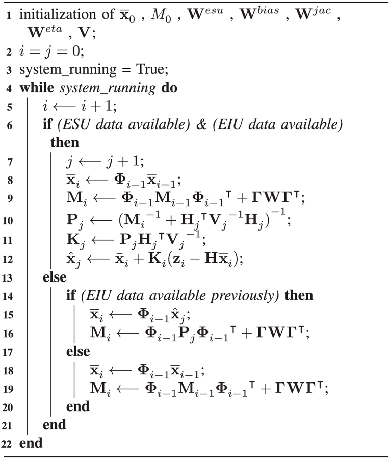
Equations (18) and (22) provide the state-space dynamics and measurement models of our system. Considering the different measurement frequencies of the ESU and EIU, we perform the estimation in two separate phases: 1) when only the ESU data are available (i.e., Phase I), and 2) when both ESU and EIU data are available (i.e., Phase II). Note that at a given time, the system is either in Phase I or Phase II. The following describes the iterative mi-KF estimation of states and error covariances in each phase.
In Phase I, when only the ESU data are available, the best estimate of state and a priori covariance matrix is propagated based on the following difference equations:
| (23) |
where and are obtained from (19) and (20).
In Phase II, when both ESU and EIU data are available, the best estimate of state and a posteriori covariance matrix is obtained from the following
Algorithm1:
The SCADE Algorithm
 |
relations:
| (24) |
where is called the Kalman gain and denotes the most recent increment in Phase I (i.e., and are all the most recent updates calculated in Phase I).
For the next time step of the dynamics, when the system is again in Phase I (i.e., only the ESU data is available), the best estimate of state and a priori covariance matrix M is calculated as follows:
| (25) |
From this time onward, (23) is used to propagate the state and covariance matrix until the system returns to Phase II and this iterative loop continues. Algorithm 1 summarizes the mentioned SCADE algorithm. Note that in this algorithm, we have dropped the time indices for the quantities that are time invariant. Moreover, M0, as the initial a priori error covariance matrix, is selected based on the combination of empirical estimations and preliminary experiments performed on the system [37]. The uncertainty variables are selected to minimize the uncertainty in the tip estimations using the SCADE algorithm.
III. Experimental Setup
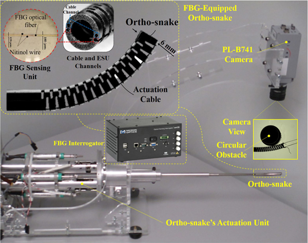
The experimental setup used for the evaluation of SCADE was also previously reported in [23]. As shown in Fig. 3, the experimental setup consists of a CM equipped with two embedded FBG shape sensors (as the ESU), the CM’s actuation unit, an FBG interrogator, an overhead camera (as the EIU) and a custom C++ software to control the CM and collect data from the shape sensors and the camera. The following briefly describes each module and its preparation before each experiment.
Fig. 3.
Experimental setup including the ortho-snake with lateral notches providing planar bend for the CM and equipped with embedded FBG shape sensors (as the ESU), the ortho-snake’s actuation unit, FBG interrogator, and an overhead camera (as the EIU) [23].
A. Ortho-Snake and Its Actuation Unit
The CM used for performing the experiments is a cable-driven CM, called “ortho-snake,” which has been specifically designed for orthopedic applications [36]. This CM has an outer diameter of 6 mm and a tool channel of 4 mm, and is fabricated from two nested pieces of superelastic Nitinol tubes. Post machining using a wire electrical discharge machining (EDM) creates the peripheral notches of the ortho-snake with 35 mm length enabling it to bend large curvatures up to 166.7 m−1 [39]. As shown in Fig. 3, there are four small channels with 0.6 mm diameter in the walls of ortho-snake; two of them are used for passing cables for bending control of this CM in a plane These cables are actuated antagonistically with an actuation unit consisting of two dc motors (RE10, Maxon Motor, Inc., Switzerland) with spindle drives (GP 10 A, Maxon Motor, Inc., Switzerland). A commercial controller is used to power and connect individual Maxon controllers (EPOS 2, Maxon Motor, Inc., Switzerland) on a controller area network (CAN bus). Using libraries provided by Maxon, a custom C++ interface communicates over a single universal serial bus (USB) cable and performs position control of the motors.
B. FBG Sensing Unit
To obtain the shape of ortho-snake during its actuation, two FBG shape sensing units embedded in ortho-snake’s wall channels, was used as shown in Fig. 3. Each unit includes a fiber array (100 μm diameter) with three FBG sensing areas (Technica Optical Components, China) distributed 10 mm apart, which has been UV-glued (Henkel, Germany) to two 125 μm Nitinol wires (NDC Technologies, USA). The detailed design and fabrication of this sensor assembly and its fabrication procedure can be found in [17] and [21]. To estimate and reconstruct the shape of ortho-snake using the FBG sensing unit, a two-step process was utilized [21]: 1) an offline curvature calibration for ortho-snake’s C-shaped bending motions, and 2) a model-based shape-reconstruction procedure developed based on a linear curvature assumption between each sensing node of the sensing assembly.
For an FBG optical sensor, the equation relating the wavelength shift Δλ of each sensing areas to their corresponding strain s can be calculated as
| (26) |
where ΔT is the temperature change, is the strain coefficient, and cT is the temperature coefficient.
Considering (26) and assuming negligible temperature variation (ΔT ≈ 0), we used a dynamic optical sensing interrogator (Micron Optics sm130, Micron Optics, Inc., USA) and performed an offline calibration procedure to map wavelength shift to the curvature κ of the ortho-snake during its C-shaped bending motions
where relates the wavelength shift at the three sensing areas of each FBG sensor to the corresponding curvature values at these three points. The details of the calibration procedure can be found in [17].
To reconstruct the shape of ortho-snake using the calibration mapping function ψ for each shape sensor, we first assumed a linear relationship between the calibrated discrete curvatures and arc length L of each sensor and divided the sensor length to n sufficiently small segments. Using the interpolated curvature at each segment (κl for l = 1,...,n), the curvature angle of each segment was calculated as follows:
The 2-D shape of each sensor can be then reconstructed sequentially using the following formulations:
The tip position of the ortho-snake along its center line is then calculated by averaging the position values for the shape sensors, which we refer to as at each time instant i.
This model-based shape-reconstruction procedure often results in a poor and inaccurate position estimation in real-world application, where the CM may undergo large deflections or collide with the obstructed environment in a non-quasi-static motion [21], [23]. This is mainly due to a manual fabrication procedure, an offline static C-shaped calibration procedure based on limited and discrete wavelength shift readings and the linear interpolation assumption made during the shape reconstruction procedure [39].
C. External Imaging System
In the experiments, we simulated an intermittent external imaging system with an overhead PL-B741 camera (PixeLink, USA) mounted above the ortho-snake. The camera was mounted such that its focal plane was parallel with the bending plane of the CM. A 2-D–3-D registration method [18] was used on the taken intermittent images to compute the ortho-snake’s outline and its shape curve in each image. In summary, using the cameras intrinsic and extrinsic parameters, the 3-D model and joint configuration of the CM, this registration algorithm fits a cubic spline with five control points to estimate the shape of the CM. This 2-D–3-D registration method approximates the ortho-snakes tip position with an error less than 0.4 mm. We refer to the output of this registration procedure as at each time instant i.
D. Setup Preparation
Before conducting the experiments, a manual calibration was performed to define the zero cable position for both cables and avoid any slack in the ortho-snake’s actuation mechanism. The camera was then calibrated using a standard square chessboard and obtained the intrinsic parameters. In the performed experiments, FBG data were streamed by an optical sensing interrogator at 15 Hz, whereas the camera images were collected at 0.5 Hz, obligated by the hardware and software limitations. It is worth noting that due to the 2-D bending nature of the utilized CM (i.e., M = 2) and using two cables for bending control of the CM (i.e., N = 2), the developed generic relations in Section II have the following reduced dimensions: and
IV. Experimental Results
The data from two sets of previous experiments [23] was used to evaluate the effectiveness of our model-independent SCADE algorithm. The experiments included deformation and shape estimation in 1) a free bending motion without the presence of an obstacle in the environment and 2) a bending motion in an obstructed environment. Of note, in both experiments, the ortho-snake’s cables were antagonistically actuated at different cable displacement rates. As reported in [16] and [23], due to an offline static calibration of the FBG sensing units, a dynamic actuation and obstacle collision in an unknown environment might change the calibration parameters resulting in an inaccurate tip position estimation.
Additionally, as we discussed in Section I, the main clinical motivation of the SCADE algorithm was to reduce the radiation exposure of a fluoroscopy machine by taking minimum number of X-ray images in various interventional radiology and orthopedics procedures (e.g., [36]). To this end, we fused high-frequency data of the ESU with low-frequency EIU images within the SCADE framework. This enables to 1) mitigate the safety concerns of using fluoroscopy machines and 2) improve the estimation of the CM/FI position as compared to using the ESU data only. To study the effect of the EIU imaging frequency on the performance of the SCADE algorithm, we performed an experiment and analyzed the results.
A. Free Bending
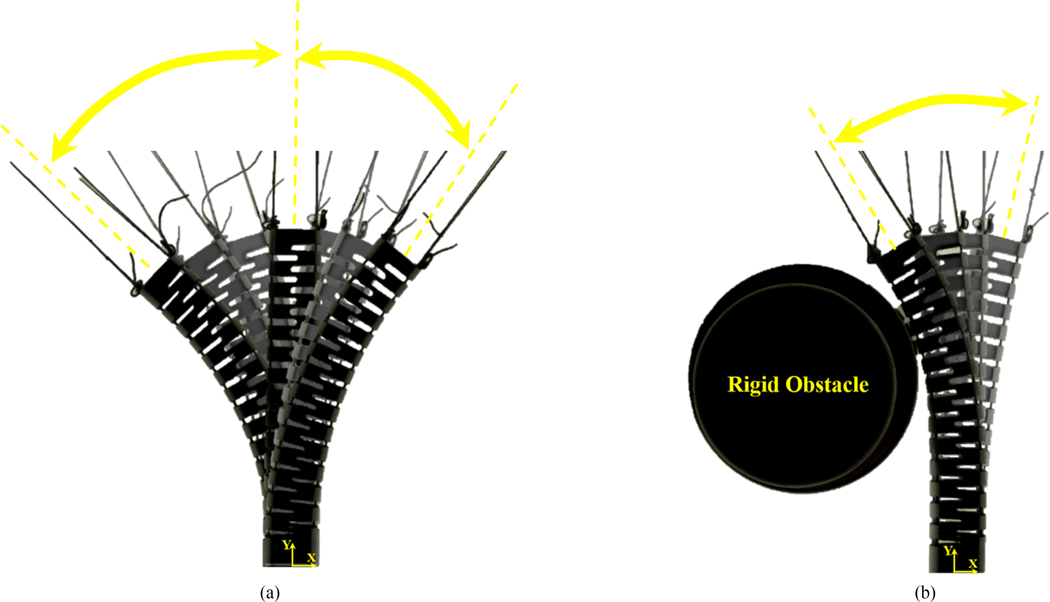
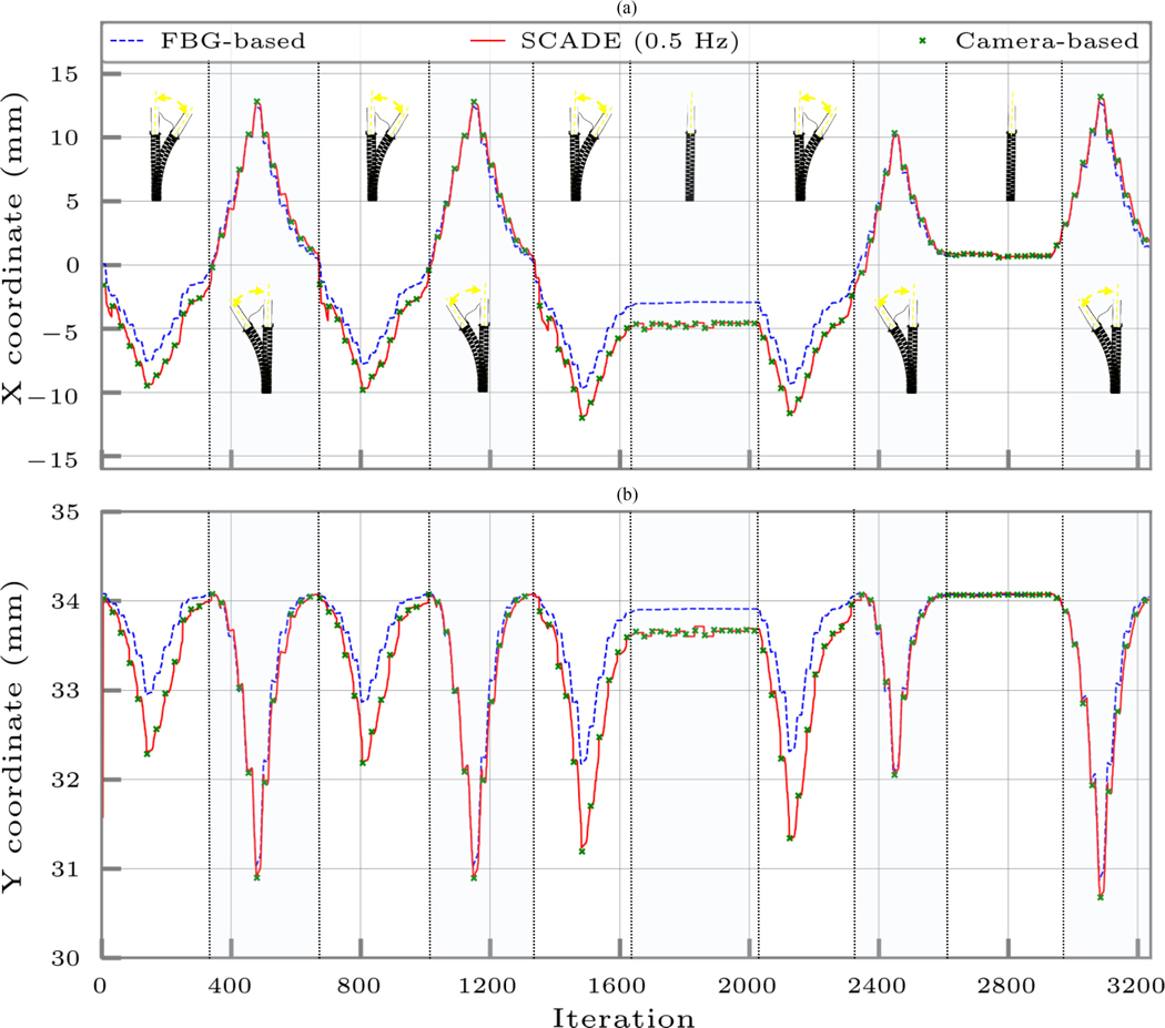
As shown in Fig. 4(a), in this set of experiments, the ortho-snake’s cables were antagonistically actuated with continuous displacement rates of 0.5 and 1 mm/s in a free environment with no obstacle. It is worth noting that these displacement rates are clinically viable values, which are obtained experimentally for minimally invasive treatment of hard lesions by ortho-snake [32], [35]. To ensure repeatability, each experiment included various cycles of free bends with the maximum cable displacement of 3 mm, short stays at this bending configuration to study the effect of calibration bias and hysteresis on the position estimations, and subsequently returns to the initial straight position. This scenario was also repeated in the opposite bending direction.
Fig. 4.
(a) Snapshots of the ortho-snake’s bending motion in the free-environment experiments taken by the overhead camera. To ensure repeatability, each experiment included various cycles of bending in one direction, short stay at the bending configuration, and subsequently a return to the initial straight position. This scenario is also repeated in the opposite bending direction. (b) Snapshots of the ortho-snake’s bending motion in the obstructed environment experiments taken by the overhead camera. To ensure repeatability, each experiment included various cycles of bending and colliding with the obstacle [23].
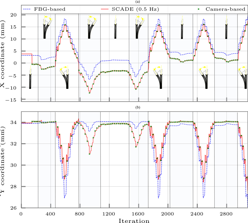
Figs. 5 and 6 demonstrate the results of the experiments performed with 0.5 and 1 mm/s cable displacement rates, respectively. These figures demonstrate the ortho-snake’s estimated tip position (i.e., the X and Y coordinates) using the following:
-
1)
only the streamed FBG data and the model-based reconstruction method described in Section III-B;
-
2)
the instances of recorded and registered images by the camera;
-
3)
our proposed model-independent sensor fusion algorithm (i.e., the SCADE algorithm).
Fig. 5.
Ortho-snake’s estimated tip position (i.e., the X and Y coordinates) when its cables were antagonistically actuated with continuous displacement rates of 0.5 mm/s in the free environment and without the presence of obstacles using 1) only the streamed FBG data and the online model-based reconstruction method described in Section III-B, 2) the instances of recorded and registered images by the camera with frequency of 0.5 Hz, and 3) the SCADE algorithm. The bending configurations of the CM have been shown in each cycle. The tip position is considered at the distal end point of the center line of the robot.
Fig. 6.
Ortho-snake’s estimated tip position (i.e., the X and Y coordinates) when its cables were antagonistically actuated with continuous displacement rates of 1 mm/s in the free environment and without the presence of obstacles using 1) only the streamed FBG data and the online model-based reconstruction method described in Section III-B, 2) the instances of recorded and registered images by the camera with frequency of 0.5 Hz, and 3) the SCADE algorithm. The bending configurations of the CM have been shown in each cycle. The tip position is considered at the distal end point of the center line of the robot.
To better represent the bending configurations of the ortho-snake and repeatability of the SCADE’s results, various bending cycles of the experiment are shown in these figures.
B. Bending in an Obstructed Environment
For these experiments, the ortho-snake’s cables were antagonistically actuated with continuous displacement rates of 0.5 and 1 mm/s for a maximum cable displacement of 2 mm. Fig. 4(b) demonstrates snapshots of this set of experiments, taken by the overhead camera, when the ortho-snake collides with a rigid circular obstacle with 25 mm diameter during its bending motion. Similar to the previous free-bending experiments, to ensure repeatability of the results, these experiments included various cycles of bending motions in the presence of the obstacle and returning to the straight configuration.
Figs. 7 and 8 demonstrate the results of these experiments performed with continuous displacement rates of 0.5 and 1 mm/s, respectively. Similar to the free-bending experiments, these figures represent the ortho-snake’s estimated tip positions (i.e., the X and Y coordinates) using the following:
-
1)
only the streamed FBG data and the online model-based reconstruction method described in Section III-B;
-
2)
the instances of recorded and registered images by the camera at 0.5 Hz frequency;
-
3)
our proposed model-independent sensor fusion SCADE algorithm.
Fig. 7.
Ortho-snake’s estimated tip position (i.e., the X and Y coordinates) when its cables were antagonistically actuated with continuous displacement rates of 0.5 mm/s in the obstructed environment using 1) only the streamed FBG data and the online model-based reconstruction method described in Section III-B, 2) the instances of recorded and registered images by the camera with frequency of 0.5 Hz, and 3) the SCADE algorithm. The bending configurations of the CM have been shown in each cycle. The tip position is considered at the distal end point of the center line of the robot.
Fig. 8.
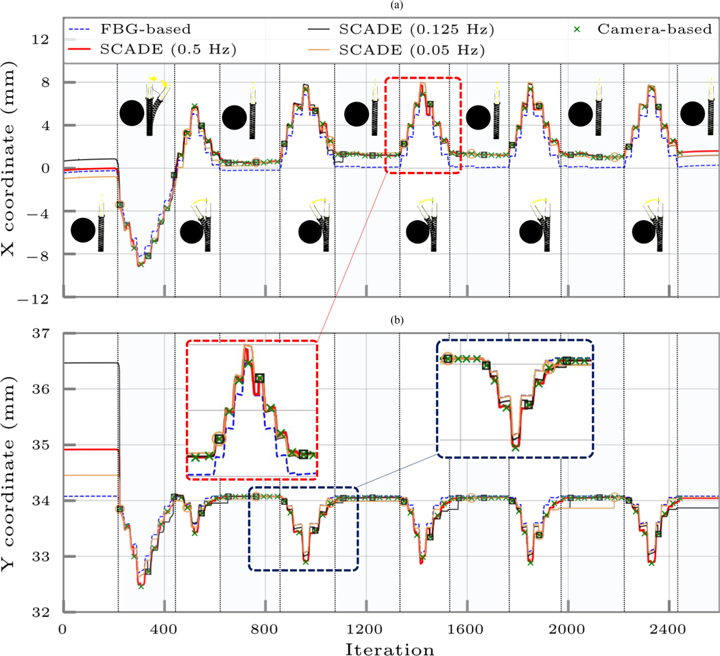
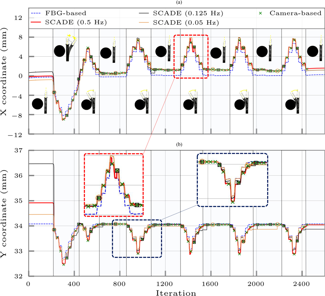
Ortho-snake’s estimated tip position (i.e., the X and Y coordinates) when its cables were antagonistically actuated with continuous displacement rates of 1 mm/s in an obstructed environment using 1) only the streamed FBG data and the online model-based reconstruction method described in Section III-B, 2) the instances of recorded and registered images by the camera, and 3) the SCADE algorithm performed with three different EIU imaging frequencies of 0.5, 0.125, and 0.05 Hz. The bending configurations of the CM have been shown in each cycle. The tip position is considered at the distal end point of the center line of the robot.
These figures also show different bending cycles of these experiments to better represent the bending configurations of the ortho-snake and repeatability of the SCADE’s estimation results.
C. Effect of the EIU Imaging Frequency on the SCADE Performance
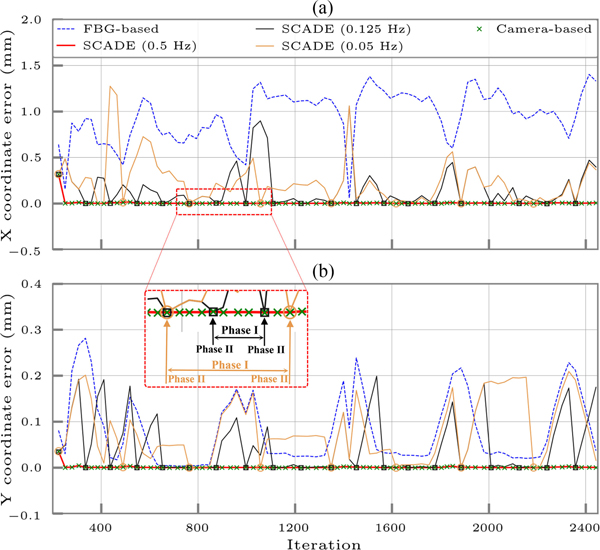
In this experiment, we studied ten decreasing frequencies from 0.5 (i.e., every 2 s) to 0.05 Hz (i.e., every 20 s) representing a wide range of the rate of images obtained by the EIU during the procedure. We performed our analysis when the ortho-snake was bending in the obstructed environment with 1.0 mm/s displacement rate and the FBG reading rate was identical to all other experiments (i.e., 15 Hz). Fig. 8 and Table II summarize the results of this experiment. Of note, only three representative frequencies of 0.5, 0.125, and 0.05 Hz have been shown in Fig. 8 for brevity and better representation of data.
TABLE II.
Effects of the EIU Imaging Frequency on the MTPE
| MTPE in X coord. (mm) | MTPE in Y coord. (mm) | MTPE (mm) | |
|---|---|---|---|
| SCADE (0.5Hz) | 0.007 ± 0.035 | 0.001 ± 0.004 | 0.001 ± 0.001 |
| SCADE (0.125Hz) | 0.160 ± 0.216 | 0.047 ± 0.062 | 0.165 ± 0.203 |
| SCADE (0.05Hz) | 0.231 ± 0.251 | 0.078 ± 0.066 | 0.255 ± 0.247 |
| FBG-based | 0.953 ± 0.275 | 0.082 ± 0.075 | 0.961 ± 0.271 |
These results have been calculated for a bending motion in an obstructed environment with continuous displacement rate of 1 mm/s.
V. Discussion
To evaluate the performance of the SCADE algorithm, we used data of an FBG-equipped CM. As discussed throughout the article, the overall performance of an FBG sensing unit depends on four main attributes. First, the fabrication of the FBG sensor assembly, which is very difficult due to the size and delicacy of the FBG optical sensors, and highly depends on the user’s expertise [22]. Second, the locations and numbers of sensing nodes, which are application specific with no generic standard to define these parameters [40], [41]. Although using more sensing nodes can increase the estimation accuracy, it in return increases the fabrication costs [16]. Third, the shape reconstruction procedure, which is typically performed using a model-based approach [16], [17]. For instance, assumptions such as a linear relationship between the sensing nodes of a sensing unit [21] that typically used in the shape reconstruction procedure directly affect the results of shape/tip estimation [25]. Fourth, the CM’s contact with the environment, which might result in a time-varying and hard-to-model bias [23]. Investigation of Figs. 5 and 6 clearly demonstrates the inferior results of solely using the FBG sensing unit and a model-based approach in estimation of the ortho-snake’s tip position (i.e., X and Y coordinates) compared to the ground truth value obtained by the EIU. As summarized in Table I, the obtained results for free-bending experiments show mean tip position error (MTPE), i.e., the absolute error between the ground truth and the FBG-based estimation of 1.0895 ± 0.780 and 3.421 ± 1.077 mm for the 0.5 and 1 mm/s cable displacement rates, respectively. For the experiments performed in the obstructed environment and shown in Figs. 7 and 8, an MTPE of 2.719 ± 0.839 and 0.961 ± 0.271 were calculated for the FBG-based estimations with 0.5 and 1 mm/s cable displacement rates, respectively. These analyses clearly demonstrate the sensitivity of the FBG-based estimations (i.e., calibration parameters of the ESU) to the change in the experimental conditions (i.e., the displacement rates and bending cycles) even in an identical obstructed/free environment. As described, the main attributes of this estimation error for both set of experiments are the manual fabrication of the FBG sensing unit, static calibration, as well as the hysteresis due to the friction between the ESU and the CM channels [21], [39].
TABLE I.
Calculated MTPE in the Performed Experiments With the EIU Imaging Frequency of 0.5 Hz
| MTPE in X coord. (mm) | MTPE in Y coord. (mm) | MTPE (mm) | ||||
|---|---|---|---|---|---|---|
| SCADE | FBG-based | SCADE | FBG-based | SCADE | FBG-based | |
| Obstructed (1 mm/s) | 0.007 ± 0.035 | 0.953 ± 0.275 | 0.001 ± 0.004 | 0.082 ± 0.075 | 0.001 ± 0.001 | 0.961 ± 0.271 |
| Obstructed (0.5 mm/s) | 0.012 ± 0.009 | 2.691 ± 0.864 | 0.011 ± 0.008 | 0.283 ± 0.184 | 0.017 ± 0.010 | 2.719 ± 0.839 |
| Free Bending (1 mm/s) | 0.010 ± 0.007 | 3.310 ± 1.117 | 0.011 ± 0.009 | 0.620 ± 0.529 | 0.016 ± 0.009 | 3.421 ± 1.077 |
| Free Bending (0.5 mm/s) | 0.010 ± 0.008 | 1.062 ± 0.750 | 0.010 ± 0.007 | 0.217 ± 0.231 | 0.016 ± 0.009 | 1.089 ± 0.780 |
In contrast to the results obtained by merely using the FBG, as observed in all four experiments, the proposed sensor fusion algorithm could substantially improve the CM deformation and subsequently tip position estimation without utilizing a priori deformation model of the ortho-snake. The fusion of the streamed FBG data with the intermittent low-frequency EIU not only may eliminate the tip position estimation errors by using solely the ESU data but it can also capture the dynamic offset between the ESU and EIU when the EIU data are not available. As summarized in Table I, the MTPE of 0.016 ± 0.009 mm between the camera and the SCADE algorithm was obtained in both free-bending experiments. For the experiments performed in the obstructed environment, these errors were 0.017 ± 0.010 and 0.001 ± 0.001 mm for the 0.5 and 1 mm/s cable displacement rates, respectively. This is mainly due to the described two-phase sensor fusion algorithm, which simultaneously estimates the unknown deformation behavior of the CM and calibrates the unknown bias of the FBG sensing unit on the fly. Additionally, investigation of the initial iterations of all four experiments clearly reveals the appropriate and punctual performance of the SCADE algorithm. This is mainly because the SCADE algorithm suddenly improves the tip position estimation once EIU data are available and are fused with the FBG data. Similarly, this sudden drop/overshoot in the estimation error is also observed through the experiments where a transition between Phases I [i.e., propagation based on (23)] and II [i.e., a sensor fusion based on (24)] of the SCADE algorithm occurs.
Analysis of Fig. 8 shows the effect of the EIU imaging frequency on the SCADE performance. First, as can be observed, the SCADE algorithm outperforms the FBG-based estimations for all considered EIU frequencies. As summarized in Table II, the MTPE of the lowest imaging frequency (i.e., 0.05 Hz) is 0.255 ± 0.247 mm, which is still approximately four times better than the FBG-based estimation with MTPE of 0.961 ± 0.271 mm. Second, as expected, by reducing the imaging frequency to ten times slower rates, the estimation error increases from 0.001 ± 0.001 mm for the 0.5 Hz (i.e., the highest frequency) to 0.255 ± 0.247 mm for the lowest considered frequency. Of note, although this feature may compromise the estimation accuracy, from the clinical aspect it can result in a safe and low radiation exposure in fluoroscopic procedures. Third, a similar pattern to the other experiments for the estimation tip position and error is observed. This pattern is referred to the transition from Phases I to II of the SCADE algorithm at the beginning and through the experiments, which proves the robust performance of the proposed algorithm.
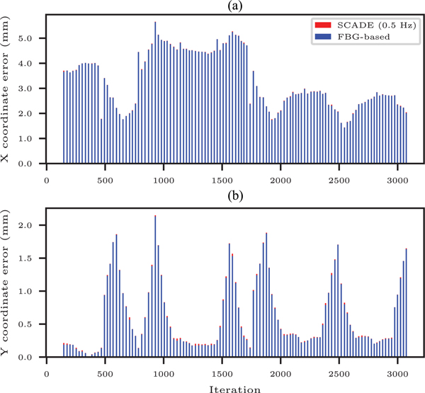
Fig. 9 shows the stacked FBG-based and SCADE-based position estimation errors during bending motion in free environment with 1 mm/s cable displacement rate. This error was calculated at instances when the ground truth data were available from the EIU with frequency of 0.5 Hz (i.e., Phase II of the SCADE algorithm). As observed in this figure, the estimated positions in both X and Y coordinates using only FBG sensing unit are much larger than the ones obtained from the SCADE algorithm. The absolute estimation error in the X coordinate is 3.310 ± 1.117 mm, which is one order of magnitude larger than 0.620 ± 0.529 mm error associated with the Y coordinate. The relative error of estimations along the X and Y coordinates was calculated as 10.73% and 8.72% of the range of motion along these axes, respectively. These errors might be due to the poor manual fabrication procedure and/or heterogeneous friction or hysteresis distribution along the FBG sensing unit and the ortho-snake channels. However, as can be seen in Table I, these adverse effects and errors have been eliminated by the deployed model-independent sensor fusion algorithm.
Fig. 9.
Stacked FBG-based and SCADE-based absolute position estimation errors during free-bending experiments with continuous displacement rate of 1 mm/s. The errors have been calculated at iterations when the ground truth data are available from the EIU (with frequency of 0.5 Hz (i.e., Phase II of the SCADE algorithm).
Fig. 10 shows the corresponding FBG-based and SCADE-based position estimation errors of the results presented in Fig. 8. To calculate these errors, the obtained positions by the highest frequency rate of the EIU (i.e., every 2 s) were considered as the ground truth. We then calculated the corresponding absolute estimation errors of the FBG and the SCADE algorithms at various imaging frequencies and identical instances with respect to this ground truth. It is worth noting that the stacked estimation errors demonstrated in Fig. 9 were only calculated at Phase II of the SCADE algorithm. However, the presented errors in Fig. 10 show the error of estimations in both Phases I and II of the SCADE algorithm and obtained based on different imaging frequencies (i.e., 0.5, 0.125, and 0.05 Hz). To emphasize, Phase I refers to the estimations solely obtained by the state transition matrix, whereas Phase II refers to the estimations calculated based on the state transition matrix and camera images. The magnified region in Fig. 10 shows the instances when the MTPE error has been calculated based on Phase I or Phase II of the SCADE algorithm in each imaging frequency. As can be observed in this figure and summarized in Table II, similar to the results shown in Fig. 9, the estimated positions in both X and Y coordinates using only FBG sensing unit are much larger than the ones obtained from the SCADE algorithm with different frequencies. Complementary to the results obtained from Fig. 10, analysis of Table II and Fig. 10 conveys that the estimation accuracy of the SCADE algorithm decreases with reducing the frequency of imaging by the EIU. Quantitatively, according to Table II, the MTPE of the estimated positions increases from 0.001 ± 0.001 to 0.255 ± 0.529247 mm by making the imaging frequency ten times slower. Nevertheless, the MTPE of the SCADE at lowest imaging frequency is still approximately four times less than the FBG-based estimations. Further, Fig. 10 clearly shows the significance and capability of the SCADE algorithm in reducing the MTPE when the EIU and ESU data are fused. These instances can be distinguished by different markers in Fig. 10, when the MTPE of all frequencies suddenly drops due to the sensor fusion.
Fig. 10.
Comparison of absolute estimation errors performed by the FBG-based and SCADE-based methods during bending in an obstructed environment with continuous displacement rate of 1 mm/s. The SCADE-based estimations have been performed in three different frequencies (i.e., 0.5, 0.125, and 0.05 Hz). The absolute errors have been calculated at iterations when the ground truth data are available from the EIU. The magnified region shows the instances when the error has been calculated based on Phase I or Phase II of the SCADE algorithm for the corresponding imaging frequency.
The presented experimental results also demonstrate the capability and performance of the SCADE algorithm in capturing the deformation behavior of a CM without having a prior knowledge about its deformation behavior. It is worth emphasizing that other sensor fusion methods in the literature (e.g., [24], [26], and [27]) require a known kinematics or dynamics model of the CM/FI, which makes their usage very limited to a particular type of robot. In addition, most of these models have been derived or experimentally tuned for a specific experimental condition and often are not generic. One of the main advantages of the presented model-independent approach, however, is its independence to the experimental condition together with its expandability to different type of CMs/FIs. As presented in Figs. 5–7, the SCADE can successfully estimate the deformation behavior of the ortho-snake both in the free-bending and obstructed environments.
To address the mentioned limitations of the FBG-based shape/position estimation of CMs/FIs and with the goal of increasing the resolution of curvature estimation along the CM/FI length, a group of researchers (e.g., [40]–[42]) has proposed the use of more shape sensing units or sensing areas on each shape sensing unit [16]. Although this approach may potentially improve the estimation accuracy, it dramatically increases the cost of fabrication of each sensing unit. Another advantage of our proposed sensor fusion method, however, is its potential to improve the estimation accuracy with minimum number of sensing areas and subsequently lower fabrication costs when fused with another external imaging modality. As described, there exist various surgical interventions (e.g., breast and brain biopsy, and orthopedic surgeries) that already using an external imaging modality during a surgical procedure. Hence, these devices can potentially be utilized as an EIU within the SCADE framework.
VI. Conclusion
In this article, we presented a model-independent sensor fusion framework based on a novel mathematical formulation. This framework enables us to estimate a linearized state transition matrix, which represented the unknown deformation behavior of a generic CM/FI. It also enables detection, estimation, and compensation of the time-varying bias of a poorly calibrated ESU. Unlike the typical KF-based estimation, which requires a CM/FI’s dynamic model as a priori, the SCADE algorithm solely relies on the known actuation input and measurement output obtained by an embedded and external sensing units to perform tip position estimation. Not only does the SCADE framework address the estimation issues due to manual imperfect fabrication, offline calibration, and corrupted measurements of various ESUs (e.g., FBG optical sensors) but also it can be adapted for different types of CM/FIs in both free and obstructed environments. The latter enables the use of SCADE without having a comprehensive kinematics/dynamics deformation model of a CM/FI including complex phenomenons such as friction and hysteresis.
We evaluated the aforementioned features of the SCADE algorithm using data from two different sets of experiments in free and obstructed environments. The experiments were performed with a CM, i.e., ortho-snake, with planar bending motion developed for orthopedic applications. Although the experiments were based on 2-D bending motions of the ortho-snake, as described in Section II and [23], the developed SCADE algorithm can be easily extended to 3-D motions and CMs with more degrees of freedom. In the reported experiments an intermittent external imaging feedback using an overhead camera was used, as the accurate and low-frequency measurement source. On the other hand, a CM equipped with embedded FBG sensing units was used as an inaccurate measurement source with 30 times faster readings (i.e., 15 Hz FBG reading versus 0.5 Hz EIU imaging frequency). Using the results of these experiments, we successfully showed the estimation capability of the proposed algorithm without using a priori deformation model of the utilized CM and in the presence of a time-varying bias in the FBG calibration parameters.
We also studied the effects of the EIU imaging frequency on the accuracy of the SCADE estimations. Our results indicated the out-performance of the SCADE versus FBG-based tip position estimations even when the FBG readings are 300 times faster than the imaging frequency (i.e., 15 Hz FBG reading versus 0.05 Hz EIU imaging frequency). This feature helped to mitigate the radiation exposure concerns of using fluoroscopy machines for interventional radiology (e.g., angiography) and orthopedics procedures (e.g., internal fracture fixation and screw placement) while providing tip estimations with proper accuracy.
Some limitations of this article are as follows. Despite the presented generic mathematical formulation, we limited the shape/position estimation of the used CM to only 2-D C-shape configurations. The success of S-shape as well as the 3-D shape/position estimation of a generic CM will need additional investigations. The SCADE algorithm was evaluated using an overhead camera. As a more relevant medical application, future studies will focus on implementing this sensor fusion algorithm on the images acquired by a fluoroscopic machine. Further, we will also perform ex-vivo cadaveric experiments to mimic more realistic clinical settings.
Another potential extension of this article can be model-independent real-time control of soft robots (e.g., [43]) or CMs/FIs (e.g., [3]) using the SCADE algorithm in which we initially estimate the deformation behavior of the robot; and then, we use this estimation for position or shape control of the CM/FI to accomplish a predefined control objective. SCADE can also be used within the context of automating surgical subtasks such as suturing [44] and tissue manipulation [45]–[47] to simultaneously estimate the tissue deformation along with the system states in real time. The study of osteolysis will also require addressing the constrained combined control of CMs in integration with robotic manipulators [31].
Supplementary Material
Acknowledgment
The authors would like to thank Mr. Amirhossein Farvardin for providing the experimental data and Robert Grupp for analyzing the camera images.
This work was supported by the National Institutes of Health/National Institute of Biomedical Imaging and Bioengineering under Grant R01EB016703. This paper was recommended for publication by Associate Editor C. Rucker and Editor P. Dupont upon evaluation of the reviewers’ comments. (Farshid Alambeigi and Sahba Aghajani Pedram are co-first authors.) This article has supplementary downloadable material available at http://ieeexplore.ieee.org, provided by the authors. The video shows the bending motion of the ortho-snake in the free and obstructed environments. The video also briefly describes the motivations and goals of the proposed algorithm. The size of the video is 45.5 MB.
Biography

Farshid Alambeigi (M’12) received the B.Sc. degree in mechanical engineering from the K. N. Toosi University of Technology, Tehran, Iran, in 2009, the M.Sc. degree in mechanical engineering from the Sharif University of Technology, Tehran, Iran, in 2012, and the M.S.E. degree in robotics and Ph.D. degree in mechanical engineering from Johns Hopkins University, Baltimore, MD, USA, in 2017 and 2019, respectively.
He is currently an Assistant Professor with the Walker Department of Mechanical Engineering, University of Texas at Austin, Austin, TX, USA. His research interests include development, sensing, and control of high dexterity continuum manipulators, soft robots, and flexible instruments especially designed for less-invasive treatment of various medical applications.

Sahba Aghajani Pedram (M’14) received the B.Sc. degree in mechanical engineering from the Sharif University of Technology, Tehran, Iran, in 2012, an M.Sc. degree in mechanical engineering with robotics major from the University of Hawaii at Manoa, Honolulu, HI, USA, in 2016 and another M.Sc. degree in mechanical engineering with systems and controls major, in 2018, from the University of California–Los Angeles, Los Angeles, CA, USA, where he is currently working toward the Ph.D. degree in mechanical engineering with systems and controls major.
His research interests include robotics, stochastic estimation and sensor fusion, dynamical systems and control, robot/machine learning, motion planning, and optimization.

Jason L. Speyer (LF’05) received the B.S. degree in aeronautics and astronautics from the Massachusetts Institute of Technology, Cambridge, MA, USA, in 1960, and the Ph.D. degree in applied mathematics from Harvard University, Cambridge, MA, USA, in 1968.
He is currently the Ronald and Valerie Sugar Distinguished Professor in engineering with the Mechanical and Aerospace Engineering Department and the Electrical Engineering Department, University of California–Los Angeles, Los Angeles, CA, USA. He coauthored, with W. H. Chung, Stochastic Processes, Estimation, and Control (SIAM, 2008), and coauthored, with D. H. Jacobson, Primer on Optimal Control Theory (SIAM, 2010).
Dr. Speyer is a Fellow of the AIAA and was the recipient of the AIAA Mechanics and Control of Flight Award, AIAA Dryden Lectureship in Research, Air Force Exceptional Civilian Decoration (1991 and 2001), IEEE Third Millennium Medal, the AIAA Aerospace Guidance, Navigation, and Control Award, the Richard E. Bellman Control Heritage Award, and membership in the National Academy of Engineering.

Jacob Rosen (M’98) received the B.Sc. degree in mechanical engineering and the M.Sc. and Ph.D. degrees in biomedical engineering from Tel Aviv University, Tel Aviv, Israel, in 1987, 1993, and 1997, respectively.
He is currently a Professor of Medical Robotics with the Department of Mechanical and Aerospace Engineering, University of California–Los Angeles, Los Angeles, CA, USA. From 1987 to 1992, he was an Officer with the Israel Defense Forces studying human–machine interfaces. From 1993 to 1997, he was a Research Associate developing and studying the Electromyography (EMG)-based powered Exoskeleton at the Biomechanics Laboratory, Department of Biomedical Engineering, Tel Aviv University. From 1997 to 2000, he was a Postdoc with the Department of Electrical Engineering and Surgery, University of Washington, Seattle, WA, USA. From 2001 to 2008, he was a Faculty Member with the Department of Electrical Engineering, University of Washington with adjunct appointments with the Departments of Surgery. From 2008 to 2013, he was a faculty member with the Department of Computer Engineering, University of California–Santa Cruz, Santa Cruz, CA, USA. His research interests include medical robotics, biorobotics, human-centered robotics, surgical robotics, wearable robotics, rehabilitation robotics, neural control, and human–machine interface.

Iulian Iordachita (M’08–SM’14) received the B.Eng. degree in mechanical engineering, the M.Eng. degree in industrial robotics, and the Ph.D. degree in mechanical engineering from the University of Craiova, Craiova, Romania, in 1984, 1989, and 1996, respectively.
He is currently a Research Faculty Member with the Mechanical Engineering Department, Whiting School of Engineering, Johns Hopkins University, Baltimore, MD, USA, a Faculty Member with the Laboratory for Computational Sensing and Robotics, and the Director of the Advanced Medical Instrumentation and Robotics Research Laboratory. His research interests include medical robotics, image-guided surgery, robotics, smart surgical tools, and medical instrumentation.

Russell H. Taylor (LF’14) received the Ph.D. degree in computer science from Stanford University, Stanford, CA, USA, in 1976.
After working as a Research Staff Member and Research Manager with IBM Research, Yorktown Heights, NY, USA, from 1976 to 1995, he joined Johns Hopkins University, Baltimore, MD, USA, where he is the John C. Malone Professor of Computer Science with joint appointments in Mechanical Engineering, Radiology, and Surgery, and is also the Director of the Engineering Research Center for the Computer-Integrated Surgical Systems and Technology and the Laboratory for Computational Sensing and Robotics. He is an author of more than 500 peer-reviewed publications and has 80 U.S. and international patents.

Mehran Armand received the Ph.D. degree in mechanical engineering and kinesiology from the University of Waterloo, Waterloo, ON, Canada, in 1998.
He is a Professor of Orthopedic Surgery and Research Professor of Mechanical Engineering with Johns Hopkins University (JHU), Baltimore, MD, USA, and a Principal Scientist with the JHU Applied Physics Laboratory (APL). Prior to joining JHU/APL in 2000, he completed postdoctoral fellowships with the JHU Orthopaedic Surgery and Otolaryngology-Head and Neck Surgery. He currently directs the Laboratory for Biomechanical- and Image-Guided Surgical Systems, Whiting School of Engineering, JHU. He also co-directs the AVECINNA Laboratory for advancing surgical technologies, located at the Johns Hopkins Bayview Medical Center, Baltimore, MD, USA. His lab encompasses research in continuum manipulators, biomechanics, medical image analysis, and augmented reality for translation to clinical applications of integrated surgical systems in the areas of orthopaedic, ENT, and craniofacial reconstructive surgery.
Contributor Information
Farshid Alambeigi, Walker Department of Mechanical Engineering, University of Texas at Austin, Austin, TX 78712 USA.
Sahba Aghajani Pedram, Department of Mechanical and Aerospace Engineering, University of California–Los Angeles, Los Angeles, CA 90024 USA.
Jason L. Speyer, Department of Mechanical and Aerospace Engineering, University of California–Los Angeles, Los Angeles, CA 90024 USA.
Jacob Rosen, Department of Mechanical and Aerospace Engineering, University of California–Los Angeles, Los Angeles, CA 90024 USA.
Iulian Iordachita, Laboratory for Computational Sensing and Robotics, Johns Hopkins University, Baltimore, MD 21218 USA.
Russell H. Taylor, The Laboratory for Computational Sensing and Robotics, Johns Hopkins University, Baltimore, MD 21218 USA.
Mehran Armand, The Laboratory for Computational Sensing and Robotics, Johns Hopkins University, Baltimore, MD 21218 USA.
References
- [1].Brij Koolwal A, Barbagli F, Carlson C, and Liang D, “An ultrasound-based localization algorithm for catheter ablation guidance in the left atrium,” Int. J. Robot. Res, vol. 29, no. 6, pp. 643–665, 2010. [Google Scholar]
- [2].Chen AI, Balter ML, Maguire TJ, and Yarmush ML, “Real-time needle steering in response to rolling vein deformation by a 9-DOF image-guided autonomous venipuncture robot,” in Proc. IEEE/RSJ Int. Conf. Intell. Robots Syst, 2015, pp. 2633–2638. [DOI] [PMC free article] [PubMed] [Google Scholar]
- [3].Misra S, Reed KB, Schafer BW, Ramesh K, and Okamura AM, “Mechanics of flexible needles robotically steered through soft tissue,” Int. J. Robot. Res, vol. 29, no. 13, pp. 1640–1660, 2010. [DOI] [PMC free article] [PubMed] [Google Scholar]
- [4].Burgner J. et al. , “A telerobotic system for transnasal surgery,” IEEE/ASME Trans. Mechatronics, vol. 19, no. 3, pp. 996–1006, June 2014. [DOI] [PMC free article] [PubMed] [Google Scholar]
- [5].Gosline AH et al. , “Percutaneous intracardiac beating-heart surgery using metal MEMS tissue approximation tools,” Int. J. Robot. Res, vol. 31, no. 9, pp. 1081–1093, 2012. [DOI] [PMC free article] [PubMed] [Google Scholar]
- [6].Simaan N, Yasin RM, and Wang L, “Medical technologies and challenges of robot-assisted minimally invasive intervention and diagnostics,” Annu. Rev. Control, Robot., Auton. Syst, vol. 1, pp. 465–490, 2018. [Google Scholar]
- [7].Yip MC and Camarillo DB, “Model-less feedback control of continuum manipulators in constrained environments,” IEEE Trans. Robot, vol. 30, no. 4, pp. 880–889, August 2014. [Google Scholar]
- [8].Webster RJ III, Kim JS, Cowan NJ, Chirikjian GS, and Okamura AM, “Nonholonomic modeling of needle steering,” Int. J. Robot. Res, vol. 25, no. 5/6, pp. 509–525, 2006. [Google Scholar]
- [9].Camarillo DB, Milne CF, Carlson CR, Zinn MR, and Salisbury JK, “Mechanics modeling of tendon-driven continuum manipulators,” IEEE Trans. Robot, vol. 24, no. 6, pp. 1262–1273, December 2008. [Google Scholar]
- [10].Rucker DC and Webster RJ III, “Statics and dynamics of continuum robots with general tendon routing and external loading,” IEEE Trans. Robot, vol. 27, no. 6, pp. 1033–1044, December 2011. [Google Scholar]
- [11].Rucker DC, Webster RJ III, Chirikjian GS, and Cowan NJ, “Equilibrium conformations of concentric-tube continuum robots,” Int. J. Robot. Res, vol. 29, no. 10, pp. 1263–1280, 2010. [DOI] [PMC free article] [PubMed] [Google Scholar]
- [12].Xu K. and Simaan N, “Analytic formulation for kinematics, statics, and shape restoration of multibackbone continuum robots via elliptic integrals,” J. Mechanisms Robot, vol. 2, no. 1, 2010, Art. no. 011006. [Google Scholar]
- [13].Falkenhahn V, Hildebrandt A, Neumann R, and Sawodny O, “Dynamic control of the bionic handling assistant,” IEEE/ASME Trans. Mechatronics, vol. 22, no. 1, pp. 6–17, February 2017. [Google Scholar]
- [14].Melingui A, Ahanda JJ-BM, Lakhal O, Mbede JB, and Merzouki R, “Adaptive algorithms for performance improvement of a class of continuum manipulators,” IEEE Trans. Syst., Man, Cybern, Syst., vol. 48, no. 9, pp. 1531–1541, September 2018. [Google Scholar]
- [15].Gao A, Murphy RJ, Liu H, Iordachita II, and Armand M, “Mechanical model of dexterous continuum manipulators with compliant joints and tendon/external force interactions,” IEEE/ASME Trans. Mechatronics, vol. 22, no. 1, pp. 465–475, February 2017. [DOI] [PMC free article] [PubMed] [Google Scholar]
- [16].Shi C. et al. , “Shape sensing techniques for continuum robots in minimally invasive surgery: A survey,” IEEE Trans. Biomed. Eng, vol. 64, no. 8, pp. 1665–1678, August 2017. [DOI] [PubMed] [Google Scholar]
- [17].Liu H, Farvardin A, Pedram SA, Iordachita I, Taylor RH, and Armand M, “Large deflection shape sensing of a continuum manipulator for minimally-invasive surgery,” in Proc. IEEE Int. Conf. Robot. Autom, 2015, pp. 201–206. [DOI] [PMC free article] [PubMed] [Google Scholar]
- [18].Otake Y, Murphy RJ, Kutzer M, Taylor RH, and Armand M, “Piecewise-rigid 2D-3D registration for pose estimation of snake-like manipulator using an intraoperative x-ray projection,” Proc. SPIE, vol. 9036, 2014, Art. no. 90360Q. [Google Scholar]
- [19].Franz AM, Haidegger T, Birkfellner W, Cleary K, Peters TM, and Maier-Hein L, “Electromagnetic tracking in medicine—A review of technology, validation, and applications,” IEEE Trans. Med. Imag, vol. 33, no. 8, pp. 1702–1725, August 2014. [DOI] [PubMed] [Google Scholar]
- [20].Shapiro Y, Kósa G, and Wolf A, “Shape tracking of planar hyper-flexible beams via embedded PVDF deflection sensors,” IEEE/ASME Trans. Mechatronics, vol. 19, no. 4, pp. 1260–1267, August 2014. [Google Scholar]
- [21].Liu H, Farvardin A, Grupp R, Murphy RJ, Taylor RH, Iordachita I, and Armand M, “Shape tracking of a dexterous continuum manipulator utilizing two large deflection shape sensors,” IEEE Sensors J, vol. 15, no. 10, pp. 5494–5503, 2015. [DOI] [PMC free article] [PubMed] [Google Scholar]
- [22].Sefati S, Alambeigi F, Iordachita I, Armand M, Murphy RJ, and Armand M, “FBG-based large deflection shape sensing of a continuum manipulator: Manufacturing optimization,” in Proc. IEEE Sensors, 2016, pp. 1–3. [Google Scholar]
- [23].Farvardin A, Murphy RJ, Grupp RB, Iordachita I, and Armand M, “Towards real-time shape sensing of continuum manipulators utilizing fiber Bragg grating sensors,” in Proc. 6th IEEE Int. Conf. Biomed. Robot. Biomechatronics, 2016, pp. 1180–1185. [Google Scholar]
- [24].Tully S, Kantor G, Zenati MA, and Choset H, “Shape estimation for image-guided surgery with a highly articulated snake robot,” in Proc. IEEE/RSJ Int. Conf. Intell. Robots Syst, 2011, pp. 1353–1358. [Google Scholar]
- [25].Sefati S, Hegeman R, Alambeigi F, Iordachita I, and Armand M, “FBG-based position estimation of highly deformable continuum manipulators: Model-dependent vs. data-driven approaches,” in Proc. Int. Symp. Med. Robot, 2019, pp. 1–6. [Google Scholar]
- [26].Sadjadi H, Hashtrudi-Zaad K, and Fichtinger G, “Fusion of electromagnetic trackers to improve needle deflection estimation: Simulation study,” IEEE Trans. Biomed. Eng, vol. 60, no. 10, pp. 2706–2715, October 2013. [DOI] [PubMed] [Google Scholar]
- [27].Jiang B. et al. , “Kalman filter-based EM-optical sensor fusion for needle deflection estimation,” Int. J. Comput. Assisted Radiol. Surg, vol. 13, no. 4, pp. 573–583, 2018. [DOI] [PMC free article] [PubMed] [Google Scholar]
- [28].Ren H, Rank D, Merdes M, Stallkamp J, and Kazanzides P, “Multisensor data fusion in an integrated tracking system for endoscopic surgery,” IEEE Trans. Inf. Technol. Biomed, vol. 16, no. 1, pp. 106–111, January 2012. [DOI] [PubMed] [Google Scholar]
- [29].Vaccarella A, De Momi E, Enquobahrie A, and Ferrigno G, “Unscented Kalman filter based sensor fusion for robust optical and electromagnetic tracking in surgical navigation,” IEEE Trans. Instrum. Meas, vol. 62, no. 7, pp. 2067–2081, July 2013. [Google Scholar]
- [30].Enayati N, De Momi E, and Ferrigno G, “A quaternion-based unscented Kalman filter for robust optical/inertial motion tracking in computer-assisted surgery,” IEEE Trans. Instrum. and Meas, vol. 64, no. 8, pp. 2291–2301, August 2015. [Google Scholar]
- [31].Wilkening P, Alambeigi F, Murphy RJ, Taylor RH, and Armand M, “Development and experimental evaluation of concurrent control of a robotic arm and continuum manipulator for osteolytic lesion treatment,” IEEE Robot. Autom. Lett, vol. 2, no. 3, pp. 1625–1631, July 2017. [DOI] [PMC free article] [PubMed] [Google Scholar]
- [32].Alambeigi F. et al. , “A curved-drilling approach in core decompression of the femoral head osteonecrosis using a continuum manipulator,” IEEE Robot. Autom. Lett, vol. 2, no. 3, pp. 1480–1487, July 2017. [Google Scholar]
- [33].Alambeigi F. et al. , “On the use of a continuum manipulator and a bendable medical screw for minimally invasive interventions in orthopedic surgery,” IEEE Trans. Med. Robot. Bionics, vol. 1, no. 1, pp. 14–21, February 2019. [DOI] [PMC free article] [PubMed] [Google Scholar]
- [34].Simaan N, “Snake-like units using flexible backbones and actuation redundancy for enhanced miniaturization,” in Proc. IEEE Int. Conf. Robot.. Autom, 2005, pp. 3012–3017. [Google Scholar]
- [35].Alambeigi F, Sefati S, Murphy RJ, Iordachita I, and Armand M, “Design and characterization of a debriding tool in robot-assisted treatment of osteolysis,” in Proc. IEEE Int. Conf. Robot. Autom, 2016, pp. 5664–5669. [Google Scholar]
- [36].Murphy RJ, Kutzer MD, Segreti SM, Lucas BC, and Armand M, “Design and kinematic characterization of a surgical manipulator with a focus on treating osteolysis,” Robotica, vol. 32, no. 6, pp. 835–850, 2014. [Google Scholar]
- [37].Speyer JL and Chung WH, Stochastic Processes, Estimation, and Control, vol. 17 Philadelphia, PA, USA: SIAM, 2008. [Google Scholar]
- [38].Graham A, Kronecker Products and Matrix Calculus With Applications. New York, NY, USA: Courier Dover, 2018. [Google Scholar]
- [39].Sefati S, Pozin M, Alambeigi F, Iordachita I, Taylor RH, and Armand M, “A highly sensitive fiber Bragg grating shape sensor for continuum manipulators with large deflections,” in Proc. IEEE Sensors, 2017, pp. 1–3.29780437 [Google Scholar]
- [40].Roesthuis RJ, Kemp M, van den Dobbelsteen JJ, and Misra S, “Three-dimensional needle shape reconstruction using an array of fiber Bragg grating sensors,” IEEE/ASME Trans. Mechatronics, vol. 19, no. 4, pp. 1115–1126, August 2014. [Google Scholar]
- [41].Kim B, Ha J, Park FC, and Dupont PE, “Optimizing curvature sensor placement for fast, accurate shape sensing of continuum robots,” in Proc. IEEE Int. Conf. Robot. Autom, 2014, pp. 5374–5379. [Google Scholar]
- [42].Ryu SC and Dupont PE, “FBG-based shape sensing tubes for continuum robots,” in Proc. IEEE Int. Conf. Robot. Autom, 2014, pp. 3531–3537. [Google Scholar]
- [43].Alambeigi F, Seifabadi R, and Armand M, “A continuum manipulator with phase changing alloy,” in Proc. IEEE Int. Conf. Robot. Autom, 2016, pp. 758–764. [Google Scholar]
- [44].Pedram SA, Ferguson P, Ma J, Dutson E, and Rosen J, “Autonomous suturing via surgical robot: An algorithm for optimal selection of needle diameter, shape, and path,” in Proc. IEEE Int. Conf. Robot. Autom, 2017, pp. 2391–2398. [Google Scholar]
- [45].Shin C, Ferguson PW, Pedram SA, Ma J, Dutson EP, and Rosen J, “Autonomous tissue manipulation via surgical robot using learning based model predictive control,” in Proc. IEEE Int. Conf. Robot. Autom, 2019, pp. 3875–3881. [Google Scholar]
- [46].Alambeigi F, Wang Z, Liu Y-H, Taylor RH, and Armand M, “Toward semi-autonomous cryoablation of kidney tumors via model-independent deformable tissue manipulation technique [,” Ann. Biomed. Eng, vol. 46, no. 10, pp. 1650–1662, 2018. [DOI] [PMC free article] [PubMed] [Google Scholar]
- [47].Alambeigi F, Wang Z, Hegeman R, Liu Y-H, and Armand M, “Autonomous data-driven manipulation of unknown anisotropic deformable tissues using unmodelled continuum manipulators,” IEEE Robot. Autom. Lett, vol. 4, no. 2, pp. 254–261, April 2019. [Google Scholar]
Associated Data
This section collects any data citations, data availability statements, or supplementary materials included in this article.


