Significance
Increasing the thickness of battery electrodes is an attractive approach to reduce the fraction of battery parts that do not store energy, such as current collectors and separators. However, the fabrication of thick electrodes holds challenges of its own such as cracking or flaking during the electrode production and limitations in ion and electron transport. To address the latter, advanced electrode templating techniques have been suggested, but these techniques are not scalable. In this work, ultrathick electrodes are fabricated on a pilot-scale roll-to-roll tool using a thermally induced phase segregation process. This electrode structuring method creates a bicontinuous electrolyte and electrode network with excellent ion and electron transport reducing the charge-transport challenges in thick electrodes.
Keywords: Li-ion battery, ultrathick electrode, bicontinuous phase, thermally induced phase separation, roll-to-roll coating
Abstract
Ultrathick battery electrodes are appealing as they reduce the fraction of inactive battery parts such as current collectors and separators. However, thick electrodes are difficult to dry and tend to crack or flake during production. Moreover, the electrochemical performance of thick electrodes is constrained by ion and electron transport as well as fast capacity degradation. Here, we report a thermally induced phase separation (TIPS) process for fabricating thick Li-ion battery electrodes, which incorporates the electrolyte directly in the electrode and alleviates the need to dry the electrode. The proposed TIPS process creates a bicontinuous electrolyte and electrode network with excellent ion and electron transport, respectively, and consequently achieves better rate performance. Using this process, electrodes with areal capacities of more than 30 mAh/cm2 are demonstrated. Capacity retentions of 87% are attained over 500 cycles in full cells with 1-mm-thick anodes and cathodes. Finally, we verified the scalability of the TIPS process by coating thick electrodes continuously on a pilot-scale roll-to-roll coating tool.
Because of their high energy and power density, Li-ion batteries (LIBs) are the predominant energy storage technology to power consumer electronic devices and electrical vehicles (1–3). LIB electrodes typically consist of Cu foils coated with the anode material and Al foils coated with the cathode material, which are spaced apart by a separator soaked in electrolyte. While the Cu, Al, and separator foils are important for the operation of the battery, they do not store energy and are essentially dead volume. The easiest way to decrease their relative volume fraction is to increase the thickness of the active material coating. Experiments show that increasing the electrode thickness from 70 to 320 µm result in a 19% increase in volumetric energy density (4). Thick electrodes become even more attractive on a weight basis because of the high gravimetric density of Cu and on a cost basis because separators are relatively expensive. Unfortunately, thick electrodes are difficult to fabricate because of cracking and flaking during drying (5, 6), and further, both the electron and Li-ion transport are poor through thick electrodes. Therefore, only very few groups have been able to substantially improve the areal loading (active material per surface area) of batteries, and are typically relying on specialized fabrication methods such as plasma sintering (7) or on templating techniques using ice (8, 9), magnetic fields (10, 11), inverse opals (12, 13), carbon nanotube forests (14, 15), and wood (16, 17).
The above techniques to create thick electrodes have resulted in impressive improvements in areal capacity from 2.5 to 4 mAh/cm2 in standard batteries and to a value of 25.5 mAh/cm2 for 1-mm-thick electrodes. However, these processes are not compatible with roll-to-roll coating, which is important for industrial manufacture. More recently, new record areal capacity of 45 mAh/cm2 is reported with an 800-µm-thick electrode by employing high-capacity Si microparticles in segregated carbon nanotube networks (18). However, in current reports the cycling stability of high areal capacity electrodes is limited to only 20–50 cycles at which point most reports show a dramatic decay in performance or a complete battery failure. This is probably due to limitations in the mechanical stability of thick electrodes, in conjunction with the use of high-capacity materials, which increase the areal capacity at the cost of large volume expansion and several complex degradation mechanisms.
In this paper, we report a thermally induced phase separation (TIPS) process for fabricating thick LIB electrodes, which incorporates the electrolyte directly in the electrode in a bicontinuous electrolyte and electrode network. This provides an excellent ion and electron transport, respectively, which allows for 500-μm-thick battery electrodes (∼18 mg/cm2 of active material) to achieve better rate capability than conventional electrodes with substantially lower active mass loadings (5∼10 mg/cm2). In addition, we show that full cells employing 1-mm-thick anodes and cathodes demonstrate 87% capacity retention over 500 cycles. Finally, by optimizing the electrode formulation, we achieve areal capacities of over 30 mAh/cm2 and show that we can coat TIPS electrodes continuously using a pilot-scale Roll-to-Roll (R2R) coater. The latter is an important demonstration because R2R coating is currently the method of preference to fabricate electrodes commercially.
Results and Discussion
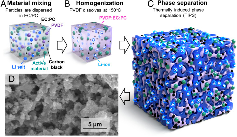
The focus of this work is the development of high areal loading LIB electrodes using TIPS. Several phase-separation methods have been developed over the years to create bicontinuous phases of immiscible components in various mixtures such as polymer blends, ceramics, metal alloys, and organic–inorganic composites (19–22). Prior work focusing on thermoreversible gelation processes has shown the solubility of polyvinylidene fluoride (PVDF) in propylene carbonate (PC) highly dependent on temperature (23). We found that above 150 °C, PVDF can be dissolved in ethylene carbonate(EC):propylene carbonate (PC), but at room temperature it phase-separates and forms a bicontinuous PVDF–solvent network (24). This is interesting because PVDF is a common LIB electrode binder, and EC:PC can be used as an electrolyte solvent. A second important observation is that relatively small volume fractions of PVDF (<20 wt %) can drive the phase segregation of solid content. In other words, if PVDF is mixed with active battery particles and conductive additives at 150 °C in EC:PC with electrolyte salts [e.g., bis(trifluoromethane)sulfonimide lithium salt (LiTFSI)], it will form a homogeneous suspension, but when the suspension cools down, the PVDF binder phase segregates, taking with it the battery particles and conductive additive. The latter forms a solid porous electrode with good electron transport that is interlaced with a bicontinuous network of EC:PC–LiTFSI electrolyte (Fig. 1). We will refer to these as TIPS electrodes. The choice of LiTFSI is motivated by the thermal, moisture, and atmospheric stability (25, 26). Considering LiTFSI is being used for aqueous LIB system, LiTFSI would be handled in room environment (27, 28). However, this does not mean that LiPF6 cannot be used in this process, but it would require a more controlled environment (e.g., dry room).
Fig. 1.
TIPS electrode preparation process. (A) The components of the electrode (active material, carbon black, PVDF, and 1 M LiTFSI in EC/PC) are mixed. (B) The PVDF is dissolved in the electrolyte solvents by mixing at 150 °C. (C) While cooling down, a porous structure is formed via TIPS. (D) Cross-sectional SEM image of representative TIPS electrode showing the internal pore structure (the electrolyte is fully dried for SEM imaging, which is not needed to prepare TIPS-based batteries).
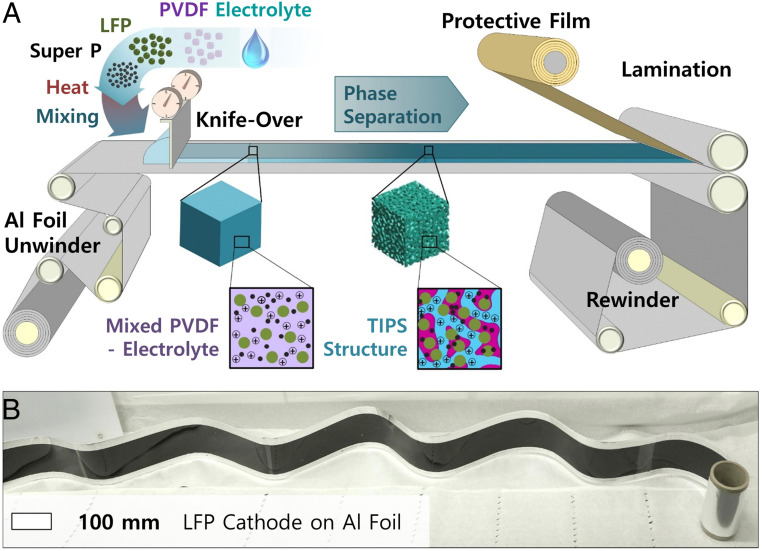
We first investigate the TIPS process using lithium iron phosphate (LFP) cathodes and lithium titanate (LTO) anodes, because 1) their rate performance is good (29–31); hence, they allow us to study kinetics of our bicontinuous phase without being limited by the active materials; 2) they are industrially relevant and cost-effective (32); 3) their voltage plateaus are flat, which facilitates the interpretation of electrochemical measurements; and 4) they are electrochemically stable and their volume changes are minimal (33, 34). The latter is important to study the stability of the TIPS-processed electrodes without being limited by active material degradation. As illustrated in Fig. 1, the fabrication process starts by mixing PVDF, active materials (LFP or LTO), carbon black as a conductive additive, and 1 M LiTFSI in EC:PC (1:1 by volume) solution. This mixture is then heated to 150 °C to form a viscous homogeneous polymer solution, which is coated to different thicknesses. An important advantage of TIPS over other processes for structuring thick electrodes is that it only relies on changes in material solubility with temperature. It is therefore easy to scale up and suitable for manufacturing thick battery electrodes in high throughput. In addition, an important aspect of this fabrication process is that an electrolyte is used to mix the electrode and therefore no solvent drying is needed, which represents important energy savings (especially for thick electrodes which are slow to dry) (35). This drying-free electrode fabrication approach also addresses the cracking and flaking problems which occur during the drying of classic thick battery electrodes (18). To verify the scalability of the proposed TIPS process, it was tested on a continuous R2R coater to fabricate meter-long electrodes with an approximate thickness of 500 µm (Fig. 2A). In this process, the electrolyte is mixed at high temperature with the active material, carbon additive, and binder and then continuously coated on Al foil using a metered knife-over process (Movies S1 and S2). While cooling, the TIPS process induces the bicontinuous phase separation discussed above without requiring any solvent drying or trapping (Fig. 1). The electrode is then laminated with a protective film to increase the shelf life before rewinding (this is an optional step). Fig. 2B shows an example of R2R-coated TIPS LFP cathode. Classic thick electrodes tend to suffer from reduced flexibility (6), which complicates their assembly into cylindrical and prismatic cells. Also, the R2R-coated TIPS electrode did not show any sign of delamination from the current collector when bending, as shown in SI Appendix, Fig. S1.
Fig. 2.
Scalability of the TIPS coating process; (A) compatibility of TIPS electrodes with R2R coating. The homogenized PVDF/electrolyte is coated at high temperature and phase segregates into a bicontinuous electrode with embedded electrolyte. (B) Several meters long and 500-μm-thick LFP TIPS electrode coated on an Al foil by R2R.
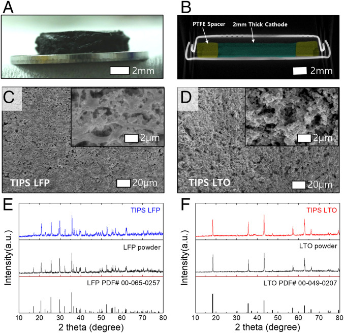
In what follows, we discuss coin-cell experiments for measuring the electrochemical performance of the TIPS electrodes. The electrodes were coated on a glass substrate with thicknesses varying from 0.5 to 2 mm, and cut in disks with diameters of 10 mm as shown in Fig. 3A and SI Appendix, Fig. S2. Note that the Al current collectors used to demonstrate R2R coating are not used here because they are known to corrode at ∼3.7 V vs. Li/Li+ when LiTFSI salt is used (36). This problem can be mitigated by high-concentration electrolyte or electrolyte additives such as LiPF6 and LiBOB (26, 37). For simplicity, the electrodes are placed directly in the coin-cell caps without Al foil in the following experiments. Polytetrafluoroethylene (PTFE) rings with a thickness matching that of the electrodes are placed around the electrode to ensure their thickness is not affected by the mechanical forces of the coin-cell crimping process. We verified by X-ray tomography that a 2-mm-thick TIPS electrode mounted in a CR2032 is not damaged during crimping (Fig. 3B). We also attempted to use X-ray tomography to resolve the microstructure of the electrode but unfortunately the difference in radiodensity between the electrolyte and the electrode is too small in comparison with the steel casing. Scanning electron microscope (SEM) images of the electrode surface and cross-section presented in Fig. 3 C and D and SI Appendix, Fig. S3 show micropores which are important for ion transport in thick electrodes (38, 39). X-ray diffraction (XRD) data in Fig. 3 E and F show the crystal structure of LFP and LTO is not affected after the TIPS electrode casting process.
Fig. 3.
TIPS electrode characterizations. (A) optical image of 2-mm LFP TIPS electrode on a 1-mm spacer. (B) Computed tomography scan image of a 2-mm LFP electrode in a coin cell. The LFP electrode and PTFE spacer are false colored with pine green and olive green, respectively. (C and D) SEM images of molded LTO and LFP electrodes, and (E and F) XRD patterns of pristine and TIPS-processed LFP and LTO particles.
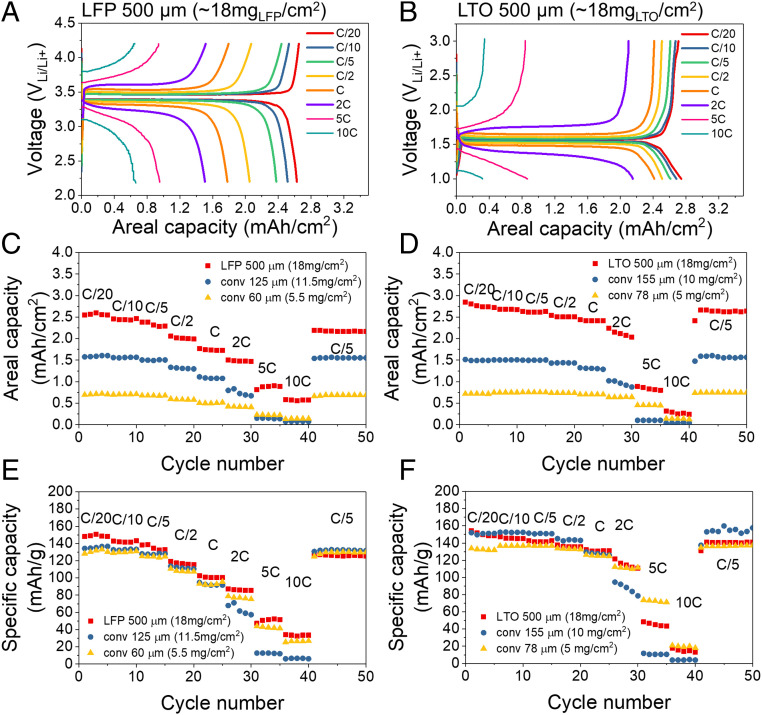
Fig. 4 A and B show the charge–discharge profiles of 0.5-mm-thick LFP cathodes and LTO anodes for rates between C/20 and 10C (loading of ∼18 mg of active materials per cm2). These 0.5-mm-thick electrodes show an excellent utilization of the active material, and despite their thickness, they retain over 50% of their capacity as the rate increases from C/20–2C. For comparison, conventional electrodes using the same starting LFP and LTO material were tested using two different loading levels. The conventional LFP cathodes have areal loadings of 5.5 and 11.5 mg/cm2, and thicknesses of 60 and 125 μm, respectively, whereas the conventional LTO anodes have areal loadings of 5 and 10 mg/cm2 and are 78 and 155 μm thick, respectively (see Fig. 4 C–F). Despite having a 60–75% higher areal loading than conventional electrodes, the TIPS electrodes show a similar specific capacity at slow rate (Fig. 4 E and F at C/20), which indicates that the active material in thick TIPS electrode is very well utilized. In addition, at high rates (10C), the specific capacity of the TIPS electrodes is very close to that of the conventional electrodes (about 10% higher for LFP and 10% lower for LTO). The real merit of the proposed thick electrodes is their enhanced areal capacity (Fig. 4 C and D), which is about 5 times higher than conventional electrodes at C/2 because of their high material loading. Even at high rates (10C), 500-µm-thick TIPS electrodes outperform the areal capacities of conventional electrodes. This is remarkable, because the diffusion time scales with thickness squared (40). The reason our TIPS electrodes are able to maintain such high rate performance is probably a result of the electrode porosity and tortuosity resulting from the TIPS phase-segregation process. The porosity, tortuosity, and thickness of electrodes are driving factors in the rate performance (41, 42), but unfortunately, measuring the porosity and tortuosity of TIPS electrode is challenging because the pores are de facto filled with electrolyte, which makes focused ion beam-SEM imaging impossible and results in poor contract in micro-computed tomography (micro-CT). In addition to the porosity and tortuosity, the interconnection of pores which is achieved in this study by creating a bicontinuous network might further help achieving high rate performance (12). Finally, the TIPS process might help concentrating and compact the carbon conductive additive better with the active material, which would help achieve the relatively low polarization at high rate (Fig. 4 A and B) despite the thickness of the electrodes. We have verified this using four-point probe measurements, which show a conductivity of 0.06 S/cm for classic electrodes and 0.15 S/cm for TIPS electrodes with the same material formulation.
Fig. 4.
Rate performance of 500-µm LFP (Left) and LTO (Right) electrodes. (A and B) Charge–discharge profiles. (C and D) Areal capacities and (E and F) gravimetric capacities of LFP and LTO electrodes at different C rate.
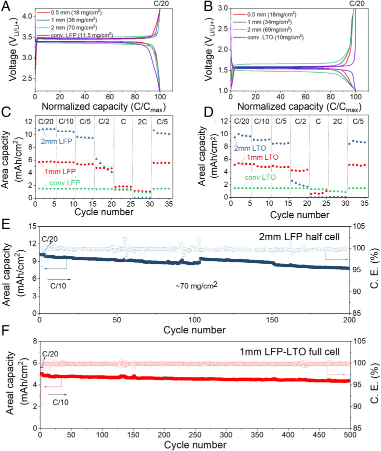
The above experiments are used as a starting point to investigate the electrochemical performance of 1- and 2-mm-thick electrodes with even higher areal loadings. Fig. 5 A and B show charge–discharge voltage profiles of 1- and 2-mm-thick LFP and LTO TIPS electrodes compared with conventional LFP and LTO electrode formulations. At C/20, all LFP and LTO electrodes show a similar polarization indicating that the TIPS electrodes offer a good electrical conductivity. This is confirmed by electrochemical impedance spectroscopy (EIS) analysis, which shows a lower series and charge-transfer resistance in 2-mm-thick TIPS electrodes compared to 60-µm-thick conventional electrodes. (SI Appendix, Fig. S4) As the C rate is ramped-up from C/10 to C/2, the polarization increases as expected for the 2-mm-thick LFP and LTO electrodes (SI Appendix, Fig. S5). The areal capacities of LFP and LTO electrodes at different rates are shown in Fig. 5 C and D. The areal capacity of 2-mm-thick electrodes is about two times higher than 1-mm-thick electrode up to C/5, but at higher C rates, the areal capacity of the 2-mm electrodes derates more rapidly than 1-mm electrodes as expected.
Fig. 5.
Electrochemical performance of ultrathick electrodes. (A and B) Charge–discharge profiles of LFP and LTO with different thickness. (C and D) Areal capacities of LFP and LTO electrodes at different C rate, and capacity retention of (E) 2-mm LFP in half-cell and (F) 1-mm LFP–1-mm LTO full cell.
The cyclability of ultrathick electrodes reported in literature is typically limited. To the best of our knowledge, only 20–50 cycles are reported in literature for electrodes with comparable areal capacity (7, 17, 18). As shown in Fig. 5E, our TIPS LFP electrodes with an areal loading of 70 mg/cm2 were cycled up to 200 times in half-cells, and showed similar capacity retention as conventional electrodes with a low areal loading of 5.5 mg/cm2, and better capacity retention than conventional electrodes with a loading of 11.5 mg/cm2 (SI Appendix, Fig. S6). Next, LFP and LTO TIPS electrodes are tested in full cells to investigate longer-term cycling. As shown in Fig. 5F, full cells with 1-mm LFP cathodes and 1-mm LTO anodes demonstrate an outstanding capacity retention of ∼87% after 500 cycles which is an order of magnitude longer than previous studies on thick electrodes (7, 17). The areal capacities of 1 mm LFP–1 mm LTO cell are ∼5.5 mAh/cm2 (energy density ∼118 mWh/ganode+cathode) at C/20 and 4.5–5.0 mAh/cm2 at C/10. The first-cycle Coulombic efficiency is 90.7%, and the subsequent average Coulombic efficiency is 99.84% (±0.14). Furthermore, ultrathick 2,450 coin cells are used to test the areal capacity of full cells using 2-mm anodes and cathodes, which resulted in a doubling of the areal capacity to ∼10 mAh/cm2, with ∼85% capacity retention over 100 cycles as shown in SI Appendix, Fig. S7.
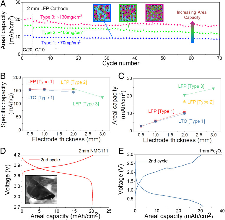
The areal capacity of our electrodes can be enhanced even further by reducing the volume of electrolyte mixed in the electrode. To investigate this, we prepare TIPS electrodes with three different LFP fractions by compressing the electrode discussed above. These electrodes will be referred to as type 1 (lowest density ∼350 mgLFP/cm3), type 2 (∼525 mgLFP/cm3), and type 3 (highest density ∼650 mgLFP/cm3). SEM analysis (SI Appendix, Fig. S8) shows the reduction in pore size as the electrode density increases. By enhancing the active material fraction, the areal capacity of 2-mm-thick electrodes can be increased from 10.9 mAh/cm2 (type 1 at C/20, theoretical capacity ∼11.8 mAh/cm2) to 16.8 mAh/cm2 (type 2 at C/20, theoretical capacity ∼18.3 mAh/cm2), and 20.6 mAh/cm2 (type 3 at C/20, theoretical capacity ∼22.9 mAh/cm2) (Fig. 6A). As shown in Fig. 6B, ∼90% of the theoretical capacity is retained for 2-mm-thick electrodes and ∼74% for 3-mm-thick electrodes. As a result, the areal capacity of TIPS electrodes is increasing linearly with thickness up to 2-mm electrodes and then tapers off for 3-mm-thick electrode. Nevertheless, the latter allows increasing the areal capacity to 24.3 mAh/cm2 at C/20 (theoretical capacity ∼32.8 mAh/cm2) (Fig. 6C). We also verified the structural stability of type 3 LFP electrodes by SEM imaging before and after cycling 70 times, which did not show significant changes (SI Appendix, Fig. S9).
Fig. 6.
Comparison of TIPS electrodes with different electrode densities and active materials. (A) Capacity retention of 2-mm-thick LFP electrodes with three different densities. (B) Specific capacities and (C) areal capacities as a function of the TIPS electrode thickness. (D) Charge–discharge profiles of 2-mm-thick TIPS NMC111 cathode. (Inset) Bent 1-mm NMC111 TIPS electrode) and (E) Charge–discharge profiles of 1-mm-thick TIPS Fe3O4 anode at C/20.
Type 1 bicontinuous TIPS electrodes have a larger pore structure than classic dense electrodes and therefore they have a lower volumetric performance. The improved density in type 3 TIPS electrodes (see SI Appendix, Fig. S8) is therefore important to maintain an overall good volumetric performance. SI Appendix, Fig. S10A compares the thickness a 3-Ah full cell (typical for mobile phone applications) would have if it were using conventional electrodes (Fig. 4, ∼70 μm thick, 10-cm2 double-side coated) and TIPS electrodes (2-mm-thick types 1 and 3). Type 1 TIPS electrodes would result in thicker battery than conventional electrodes. However, type 3 electrodes with a smaller inactive pore fraction achieve higher overall volumetric densities (thinner) than conventional cells. This is further illustrated in SI Appendix, Fig. S10B, which compares the volumetric and areal capacities of different types of conventional and TIPS electrodes and shows the improvements in volumetric capacities achieved by type 3 electrodes. Finally, TIPS electrodes would significantly reduce the fabrication cost of batteries as they require less cutting and stacking steps, use smaller amounts of expensive separators and current collectors, and do not require electrode drying which is an energy-intensive process (43).
Finally, it is worth mentioning that the proposed TIPS process is not limited to LTO and LFP as active materials. For instance, we fabricated electrodes using a cathode material with a higher operating potential (NMC111) and anodes relying on a conversion storage mechanism (Fe3O4) with higher gravimetric capacity. We tested 2-mm-thick NMC111 cathodes (theoretical capacity 37.4 mAh/cm2) and 1-mm Fe3O4 anodes (theoretical capacity 49.8 mAh/cm2) which reached areal capacities of 20.4 and 30.2 mAh/cm2 at C/20 with gravimetric capacities of 150 and ∼560 mAh/g, respectively (Fig. 6 D and E). It should be cautioned that the increase in areal capacity achieved by conversion-type anodes comes at the cost of a shorter cycling stability. Nevertheless, these experiments indicate that TIPS is a versatile process that can be used to structure a range of different battery materials. Furthermore, the TIPS process can also be used to fabricate separators (see experimental details in Materials and Methods), which allows fabrication of batteries where the anode, cathode, and separator are all fabricated by TIPS. We demonstrate this using an NMC-LTO full cell with a TIPS separator (SI Appendix, Fig. S11), which shows good stability and charge–discharge profiles in accordance with those found for commercial separators discussed above. An interesting aspect of these electrodes is that the anode, cathode, and separator can be cast. This hot-casting process can also be used to fabricate large-area electrodes, as illustrated by an 0.8-m-long and 2-mm-thick electrode in SI Appendix, Fig. S12. Finally, we verified that the thick-TIPS electrodes proposed in this work are mechanically flexible and electrochemically fully functional after 100 folding–unfolding cycles to a bending radius of 1 mm (SI Appendix, Figs. S13 and S14).
This paper shows a process for fabricating high areal loading LIB electrodes using a bicontinuous phase-segregation process. We use the electrolyte as the solvent that drives the segregation process, and therefore no solvent drying is needed in this method. This way, electrode cracking or flaking problems that normally occur in thick electrodes are eliminated. As a result, we have been able to continuously coat 0.5-mm-thick cathodes using an R2R coater and to cast electrodes to thicknesses of 3 mm. TIPS electrodes that are 0.5 mm thick outperform the areal capacity classic electrode formulations using the same active material, even at relatively fast rates (2–10 C) despite having a two to three times higher areal loading. Further, we demonstrate that by changing the electrode thickness and density, the battery energy and power requirements can be tuned, with areal capacities reaching up to 30.3 mAh/cm2. Finally, we demonstrate capacity retentions of 87% over 500 cycles in a full cell with 1-mm-thick anodes and cathodes.
Materials and Methods
TIPS Structure Electrodes.
The active materials (LFP, LTO, and NMC111 purchased from MTI Corporation), carbon black (VWR), PVDF (Arkema Inc.) and 1 M LiTFSI in PC:EC (1:1, v:v) were mixed at 150 °C in an argon glovebox (<0.5 ppm of H2O and O2, MBraun) for electrochemically active TIPS electrodes. The ratio of active material: carbon black:PVDF was 70:10:20 by weight. The liquid-state active materials at the elevated temperature are poured onto the glass substrate and flat films with different thickness (0.5; 1; 2 mm) produced in the glovebox. Three different types of electrodes with different active mass loadings are prepared; TIPS electrode type 1: ∼350 mg/cm3, type 2: ∼525 mg/cm3, and type 3: ∼650 mg/cm3. The ratio between active material, carbon black, and PVDF remained the same in all three electrodes but the LiTFSI-containing solvent fraction was changed. The mass ratio between electrode parts (active material, carbon black, and PVDF) and electrolyte parts (LiTFSI and solvents) are 1:2.6 for type 1 electrode. The type 2 and 3 electrodes have much lower liquid fraction; hence, the viscosity of hot liquid is too high to stir with magnetic bar. For convenience, we removed electrolyte after molding of type 1 electrode. Type 2 electrode is prepared by compressing type 1 electrode, and type 3 electrode is prepared with further compression. The mass of electrodes are monitored and the active mass of type 2 and 3 electrodes are tracked by full evaporation of solvents. The mass loadings in different electrode type are reproducible. To ensure that the thickness to the electrodes is not changed while crimping the coin cell, a PTFE spacer with the same thickness as the electrode is mounted in the cell to take up the mechanical load during crimping. The TIPS electrolyte was prepared by mixing PVDF and 1 M LiTFSI in PC:EC (1:1, v:v) at 150 °C in an argon glovebox and the ratio of EC/PC: PVDF was 4:1 by weight. The liquid-state electrolyte was poured onto the glass substrate to form 500-μm-thick film.
Cell Assembly and Electrochemical Characterization.
All battery electrodes are prepared in disk shape with 10 mm diameter. 2032 coin cells are assembled with 0.5-, 1-, and 2-mm TIPS electrodes paired with 0.6 mm Li metal disk. Electrodes with thicknesses of 0.5- and 1-mm electrodes are assembled with 1-mm spacer and a spring and, for 2-mm electrode, only 0.2-mm spacer is used without spring. To prepare 2-mm LFP–2-mm LTO full cell and 3-mm half-cell, 2,450 coin cells are assembled with 1-mm spacer and a spring. The LFP electrodes are cycled between 4.2 and 2.2 V, the NMC111 electrodes are cycled between 4.2 and 2.7 V, the Fe3O4 electrodes are cycled between 0.05 and 3.0 V, and the LTO electrode are cycled between 1.0 and 3.0 V at various C rate in galvanostatic mode via LANHE battery test system. Freestanding TIPS electrodes are used for electrochemical analysis. The C rate is the rate at which a battery is charged/discharged relative to its theoretical capacity. The LFP-LTO full cells are cycled between 2.4 and 1.0 V and the NMC111-LTO full cells are cycled between 2.7 and 1.2 V at C/20 and C/10 in galvanostatic mode. The areal capacity (mAh/cm2) is calculated by dividing capacity by the area of active electrodes.
Other Characterization.
R2R-coated 0.5-mm LFP electrodes on Al foil are prepared by Smartcoater 28. (Coatema Coating Machinery GmbH). The protective film used in R2R process is polyethylene terephthalate (PET) and it is simply used to increase the shelf-life by minimizing evaporation of solvents and accidental contamination as our TIPS electrode contains solvents. This is not a necessary component in actual battery fabrication process as the TIPS electrodes can directly assemble into the cell without drying. Micro-CT data are obtained at the Cambridge Tomography Centre with a Nikon XTH225 ST scanner. Morphologies of LFP and LTO electrodes are observed by high-resolution SEM (LEO1530) with an acceleration voltage of 5 kV and a working distance of 4 mm. The XRD patterns are acquired via a Bruker D8 Advance (Cu Kα radiation, 6° min−1 scan). EIS tests are scanned from 0.1 to 106 Hz with an amplitude of 10 mV using a Biologic VMP3.
Supplementary Material
Acknowledgments
This work was supported by European Research Council starting grant under Award MIGTHY–866005 and Marie Skłodowska-Curie Individual Fellowship under Projects MSCA-IF 838403–ULTIMATE and MSCA-IF 796648–URCHIN. This work was also supported by the National Research Foundation of Korea (NRF) Grant funded by the Korean government (MEST) (No. NRF-2020R1C1C1003656). The PVDF powders were generously supplied by Arkema Inc.
Footnotes
The authors declare no competing interest.
This article is a PNAS Direct Submission.
This article contains supporting information online at https://www.pnas.org/lookup/suppl/doi:10.1073/pnas.2007250117/-/DCSupplemental.
Data Availability.
All data needed to support the conclusions presented in this paper are available in the manuscript, SI Appendix and, Datasets S01–S19.
References
- 1.Schmuch R., Wagner R., Hörpel G., Placke T., Winter M., Performance and cost of materials for lithium-based rechargeable automotive batteries. Nat. Energy 3, 267–278 (2018). [Google Scholar]
- 2.Nitta N., Wu F., Lee J. T., Yushin G., Li-ion battery materials: Present and future. Mater. Today 18, 252–264 (2015). [Google Scholar]
- 3.Etacheri V., Marom R., Elazari R., Salitra G., Aurbach D., Challenges in the development of advanced Li-ion batteries: A review. Energy Environ. Sci. 4, 3243–3262 (2011). [Google Scholar]
- 4.Singh M., Kaiser J., Hahn H., Thick electrodes for high energy lithium ion batteries. J. Electrochem. Soc. 162, A1196–A1201 (2015). [Google Scholar]
- 5.Vlad A., Singh N., Galande C., Ajayan P. M., Design considerations for unconventional electrochemical energy storage architectures. Adv. Energy Mater. 5, 1402115 (2015). [Google Scholar]
- 6.Heider E., et al. , “Key features in the manufacturing process of ultra-thick electrodes for high energy lithium ion batteries” in Meeting Abstracts (The Electrochemical Society, 2019), 181. [Google Scholar]
- 7.Elango R., Demortière A., Andrade V., Morcrette M., Seznec V., Thick binder‐free electrodes for Li–ion battery fabricated using templating approach and spark plasma sintering reveals high areal capacity. Adv. Energy Mater. 8, 1703031 (2018). [Google Scholar]
- 8.Huang C., Grant P. S., Coral-like directional porosity lithium ion battery cathodes by ice templating. J. Mater. Chem. A Mater. Energy Sustain. 6, 14689–14699 (2018). [Google Scholar]
- 9.Wang Y. et al., Ice templated free‐standing hierarchically WS2/CNT‐rGO aerogel for high‐performance rechargeable lithium and sodium ion batteries. Adv. Energy Mater. 6, 1601057 (2016). [Google Scholar]
- 10.Sander J., Erb R. M., Li L., Gurijala A., Chiang Y.-M., High-performance battery electrodes via magnetic templating. Nat. Energy 1, 16099 (2016). [Google Scholar]
- 11.Billaud J., Bouville F., Magrini T., Villevieille C., Studart A. R., Magnetically aligned graphite electrodes for high-rate performance Li-ion batteries. Nat. Energy 1, 16097 (2016). [Google Scholar]
- 12.Zhang H., Yu X., Braun P. V., Three-dimensional bicontinuous ultrafast-charge and -discharge bulk battery electrodes. Nat. Nanotechnol. 6, 277–281 (2011). [DOI] [PubMed] [Google Scholar]
- 13.Sakamoto J. S., Dunn B., Hierarchical battery electrodes based on inverted opal structures. J. Mater. Chem. 12, 2859–2861 (2002). [Google Scholar]
- 14.Jessl S., Copic D., Engelke S., Ahmad S., De Volder M. J. S., Hydrothermal coating of patterned carbon nanotube forest for structured lithium‐ion battery electrodes. Small 15, 1901201 (2019). [DOI] [PubMed] [Google Scholar]
- 15.Evanoff K. et al., Towards ultrathick battery electrodes: Aligned carbon nanotube-enabled architecture. Adv. Mater. 24, 533–537 (2012). [DOI] [PubMed] [Google Scholar]
- 16.Shen F. et al., Ultra‐thick, low‐tortuosity, and mesoporous wood carbon anode for high‐performance sodium‐ion batteries. Adv. Energy Mater. 6, 1600377 (2016). [Google Scholar]
- 17.Lu L. L. et al., Wood-inspired high-performance ultrathick bulk battery electrodes. Adv. Mater. 30, e1706745 (2018). [DOI] [PubMed] [Google Scholar]
- 18.Park S.-H. et al., High areal capacity battery electrodes enabled by segregated nanotube networks. Nat. Energy 4, 560–567 (2019). [Google Scholar]
- 19.Lloyd D. R., Kinzer K. E., Tseng H., Microporous membrane formation via thermally induced phase separation. I. Solid-liquid phase separation. J. Membr. Sci. 52, 239–261 (1990). [Google Scholar]
- 20.Kim D., Kim W., Park E., Mattern N., Eckert J., Phase separation in metallic glasses. Prog. Mater. Sci. 58, 1103–1172 (2013). [Google Scholar]
- 21.Erlebacher J., Aziz M. J., Karma A., Dimitrov N., Sieradzki K., Evolution of nanoporosity in dealloying. Nature 410, 450–453 (2001). [DOI] [PubMed] [Google Scholar]
- 22.Jo C. et al., Multiscale phase separations for hierarchically ordered macro/mesostructured metal oxides. Adv. Mater. 30, 1703829 (2018). [DOI] [PubMed] [Google Scholar]
- 23.Akkoyun M., Carrot C., Blottière B., Ternary Diagrams of Poly(vinylidene fluoride) and Poly[(vinylidene fluoride)‐co‐hexafluoropropene] in Propylene Carbonate and Dimethyl Sulfoxide. Macromol. Chem. Phys. 213, 587–593 (2012). [Google Scholar]
- 24.Periasamy P. et al., Studies on PVdF-based gel polymer electrolytes. J. Power Sources 88, 269–273 (2000). [Google Scholar]
- 25.Andersson A. M., Herstedt M., Bishop A. G., Edström K., The influence of lithium salt on the interfacial reactions controlling the thermal stability of graphite anodes. J. Electrochimica Acta 47, 1885–1898 (2002). [Google Scholar]
- 26.Matsumoto K. et al., Suppression of aluminum corrosion by using high concentration LiTFSI electrolyte. J. Power Sources 231, 234–238 (2013). [Google Scholar]
- 27.Yamada Y. et al., Hydrate-melt electrolytes for high-energy-density aqueous batteries. Nat. Energy 1, 1–9 (2016). [Google Scholar]
- 28.Suo L. et al., “Water-in-salt” electrolyte enables high-voltage aqueous lithium-ion chemistries. Science 350, 938–943 (2015). [DOI] [PubMed] [Google Scholar]
- 29.Yang Z. et al., Nanostructures and lithium electrochemical reactivity of lithium titanites and titanium oxides: A review. J. Power Sources 192, 588–598 (2009). [Google Scholar]
- 30.Huang H., Yin S.-C., Nazar L. F., Approaching theoretical capacity of LiFePO4 at room temperature at high rates. Electrochem. Solid State Lett. 4, A170–A172 (2001). [Google Scholar]
- 31.Zaghib K. et al., Safe and fast-charging Li-ion battery with long shelf life for power applications. J. Power Sources 196, 3949–3954 (2011). [Google Scholar]
- 32.Jaiswal A., Lithium-ion battery based renewable energy solution for off-grid electricity: A techno-economic analysis. Renew. Sustain. Energy Rev. 72, 922–934 (2017). [Google Scholar]
- 33.Scrosati B., Garche J., Lithium batteries: Status, prospects and future. J. Power Sources 195, 2419–2430 (2010). [Google Scholar]
- 34.Padhi A. K., Nanjundaswamy K. S., Goodenough J. B., Phospho‐olivines as positive‐electrode materials for rechargeable lithium batteries. J. Electrochem. Soc. 144, 1188–1194 (1997). [Google Scholar]
- 35.Wood D. L., Li J., Daniel C., Prospects for reducing the processing cost of lithium ion batteries. J. Power Sources 275, 234–242 (2015). [Google Scholar]
- 36.Yang H., Kwon K., Devine T. M., Evans J. W., Aluminum corrosion in lithium batteries an investigation using the electrochemical quartz crystal microbalance. J. Electrochem. Soc. 147, 4399–4407 (2000). [Google Scholar]
- 37.Zhang S. S., A review on electrolyte additives for lithium-ion batteries. J. Power Sources 162, 1379–1394 (2006). [Google Scholar]
- 38.Wang B., Al Abdulla W., Wang D., Zhao X., A three-dimensional porous LiFePO 4 cathode material modified with a nitrogen-doped graphene aerogel for high-power lithium ion batteries. Energy Environ. Sci. 8, 869–875 (2015). [Google Scholar]
- 39.Sun C., Rajasekhara S., Goodenough J. B., Zhou F., Monodisperse porous LiFePO4 microspheres for a high power Li-ion battery cathode. J. Am. Chem. Soc. 133, 2132–2135 (2011). [DOI] [PubMed] [Google Scholar]
- 40.Bruce P. G., Scrosati B., Tarascon J. M., Nanomaterials for rechargeable lithium batteries. Angew. Chem. Int. Ed. Engl. 47, 2930–2946 (2008). [DOI] [PubMed] [Google Scholar]
- 41.Suthar B., Northrop P. W., Rife D., Subramanian V. R., Effect of porosity, thickness and tortuosity on capacity fade of anode. J. Electrochem. Soc. 162, A1708–A1717 (2015). [Google Scholar]
- 42.Doyle M., Fuller T. F., Newman J., Modeling of galvanostatic charge and discharge of the lithium/polymer/insertion cell. J. Electrochem. Soc. 140, 1526 (1993). [Google Scholar]
- 43.Ahmed S., Nelson P. A., Gallagher K. G., Dees D. W., Energy impact of cathode drying and solvent recovery during lithium-ion battery manufacturing. J. Power Sources 322, 169–178 (2016). [Google Scholar]
Associated Data
This section collects any data citations, data availability statements, or supplementary materials included in this article.
Supplementary Materials
Data Availability Statement
All data needed to support the conclusions presented in this paper are available in the manuscript, SI Appendix and, Datasets S01–S19.


