Abstract
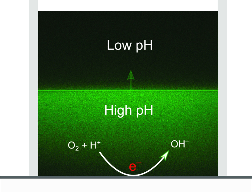
Confocal fluorescence microscopy is a proven technique, which can image near-electrode pH changes. For a complete understanding of electrode processes, time-resolved measurements are required, which have not been achieved previously. Here we present the first measurements of time-resolved pH profiles with confocal fluorescence microscopy. The experimental results compare favorably with a one-dimensional reaction–diffusion model; this holds up to the point where the measurements reveal three-dimensionality in the pH distribution. Specific factors affecting the pH measurement such as attenuation of light and the role of dye migration are also discussed in detail. The method is further applied to reveal the buffer effects observed in sulfate-containing electrolytes. The work presented here is paving the way toward the use of confocal fluorescence microscopy in the measurement of 3D time-resolved pH changes in numerous electrochemical settings, for example, in the vicinity of bubbles.
Electrochemical reactions in aqueous solutions are strongly affected by the pH near the electrode. In corrosion science, potential–pH phase diagrams1 (Pourbaix diagrams) best summarize this relationship. Moreover, in applications of energy storage and material conversion (e.g., CO2 and N2 reduction to useful products), where protons in solution are consumed, there is a direct link between the pH and the efficiency of the electrochemical cell. Measuring and understanding pH profiles near electrodes is therefore essential and can provide insight into the local surface chemistry and help design efficient electrochemical systems. This is particularly relevant in the reduction of CO2, where sensitivity to the near electrode pH may limit the desired product formation.2−4
An effective technique to detect pH changes is the use of indicator molecules, such as fluorescein, whose fluorescence changes with pH. Unlike point measurements, e.g., via scanning electrochemical microscopy,5 imaging fluorescence fields allows for spatially resolved pH measurement. When coupled with confocal microscopy, this approach offers an even higher spatial resolution and has already demonstrated its potential in electrochemical applications.6 For example, Unwin et al.7,8 measured three-dimensional steady-state pH profiles on microelectrodes. Cannan et al.7 determined the pH change accompanied by the reduction of benzoquinone to hydroquinone. Similarly, Rudd et al.8 measured the pH profiles induced by the reduction of water and oxygen on gold electrodes. They considered different electrode shapes and compared their results with a steady-state reaction–diffusion model. Leenheer and Atwater9 applied the fluorescence method in a flow cell to compare the steady-state pH profiles formed (for hydrogen evolution) on patterned Au electrode surfaces. Furthermore, they measured pH profiles on various electrode materials, thereby suggesting this technique as a screening tool for identifying electrocatalysts. Leenheer and Atwater9 also they compared their measurements to a steady-state model, one including laminar flow.
Although fluorescent measurements of spatiotemporal pH profiles near ion-selective membranes have been recently undertaken10 with related electrokinetic modeling by Andersen et al.,11 such measurements are lacking for electrolytic systems and near the electrodes. Here, besides electric field effects, large gradients in pH are created because of chemical reactions at the electrode surface. Time resolution is then essential to capture the dynamics at the electrode–electrolyte interface. One such application would be the measurement of pH profiles around growing hydrogen bubbles in solution, which may reveal transient reaction hot-spots.12,13 Similarly, other situations involving phase change, simultaneous electrode reactions, or bulk buffer reactions during electrolysis require time-resolved measurements for their accurate characterization. Certainly, a further development of time-resolved measurements techniques is urgently needed to understand dynamic processes occurring at electrode/electrolyte interfaces in electrochemical processes. In spite of the need, to the best of our knowledge, a quantitative comparison of time-resolved pH measurements and modeling using fluorescent dyes is not yet available in the literature. In this contribution we demonstrate the feasibility of using fluorescent dyes to measure spatiotemporally varying pH profiles in solution by comparing the pH changes arising from electrochemical oxygen reduction with a time-dependent reaction–diffusion model. We further apply this technique to highlight buffer effects in sulfate-containing electrolytes.
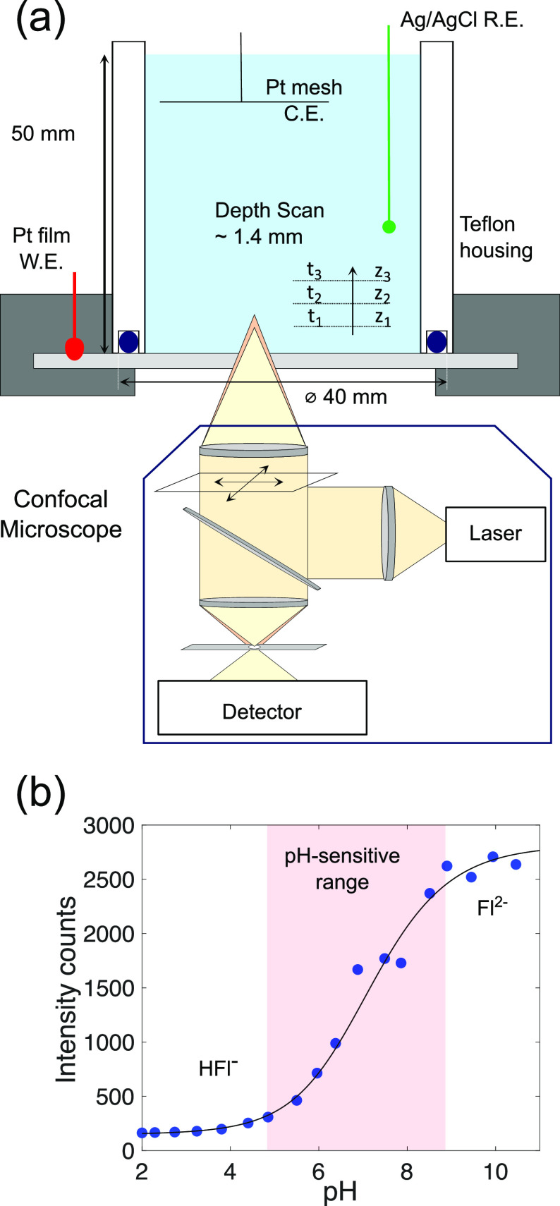
Confocal Fluorescence (pH) Microscopy. To carry out the measurements, an electrochemical cell assembly was mounted on top of an inverted confocal microscope. A schematic of the setup which also contains the relevant dimensions is shown in Figure 1a. The electrochemical housing was made of Teflon. In all measurements, a platinized titanium mesh was rolled up and placed as a ring at about 4 cm from the working electrode. This assembly successfully prevented any interference of the counter electrode reaction with the pH measurement. A 10 nm thick platinum film evaporated on a circular glass slide (thickness 170 μm, diameter 50 mm) formed the working electrode. A BASi Ag/AgCl (in 3 M NaCl) was used as a reference electrode. Unless otherwise stated, 0.5 M NaClO4 with 8 μM sodium fluorescein was used as electrolyte. The measurements involved taking fluorescence images along the scanned direction z (in a serial fashion as shown in Figure 1a). The mean of each image was then taken as the measured intensity at the corresponding z-position. The fluorescence signal was found to be compromised up to a distance z ≈ 100 μm above the surface (see Experimental Section and the Supporting Information for further details). Therefore, any fluorescence intensity (and resulting pH) information was obtained only above this threshold.
Figure 1.
(a) Schematic of the experimental setup. The electrochemical cell was placed on the inverted confocal laser scanning microscope. The transparent working electrode allowed for depth-wise (z) measurement of fluorescent intensity. (b) Calibration results for the pH dependence of fluorescein. The experimental data (filled circles) shown here are the mean of three measurements of intensity measurements at each pH (error bars are smaller than the marker size). A sigmoidal function (black line; see Supporting Information for details of fit) is fitted to all three measurements at each pH. The measurements were performed in 1 mM Na2SO4 containing 8 μM fluorescein. pH was adjusted to the required value by addition of H2SO4.
Fluorescein (Fl) is a popular choice to probe pH changes in electrochemical cells.7−9,14,15 The pH sensitivity of Fl is well documented16−18 and arises from the existence of different protonated forms of the molecule in solution. The fluorescence emission of constant pH solutions was measured for the intensity-to-pH calibration (as shown in Figure 1b). These results were fitted with an analytical function to allow for a conversion from Fl intensities obtained in the experiments to pH. The laser and confocal settings were kept constant throughout the study such that the curve in Figure 1b applies to all experiments. The dye is found to be particularly pH-sensitive in the range 5 ≲ pH ≲ 10 (indicated by the shading in Figure 1b), as evidenced by the pronounced increase of fluorescence emission intensity measured with increasing pH within this interval. However, the highly nonlinear intensity-pH relationship suggests that measurement results beyond pH ≳ 8.5 should be taken with caution. Details on the fit and the repeatability are provided in the Supporting Information. The effect of dye migration induced by the electric field has also been addressed therein. Migration is detrimental to the present technique, which assumes a homogeneous dye distribution. It was found that a certain minimum supporting electrolyte concentration is necessary to keep migration effects at bay.
Last, to compare with experimental results, we also simulated the pH profiles during reaction. Because the supporting electrolyte concentration is high, we adopted a reaction–diffusion model for the simulations of the general form
| 1 |
where ck(z, t) is the concentration of species k, Dk the corresponding diffusion constant, and f(c) a nonlinear function representing reaction terms. Here the chemical reactions considered are
| 2 |
| 3 |
where the equilibrium constants are  and
and  . The pKa of
H2Fl is lower than the pH considered here, and therefore,
it can be ignored. Assuming that the concentration of water is large
and therefore essentially constant during the experiment, the equations
have been solved for the concentration of three species: H+, OH–, and Fl2–. Further details
of the exact reaction–diffusion equations (with their boundary
conditions) and the numerical technique (including validation) are
presented in the Supporting Information. The contribution of capacitive current has also been taken into
account. However, because the exact value of the capacitance (C) is not known in our measurements, results for C values in the range 0 ≤ C ≤
120 μF/cm2 are also presented in Figure 3c. Additional details can be
found in the Supporting Information.
Figure 3.
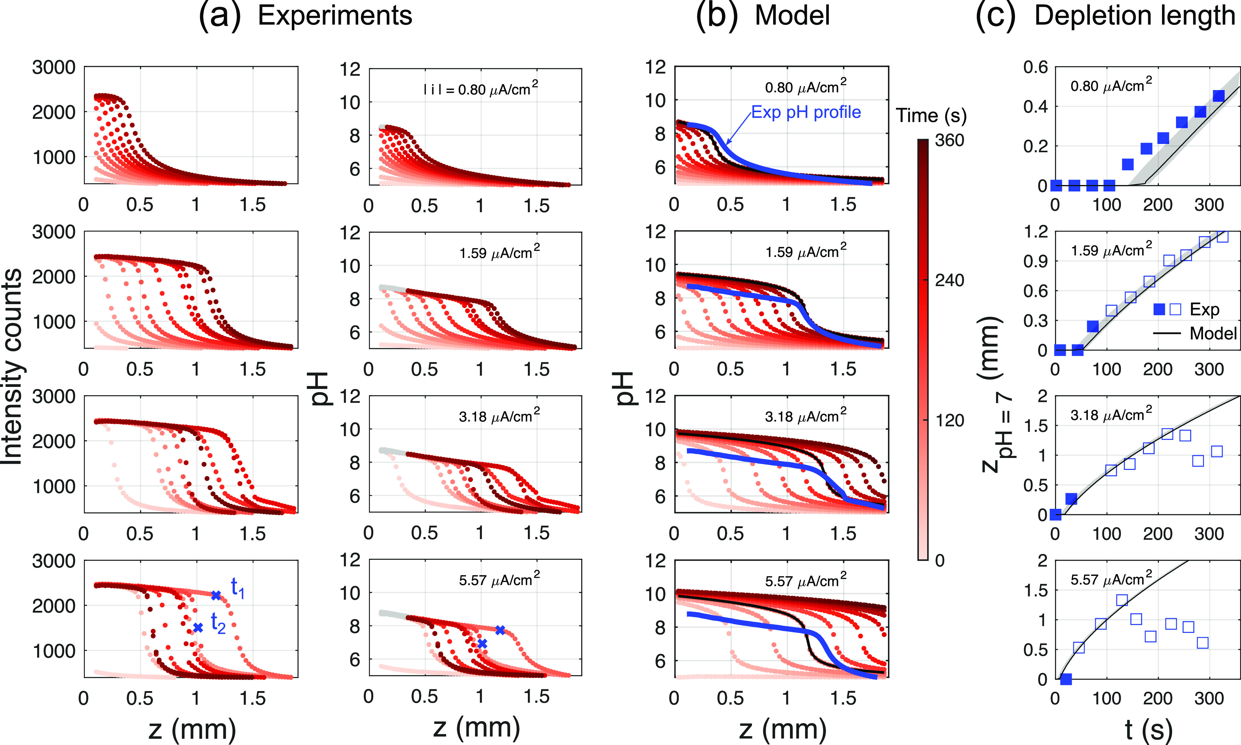
Experimental versus model results. The experimental measurement is restricted to z > 0.1 mm because of limitations of the optical setup (see Supporting Information for details). (a) Attenuation and depth-corrected fluorescein intensity profiles. Corresponding pH profiles calculated using the calibration curve. pH > 8.5 has been grayed out because of the uncertainty in the measurement at these values. The times t1 and t2 have been marked for use in Figure 4. (b) Model results (with C = 88 μF/cm2) calculated at experimental times. The solid lines are drawn to compare pH profiles of the experiment (blue) with the model (black). (c) Comparison of depletion length zpH 7 of experiment versus model. The shaded region indicates the model results over a range of capacitance 0 ≤ C ≤ 120 μF/cm2 (solid line with C = 88 μF/cm2). Open squares show the location of the pH front after the first appearance of the inhomogeneity as shown in Figure 4.
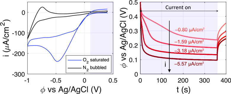
Time-Resolved pH Measurements. A cyclic voltammogramm (CV) of an O2 saturated solution (pH 5 HClO4 + 0.5 M NaClO4 + 8 μM Fl), along with the measured potential of the Pt working electrode for some of the constant current experiments, is shown in Figure 2. For reference, an additional CV is included for the same configuration but using N2-bubbled electrolyte instead. For the current densities, i, and run-times considered here, it is estimated (using an initial concentration corresponding to 1 atm O2 pressure) that the oxygen at the electrode surface never gets completely depleted. This is also evident from the differences between the CV’s of the O2-saturated and N2-bubbled solutions in Figure 2. Hence, it can be concluded that oxygen reduction, and not water or proton reduction, is the primary reaction occurring at the electrode. The measured potential window of operation in our constant current experiments is between 0.1 and 0.5 V vs Ag/AgCl (at a starting pH of 5), which translates to 0.6–1.1 V vs RHE. Given that an ovepotential of |Δϕ| ≳ 0.3 V19 (over the thermodynamic potential of 1.23 V vs RHE) is required to drive the O2 reduction reaction on platinum, the potentials measured in our experiments are consistent with O2 reduction occurring at the electrode. However, because the O2 reduction reaction depends on the pH of the solution,20,21 the proper flux boundary conditions for OH– and H+ are complicated (consumption of H+ or production of OH–, depending on the reaction). Nevertheless, the calculated pH profiles shown here were found to be independent of this. Finally, it is important to mention that fluorescein is stable under the conditions applied.22−24
Figure 2.
Left: First cycle of the cyclic voltammogram (CV) measured at 10 mV/s for the Pt working electrode in O2 saturated and N2 bubbled solutions (pH 5 HClO4 + 0.5 M NaClO4 + 8 μM Fl) in our setup. The shaded region shows the potential range measured in chronopotentiometric (CP) experiments. Right: The CP curves obtained for the O2 saturated case. The shaded region indicates the time over which the constant current is applied. The corresponding current density for each curve is mentioned as well.
The obtained emission intensity profiles and the resulting pH distributions (at 0.5 M NaClO4 supporting electrolyte concentration) are summarized in Figure 3a for various (constant) applied current densities. In all cases considered here, i is limited to values traditionally considered minute for electrochemistry. Despite such low current densities, the pH change and the corresponding thickness of the depletion layer are significant. Figure 3a shows the attenuation-corrected mean intensity of fluorescein emission as a function of distance z from the electrode surface. Independent of the applied current density, a steep front is seen to propagate into the solution already at early times, t < 300 s. This feature also translates to the corresponding pH profiles. It should be noted, however, that intensity levels within the resulting “shoulder” close to the electrode reach the saturation limit and because of the uncertainties described above, pH results are grayed out in these instances. Nevertheless, the experimental results are in good agreement with the simulated pH profiles shown in Figure 3b (see solid lines). Interestingly, also in the simulations the pH is near constant close to the electrode for |i| ≥ 1.59 μA/cm2, yet with pH 9–10, the values are slightly outside the experimental sensitivity range. Even at current densities of ∼1 μA/cm2, the depletion layer or the penetration depth of the pH profile reaches ∼1 mm into the electrolyte. At higher current densities, this depletion length grows faster and extends further into the bulk of the solution.
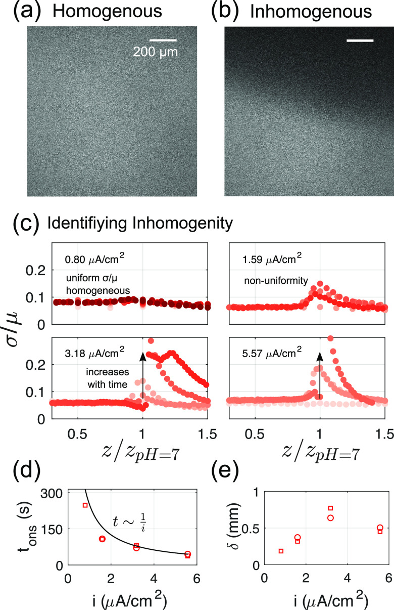
It can be seen, however, that for the two highest current densities considered here, the intensity as well as the pH profiles recede at later times (corresponding to darker shadings of the markers), whereas the model predicts a monotonic outward propagation of the front. To enable a quantitative comparison, we track the position zpH 7 at which pH 7 is encountered as a proxy for the front location. As Figure 3c shows, the pH front propagation in the experiments is well captured by the model for the two lower current density cases presented here. At higher current densities and at late times, though, the pH front in experiments either recedes or saturates. This is also true for repeat measurements made (see the Supporting Information). However, this effect appears to be an artifact of the way the mean fluorescein intensities are calculated. Consistent with the 1D assumption, only a measure of the mean across the entire image (i.e., a plane parallel to the electrode) is considered. For example, at t1 (for |i| = 5.59 μA/cm2, see Figure 3a), this is appropriate as highlighted in Figure 4a. At t2 though, the intensity distribution displayed in Figure 4a becomes distinctly inhomogeneous as seen in Figure 4b. This implies that 2D or 3D effects become relevant, which are not captured in the one-dimensional model.
Figure 4.
Inhomogeneous fluorescein intensity in a plane. Example of fluorescein
intensity images (|i| = 5.59 μA/cm2) at times marked in Figure 3a: (a) homogeneous image at time t1 and (b) inhomogeneous at time t2. (c)
σ/μ versus depth for all current densities. The same color
bar as in Figure 3 applies.
Sharp changes are used to pick out times and positions where this
nonuniformity is observed. (d) The onset time tons and (e) the location δ at which the inhomogeneity
is first observed vs current density. Different symbols are repeat
measurements. The solid line in panel d corresponds to  s and is arbitrarily chosen to highlight
the inverse relationship between tons and i.
To determine the location and time at which 3D effects become relevant, we consider the standard deviation (σ) normalized with the mean intensity (μ) of the image as shown in Figure 4c. To minimize the effect of high-frequency spatial noise, the image was box-filtered with a filter size of 50 pixels before calculating σ. Figure 4c captures the uniform image intensity for |i| = 0.8 μA/cm2 as a near constant σ/μ. In contrast, a visible peak in σ/μ at the depletion front z = zpH 7 is observed for all other cases. At the two highest current densities considered, the unsteadiness in fluorescein intensity develops over time as well. The onset time (tons defined as σ/μ > 0.1) of this instability thus calculated is, in Figure 4d, found to sharply reduce with increasing current densities which is well approximated by an inverse proportionality. It is conceivable then that this instability occurs only after a certain threshold number of H+ ions have been depleted from the solution. The distance δ at which this nonuniformity is first measured shows no clear trend: the nonuniformity first increases until |i| = 3.18 μA/cm2 and then decreases again slightly later. Because we look at only a small portion of the electrode though, deviations from a 1D profile can occur much earlier, at a different δ. It is unlikely that the reaction at the counter electrode plays any role in the appearance of instability as it is sufficiently far compared to the measured depletion lengths of ∼2 mm. Possible reasons could then be the presence of electric field effects or induced fluid flow in the system,25 which have not been modeled. However, despite the early appearance of inhomogeneity, the pH profiles in experiments are similar to the model results up to distances and times that are much larger (see Figure 3c, filled and open symbols, and blue/black lines in Figure 3b). It may be possible then that the departure of pH profiles in experiments, from a 1D diffusion approximation, occurs only after a certain minimum σ/μ (and corresponding inhomogeneity) is reached.
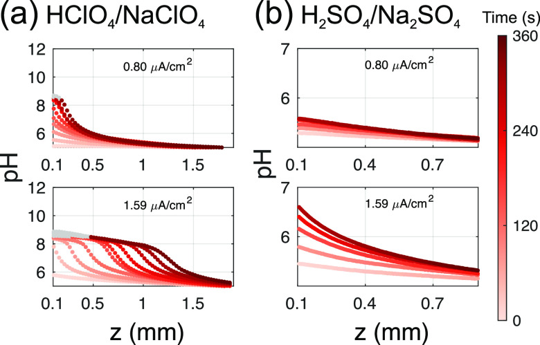
Sulfate Buffer Effect. In addition to the above measurements, we proceed to evaluate the developing pH profiles in sulfate-containing electrolytes, e.g., in the Na2SO4/H2SO4 system. This system is frequently used (for example sulfuric acid is commonly used to study O2 reduction) but, in contrast to perchlorate electrolytes, may induce additional buffer capacity, thus changing the pH profiles. In fact, H2SO4 has two dissociation constants; the second corresponds to the dissociation of HSO4– with a pKa of around 2.26−28Figure 5 compares the pH profiles measured for the sulfate case to those obtained with perchlorate electrolyte, for the two lowest current densites. It is evident that the pH profiles develop significantly slower in sulfate-containing electrolytes. For example, for |i| = 1.59 μA/cm2, the pH profiles in the Na2SO4/H2SO4 system have no clear front propagating in the solution; the profiles rather become increasingly steep close to the electrode surface with time, while for the perchlorate solution depletion lengths of zpH 7 ≈ 1.5 mm are achieved.
Figure 5.
Comparison of pH profiles for (a) perchlorate (NaClO4/HClO4) and (b) sulfate (Na2SO4/H2SO4) electrolytes. All measurements were performed in 0.5 M supporting salt concentration containing 8 μM Fl. pH was adjusted to pH 5 by addition of respective acid. All solutions were bubbled with N2 before starting the experiment. pH > 8.5 has been grayed out because of the uncertainty in the measurements at these values.
To try to further explain the experimental results, we consider the pKa of HSO4–, which, although it is well below our starting pH (pH 5), because of the presence of the large concentration of SO42– in solution, creates a reservoir of HSO4– ions which acts as a source of protons in solution and stabilizes the solution against pH changes. We attempt to capture this effect in the 1D model as our results in the Supporting Information show. This buffer effect is most likely present in experimental measurements in the literature with sulfate electrolytes.5,9 For example, Leenheer and Atwater9 measured the pH on patterned gold electrodes in Na2SO4 solutions, with different pattern shapes and area. However, their steady-state simulations predicted a depletion zone much larger than experiments. Similarly, the buffering effect of Li2SO4 solutions may also be present in the recent measurements by Monteiro et al.5 A comparison such as ours, between perchlorate and sulfate electrolytes, should help to quantify the magnitude of this effect and help better interpret results.
To summarize, we have successfully demonstrated the use of fluorescein to measure time-resolved pH profiles in solution. The results of a time-dependent reaction–diffusion model compare reasonably well with the experimental data. However, the inhomogeneity of pH in a plane that develops at “high currents” clearly shows the need for time-varying local pH measurements. The crucial aspects to consider when using fluorescence microscopy for pH measurement, like optical distortions and signal attenuation, have been carefully examined. Furthermore, the concentration of the supporting electrolyte is shown to influence migration of fluorescent dyes and should be considered to avoid pitfalls in pH measurement in electrochemical systems. For sulfate-containing electrolytes, our analysis reveals buffering effects, which likely explain the difference between the measured diffusion profiles and those observed in experiments in the past.9
Fluorescence microscopy offers time-resolved and relatively nonintrusive measurement of pH instantly over a large area. Because the principle of measurement presented here is applicable to other fluorescent dyes with a different pH detection range, this technique can be used for a wide range of electrochemical systems to elucidate electrode dynamics. This holds in particular for CO2 reduction on gas diffusion electrodes, because the second pKa of carbonic acid lies in the fluorescein detection region. Our developed method can be directly implemented to quantify mass transport, the role of bicarbonate concentrations, etc. in the electrolyte. More generally, the measurement technique presented here offers insight into the dynamics of ions in solution, important to many electrochemical systems, none more so than in electrochemical cells to unravel the role of start–stop transients. Detailed information on the pH distribution will provide a better understanding of electrode processes and aid in the overall design of electrochemical systems for eventual use in large-scale electrolysis.
Experimental Methods
For the working electrode, a 3 nm thick chromium (under) layer was used for better adhesion between the platinum film and the glass slide. The sheet resistance of the resulting thin-film electrode was 69 Ω. The electrical connection to the working electrode was made with a platinized titanium point contact. Prior to the measurement, the pH of the solution was adjusted to a pH value of 5 by addition of appropriate amounts of 0.1 M HClO4 (or 0.5 M H2SO4 for sulfate electrolytes). The pH of the solution before the start of each experiment (as well as the calibration solutions shown in Figure 1b) was measured using the Hannah Instruments Edge-pH meter that has an accuracy of ±0.02 pH units. All chemicals were purchased from Sigma-Aldrich. Further experimental and numerical details can be found in the Supporting Information.
Acknowledgments
This research received funding from The Netherlands Organization for Scientific Research (NWO) in the framework of the fund New Chemical Innovations, project ELECTROGAS (731.015.204), with financial support of Akzo Nobel Chemicals, Shell Global Solutions, Magneto Special Anodes (an Evoqua Brand), and Elson Technologies. We acknowledge The Netherlands Center for Multiscale Catalytic Energy Conversion (MCEC) and the Max Planck Center Twente for Complex Fluid Dynamics for financial support. D.L. also acknowledges financial support by an ERC-Advanced Grant.
Supporting Information Available
The Supporting Information is available free of charge at https://pubs.acs.org/doi/10.1021/acs.jpclett.0c01575.
Details of experimental method, numerical method, repeat measurements and comparison of experiments, and model for sulfates (PDF)
The authors declare no competing financial interest.
Supplementary Material
References
- Pourbaix M.; Zhang H.; Pourbaix A. Presentation of an Atlas of Chemical and Electrochemical Equilibria in the Precence of a Gaseous Phase. Mater. Sci. Forum 1997, 251–254, 143–148. 10.4028/www.scientific.net/MSF.251-254.143. [DOI] [Google Scholar]
- Kas R.; Kortlever R.; Yılmaz H.; Koper M. T. M.; Mul G. Manipulating the Hydrocarbon Selectivity of Copper Nanoparticles in CO2 Electroreduction by Process Conditions. ChemElectroChem 2015, 2, 354–358. 10.1002/celc.201402373. [DOI] [Google Scholar]
- Yang K.; Kas R.; Smith W. A.. Tenacious Mass Transfer Limitations Drive Catalytic Selectivity during Electrochemical Carbon Dioxide Reduction. 2019, ChemRxiv 10.26434/chemrxiv.7770338.v1 [DOI] [Google Scholar]
- Burdyny T.; Smith W. A. CO2 reduction on gas-diffusion electrodes and why catalytic performance must be assessed at commercially-relevant conditions. Energy Environ. Sci. 2019, 12, 1442–1453. 10.1039/C8EE03134G. [DOI] [Google Scholar]
- Monteiro M. C. O.; Jacobse L.; Touzalin T.; Koper M. T. M. Mediator-Free SECM for Probing the Diffusion Layer pH with Functionalized Gold Ultramicroelectrodes. Anal. Chem. 2020, 92, 2237–2243. 10.1021/acs.analchem.9b04952. [DOI] [PMC free article] [PubMed] [Google Scholar]
- Bouffier L.; Doneux T. Coupling electrochemistry with in situ fluorescence (confocal) microscopy. Curr. Opin. Electrochem. 2017, 6, 31–37. 10.1016/j.coelec.2017.06.015. [DOI] [Google Scholar]
- Cannan S.; Douglas Macklam I.; Unwin P. R. Three-dimensional imaging of proton gradients at microelectrode surfaces using confocal laser scanning microscopy. Electrochem. Commun. 2002, 4, 886–892. 10.1016/S1388-2481(02)00482-4. [DOI] [Google Scholar]
- Rudd N. C.; Cannan S.; Bitziou E.; Ciani I.; Whitworth A. L.; Unwin P. R. Fluorescence Confocal Laser Scanning Microscopy as a Probe of pH Gradients in Electrode Reactions and Surface Activity. Anal. Chem. 2005, 77, 6205–6217. 10.1021/ac050800y. [DOI] [PubMed] [Google Scholar]
- Leenheer A. J.; Atwater H. A. Imaging Water-Splitting Electrocatalysts with pH-Sensing Confocal Fluorescence Microscopy. J. Electrochem. Soc. 2012, 159, H752–H757. 10.1149/2.022209jes. [DOI] [Google Scholar]
- Mai J.; Miller H.; Hatch A. V. Spatiotemporal Mapping of Concentration Polarization Induced pH Changes at Nanoconstrictions. ACS Nano 2012, 6, 10206–10215. 10.1021/nn304005p. [DOI] [PubMed] [Google Scholar]
- Andersen M. B.; Rogers D. M.; Mai J.; Schudel B.; Hatch A. V.; Rempe S. B.; Mani A. Spatiotemporal pH Dynamics in Concentration Polarization near Ion-Selective Membranes. Langmuir 2014, 30, 7902–7912. 10.1021/la5014297. [DOI] [PubMed] [Google Scholar]
- Pande N.; Mul G.; Lohse D.; Mei B. Correlating the Short-Time Current Response of a Hydrogen Evolving Nickel Electrode to Bubble Growth. J. Electrochem. Soc. 2019, 166, E280–E285. 10.1149/2.0191910jes. [DOI] [Google Scholar]
- Angulo A.; van der Linde P.; Gardeniers H.; Modestino M.; Fernández Rivas D. Influence of Bubbles on the Energy Conversion Efficiency of Electrochemical Reactors. Joule 2020, 4, 555–579. 10.1016/j.joule.2020.01.005. [DOI] [Google Scholar]
- Bowyer W. J.; Xie J.; Engstrom R. C. Fluorescence Imaging of the Heterogeneous Reduction of Oxygen. Anal. Chem. 1996, 68, 2005–2009. 10.1021/ac9512259. [DOI] [PubMed] [Google Scholar]
- Tassy B.; Dauphin A. L.; Man H. M.; Le Guenno H.; Lojou E.; Bouffier L.; de Poulpiquet A. In Situ Fluorescence Tomography Enables a 3D Mapping of Enzymatic O2 Reduction at the Electrochemical Interface. Anal. Chem. 2020, 92, 7249–7256. 10.1021/acs.analchem.0c00844. [DOI] [PubMed] [Google Scholar]
- Diehl H.; Markuszewski R. Studies on fluorescein—II: The solubility and acid dissociation constants of fluorescein in water solution. Talanta 1985, 32, 159–165. 10.1016/0039-9140(85)80049-7. [DOI] [PubMed] [Google Scholar]
- Diehl H.; Markuszewski R. Studies on fluorescein—VII: The fluorescence of fluorescein as a function of pH. Talanta 1989, 36, 416–418. 10.1016/0039-9140(89)80213-9. [DOI] [PubMed] [Google Scholar]
- Sjöback R.; Nygren J.; Kubista M. Absorption and fluorescence properties of fluorescein. Spectrochim. Acta, Part A 1995, 51, L7–L21. 10.1016/0584-8539(95)01421-P. [DOI] [Google Scholar]
- Li M. F.; Liao L. W.; Yuan D. F.; Mei D.; Chen Y.-X. pH effect on oxygen reduction reaction at Pt(111) electrode. Electrochim. Acta 2013, 110, 780–789. 10.1016/j.electacta.2013.04.096. [DOI] [Google Scholar]
- Si F.; Zhang Y.; Yan L.; Zhu J.; Xiao M.; Liu C.; Xing W.; Zhang J.. Rotating Electrode Methods and Oxygen Reduction Electrocatalysts; Elsevier, 2014; pp 133–170. [Google Scholar]
- Pletcher D.; Sotiropoulos S. A study of cathodic oxygen reduction at platinum using microelectrodes. J. Electroanal. Chem. 1993, 356, 109–119. 10.1016/0022-0728(93)80514-I. [DOI] [Google Scholar]
- Compton R. G.; Daly P. J.; Unwin P. R.; Waller A. M. In-situ electrochemical ESR: ECE versus dispi. J. Electroanal. Chem. Interfacial Electrochem. 1985, 191, 15–29. 10.1016/S0022-0728(85)80003-6. [DOI] [Google Scholar]
- Compton R. G.; Harland R. G.; Unwin P. R.; Waller A. M. Rotating-disc electrodes. ECE and DISP1 processes. J. Chem. Soc., Faraday Trans. 1 1987, 83, 1261. 10.1039/f19878301261. [DOI] [Google Scholar]
- Compton R. G.; Mason D.; Unwin P. R. The reduction of fluorescein in aqueous solution (at pH 6). A new DISP2 reaction. J. Chem. Soc., Faraday Trans. 1 1988, 84, 483. 10.1039/f19888400483. [DOI] [Google Scholar]
- Mani A.; Wang K. M. Electroconvection Near Electrochemical Interfaces: Experiments, Modeling, and Computation. Annu. Rev. Fluid Mech. 2020, 52, 509–529. 10.1146/annurev-fluid-010719-060358. [DOI] [Google Scholar]
- Hamer W. J. The Ionization Constant and Heat of Ionization of the Bisulfate Ion from Electromotive Force Measurements 1. J. Am. Chem. Soc. 1934, 56, 860–864. 10.1021/ja01319a029. [DOI] [Google Scholar]
- Covington A. K.; Dobson J. V.; Wynne-Jones L. Dissociation constant of the bisulphate ion at 25°C. Trans. Faraday Soc. 1965, 61, 2057–2062. 10.1039/TF9656102057. [DOI] [Google Scholar]
- Wu Y. C.; Feng D. The second dissociation constant of sulfuric acid at various temperatures by the conductometric method. J. Solution Chem. 1995, 24, 133–144. 10.1007/BF00972837. [DOI] [Google Scholar]
Associated Data
This section collects any data citations, data availability statements, or supplementary materials included in this article.


