Abstract
The bacterial flagellum is a macromolecular protein complex that enables motility in many species. Bacterial flagella self-assemble a strong, multi-component drive shaft which couples rotation in the inner membrane to the microns-long flagellar filament that powers bacterial swimming in viscous fluids1–3. We here present structures of the intact Salmonella flagellar basal body4, encompassing the inner membrane rotor, drive shaft, and outer membrane bushing, solved using cryo-electron microscopy to resolutions between 2.2 and 3.7 Å. The structures reveal molecular details of how 173 protein molecules of 13 different types assemble into a complex spanning two membranes and a cell wall. The helical drive shaft at one end is intricately interwoven with the rotor component with both the export gate complex and the proximal rod forming interactions with the MS-ring. At the other end, the drive shaft distal rod passes through the LP-ring bushing complex, which functions as a molecular bearing anchored in the outer membrane via interactions with the lipopolysaccharide. The in situ structure of a protein complex capping the drive shaft provides molecular insight into the assembly process of this molecular machine.
The bacterial flagellum is a fascinating molecular machine that couples ion-flow across the inner membrane to rotation of a helical appendage on the surface of the cell1–3. The immense complexity of this organelle is such that it became a poster child for the irreducible complexity community; yet at its heart is a remarkable structure that reveals a great deal about assembly of complex objects from modular components.
The basal body of the bacterial flagellar motor is broadly composed of four structures; LP-ring, rod, MS-ring, and C-ring4. The MS-ring functions as a structural adaptor, interacting with the C-ring that coordinates the peripheral stators to generate torque5,6, and with the export gate responsible for secretion of the axial components of the rod and flagellar filaments7. Recent structures of the MS-ring revealed this adaptor function to be facilitated by structural complexity, with a single protein (FliF)8 assembling to form multiple sub-rings of variable symmetry9. The rod is a rigid helical assembly that transmits torque to the hook and filament and has historically been divided into two sections; proximal and distal. The proximal rod is composed of four different proteins, FliE, FlgB, FlgC and FlgF, while the distal rod is composed of multiple copies of just one protein, FlgG10,11. To date the only structural information regarding the rod, and its interactions with other components of the basal body, has come from a crystal structure of a FlgG domain docked into a 7 Å resolution cryo-electron microscopy (cryo-EM) map of an “poly-rod” formed by FlgG mutant variants12. The LP-ring is suggested to be the bushing of the motor, separating the rotating distal rod from the outer membrane and peptidoglycan layer. The L-ring, named because of its location near the lipopolysaccharide (LPS), is composed of multiple copies of FlgH and sits in the outer membrane (OM), whereas the P-ring is composed of multiple copies of FlgI and spans the peptidoglycan (PG) layer13,14.
Though recent advances in cryo-EM have enabled the determination of high-resolution structures of subcomplexes of the bacterial flagellar basal body, whole assembled basal body reconstructions (obtained mostly by cryo-electron tomography) have remained less detailed and the axial rod components have remained completely elusive. Here, we have used single-particle cryo-EM to determine structures of the intact flagellar basal body from the bacterium Salmonella enterica serovar Typhimurium. Our structures range in resolution from 2.2 to 3.7 Å, providing detailed structural information about the LP-ring, rod proteins, MS-ring and components of the export gate within the assembled basal body, as well as the interactions between these subcomplexes. We also observe an intact capping protein complex responsible for correct assembly of the axial components, thereby gaining insight into the mechanism of helical assembly.
We produced intact basal bodies from a mutant strain of S. Typhimurium that lacked the hook protein that connects the rod to the flagellar filament and was locked in a clockwise rotation mode. Complexes were extracted from the membrane and subjected to analysis by cryo-EM (Extended Data Fig. 1). All major sub-structures of the basal body were visible in the particles with the exception of the nonameric FlhA ring, though proteomic identification of its presence in the purified sample (Supplementary Dataset 1) indicate that loss of FlhA may have occurred during vitrification. A high degree of heterogeneity was observed for the C-ring region, both in terms of occupancy and conformation, so this region was excluded from further analysis. Initially, clear detail was only observed in 2D images in the region of the LP-ring, and reconstruction of this region with a variety of symmetries led to a clear solution with C26 symmetry. Classification and focused refinement produced a 2.2 Å map (Fig. 1a,b, Table 1) that allowed de novo building of 26 copies each of FlgH and FlgI (Fig. 1c, Extended Data Fig. 2). The FlgH monomer is highly extended, centered on a small β-barrel from which extend complex loop insertions, with one such insertion extending almost 100 Å at an ~ 50° angle to the vertical axis (Fig. 1d,e). Lateral association of FlgH monomers creates a large β-barrel with an inner diameter of ~ 140 Å, the surface of which is braced by two helical bands at the position of the OM, and a shorter, but larger diameter β-barrel at the base. The N-terminus of FlgH (residues 22–69) is extended but ordered, contacting multiple subunits until terminating at the lipidated N-terminal Cys residue at the OM. This N-terminal extension also serves the main contact point for the P-ring. The FlgI monomer is formed from 4 domains with complex, interlacing topology (Fig. 1d,e). The C-terminal domain consists of a pair of helices surrounded by paired β-strands on either side, and assembly of the P-ring brings together pairs of strands from neighboring FlgI monomers to create a four stranded sheet.
Figure 1. The flagellar outer membrane bushing is a lipid anchored 26mer.
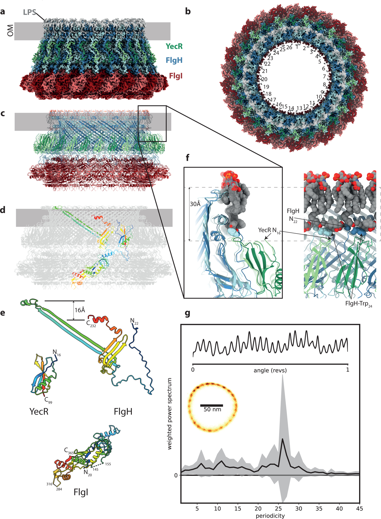
a, Side view of the 2.2 Å experimental cryo-EM volume for the LP ring bushing colored FlgI – red tones, FlgH – blue tones, YecR – green tones, lipopolysaccharide and lipidation on N-terminus of FlgH – grey. The approximate position of the outer membrane is indicated by the grey bar based on location of the detergent micelle at low contour levels. b, Top view of the cryo-EM volume showing the 26-fold symmetry colored as in (a). c, Cartoon representation of atomic model for LP ring colored as in (a) and (d) colored grey with the exception of a single copy of each chain which is rainbow colored from blue to red N to C terminus. e, View of each unique protein chain in the LP ring rainbow colored. f, Lipid interactions at top of LP ring assembly the two panels are related by a 90 degree rotation and show the protein in cartoon representation (colored as in (a) and the associated lipopolysaccharide and lipidated N-terminus as VDW spheres (colored C-grey, O-red, N-blue). The approximate height of a generic membrane is indicated. g, 26-fold periodicity in rotation of chimeric flagellar motors in E. coli. Left inset: 2Dhistogram of a 1 s recording of the position of a 100 nm gold nanoparticle attached to the hook of a single flagellar motor rotating at ~ 150 Hz; Top inset: corresponding kernel density distribution of the motor rotation angle. Main panel: the mean +/− S.D. (line and shading, respectively) of the weighted power spectrum of 27 distributions similar to the top inset, each from a 1–2 s recording of different cells, where the sodium motive force ranged from 54 – 187 mV and speeds ranged from ~ 2–500 Hz.
Table 1.
CryoEM data collection and Model Refinement Table
| Data collection | Dataset 1 | Dataset 2 | ||||
|---|---|---|---|---|---|---|
| Magnification | 105,000 | 105,000 | ||||
| Voltage (kV) | 300 | 300 | ||||
| Electron exposure (e-/Å2) | 59.2 | 58.5 | ||||
| Defocus range (μm) | −2.0 to −0.5 | −2.0 to −0.5 | ||||
| Pixel size (Å) | 0.832 | 0.832 | ||||
| Movies (no.) | 21, 097 | 41,170 | ||||
| Initial particle images (no.) | 496,086 | 2,767,823 | ||||
| Processing | C26 P-ring | C26 LP-ring | C1 distal rod/cap | C1 rod/cap map | C1 FliF map | C1 whole map |
| EMDB Code | 12193 | 12183 | 12190 | 12192 | 12195 | 12603 |
| Symmetry imposed | C26 | C26 | C1 | C1 | C1 | C1 |
| Final particle images (no.) | 3194 | 31643 | 29,748 | 60,497 | 60497 | 60,497 |
| Map resolution (Å) | 3.0 | 2.2 | 3.2 | 3.2 | 3.8 | 3.7 |
| FSC threshold | 0.143 | |||||
| Map resolution range (Å) | 3.0–4.6 | 2.2–3.1 | 2.9–10.0 | 2.9–10.4 | 3.0–13.7 | |
| Refinement | P-ring | LP-ring | Cap | Rod | FliF | Basal body |
| PDB Code | 7BJ2 | 7BGL | 7BHQ | 7BIN | 7BK0 | 7NVG |
| Model resolution (Å) | 2.5 | 2.0 | 3.0 | 2.7 | 3.1 | 3.7 |
| FSC threshold | 0.143 | |||||
| Model composition | ||||||
| Non-hydrogen atoms | 57536 | 126,022 | 7,402 | 81,721 | 57536 | 246311 |
| Protein residues | 7411 | 15,652 | 1,010 | 10,887 | 7411 | 32750 |
| Ligands | - | 52 | - | - | - | - |
| B-factors (Å2) | ||||||
| Protein | 120 | 64 | 95 | 75 | 120 | 184 |
| Ligand | - | 75 | - | - | - | - |
| Root-mean-square deviations | ||||||
| Bond lengths (Å) | 0.007 | 0.002 | 0.003 | 0.010 | 0.007 | 0.007 |
| Bond angles (°) | 0.85 | 0.54 | 0.50 | 0.90 | 0.85 | 0.73 |
| Validation | ||||||
| MolProbity Score | 2.15 | 2.72 | 1.81 | 2.25 | 2.15 | 2.32 |
| Poor rotamers (%) | 0 | 2 | 0 | 0 | 0 | 0.8 |
| Ramachandran plot | ||||||
| Favoured (%) | 95 | 93 | 97 | 90 | 95 | 93 |
| Allowed (%) | 5 | 7 | 3 | 10 | 5 | 7 |
| Disallowed (%) | 0 | 0 | 0 | 0 | 0 | 0 |
| Model v. Data CC (mask) | 0.82 | 0.86 | 0.56 | 0.85 | 0.82 | 0.72 |
The high resolution of the LP-ring map reveals details of the interactions of the bushing complex with the OM. Associated with the top most helix of each copy of FlgH is a density that corresponds to the Lipid A portion of the LPS (Fig. 1f), with extensive hydrophobic and charged interactions anchoring it in place in the outer leaflet of the OM. Densities are also observed for the 3 lipid moieties of the N-terminal Cys, with the diacylglycerol attached to the sidechain running laterally around the structure and packing against hydrophobic residues of the FlgH (Extended Data Fig. 2). Together the LPS layer and lipidation form a hydrophobic band around the L-ring that is thinner than a canonical bilayer. An additional layer of protein density was also observed outside of the L-ring, corresponding to a single domain protein bound to each FlgH. Proteomic analysis (Supplementary Dataset 1) and density-based sequencing identified this protein as YecR, a lipidated OM protein known to be regulated by the flagellar master regulator15. The position of the N-terminal Cys in YecR is more consistent with the height of a canonical membrane bilayer (Fig. 1f), suggesting it may facilitate assembly by regulating remodeling of lipids around the unusual L-ring structure, though analysis of a yecR mutant strain suggests this function is not essential (Supplementary Fig. 1).
The LP-ring is the only flagellar component observed to have 26-fold symmetry, and therefore must be responsible for the 26 steps observed in partially de-energized or damaged flagella rotation16, or fully energized, undamaged flagellar motors (Fig. 1g). The original hypothesis that steps correspond to dynamic torque-generating interactions between stator and C-ring is inconsistent with both the 34-fold symmetry of the C-ring17–19 and the observation that the phase of the 26-fold symmetry component does not change with discrete speed changes (Extended Data Fig. 3, Supplementary Fig. 2,3), a signature of structural dynamics in the stator20. Instead, the steps indicate a static 26-fold interaction potential in the bearing between the rod and LP-ring16,21.
The high-resolution LP-ring structure was subsequently used to refine the full basal body without symmetry imposed. This produced a 3.7 Å C1 map with clear density for the entire axial rod down to the export gate. Focused refinement of the rod produced a 3.2 Å map that permitted docking and re-modeling of the export gate and de novo building of all rod components (Fig. 2a,b). As previously observed in the related Type III Secretion injectisomes, the periplasmic end of the export gate flexes open relative to its isolated structure in order to nucleate the helical rod (Fig. 2c)22. Despite no detectable sequence identity, FliE is observed to be a direct structural homologue of SctI, with the C-terminal helix packing into the export gate template and the preceding helix folding back to pack into the crenelations of the FliP (Extended Data Fig. 4). Like the SctI sub-structure, the first copy of the FliE is only ordered in the C-terminal helix, with the N-terminus of FliR taking the space the other helix would occupy (Fig. 2d, Extended Data Fig. 4). From this point, the flagellar structure diverges from the injectisome, with sequential helical addition of 5 copies of FlgB, 6 copies of FlgC, 5 copies of FlgF and 24 copies of FlgG (Fig. 2d). The rod subunits are all built from the same core unit, whereby a C-terminal helix packs into the centre of the growing filament, with an N-terminal helix decorating the outside (Extended Data Fig. 4). However, the stretches of sequence inserted between the core helices show a high degree of structural variation between the different rod proteins. FlgG is observed in 3 main conformational states that build up in sequential layers, with the differences mainly in the loop following the N-terminal helix (the L-stretch) (Fig. 2d). The packing of the rod components follow the non-integer helical symmetry of the hook and filament (5.5 subunits/turn) using alternating 5:6 subunit stoichiometries. The rod helical lattice is nucleated by the organization of the export gate, with five copies of FliP each seeding two rod/hook/filament protofilaments and FliR seeding the final filament (Extended Data Fig. 5).
Figure 2. The structure of the in situ flagellar axial rod.
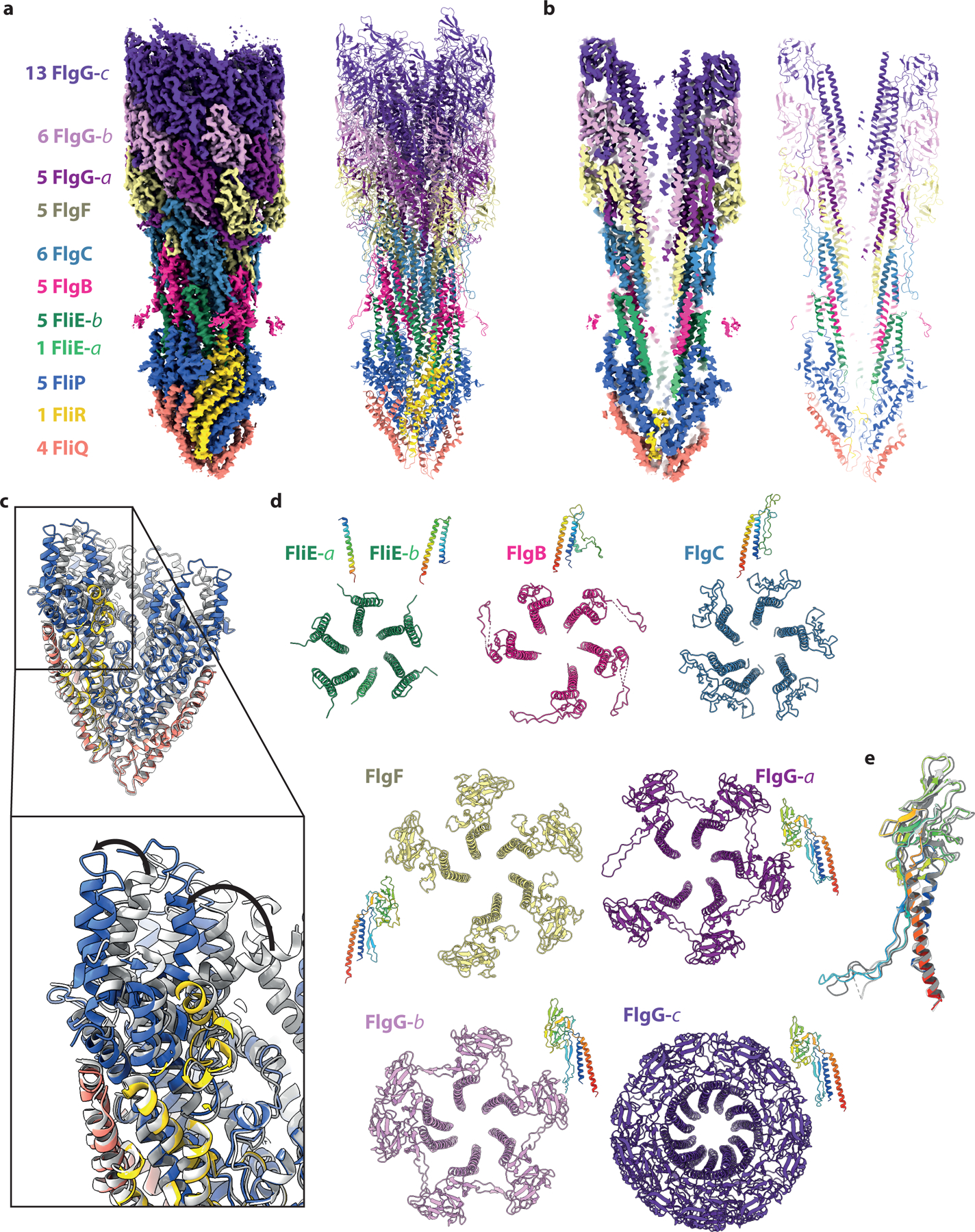
a, and b, show the experimental cryo-EM volume (left hand side) and cartoon representation of the atomic model for the rod (right hand side) colored as defined by the key in (a). The numbers in the key indicate how many copies of each unique protein chain are observed and the -a,-b,-c postscripts indicate different conformational states of the same protein chain. The panels in (b) are a cut-through of the structure to show the central channel. c, The structure of the export gate as seen in the full assembly (colored as in (a)) overlaid on the structure of the isolated export gate (grey, PDB 6r69). d, Top views of the assemblies formed by each chain / unique conformational state of each chain are shown in cartoon representations colored as in (a) with a side view of a single subunit rainbow colored. e, Overlay of the three distinct conformations seen for the FlgG subunits with FlgG-a rainbow colored and FlgG-b and -c in grey.
We next analyzed contacts between the rod and the various circularly symmetric sub-structures in the basal body (Fig. 3). The LP-ring forms a bearing for the rod, with a thin, tight seal around residues 48–82 of FlgI (Fig. 3a, green boxes in Extended Data Fig. 6a). Opposing charges on the LP-ring seal and the rod may help to hold the bearing together (green box in Extended Data Fig. 6b), while the relatively smooth outer surface of the rod and its non-commensurate symmetry with the LP-ring allow free rotation and perhaps some degree of axial sliding. Evidence for the potential for axial sliding comes from a 3.0 Å structure of the P-ring in the absence of the L-ring (Extended Data Fig. 7), where the FlgI assembly is seen to be positioned around the lowest tier of the distal rod, closer to the MS-ring than in the final assembly. This structure is consistent with earlier studies of the roles of the rod in LP-ring assembly stages23–25. While the mismatched symmetries of the P-ring and the rod act to minimize friction in the bearing, the C1 structure is capable of producing the 26-fold interaction potential (Fig. 1g). For example, Glu203 on sequential 1-start helix copies of FlgG has the potential to form salt bridges with Lys82 and Lys114 on two copies of FlgI, providing a local barrier to rotation on one side of the bearing. Once the torque overcomes this barrier, new salt bridges involving the same FlgG residues could form with the next set of FlgI subunits after a 13.8° rotation.
Figure 3. Interactions of the rod and export gate with the OM and IM ring structures.
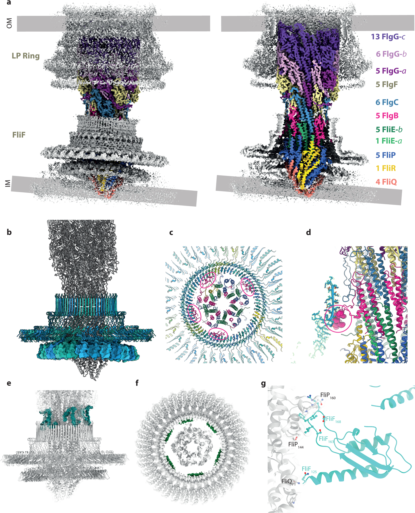
a, Overview of the C1 volume obtained by focusing alignments on the axial rod components. The volume is colored grey with the exception of the rod components which are colored as in Figure 2(a) on right hand panel shows a cutaway of the left hand panel. The mis-alignment of components in the inner and outer membranes is clear in this view. b, Cartoon of the assembly focusing on the inner membrane components with the 34mer FliF colored in blue shades. The 34-fold RBM3 ring of FliF (blue shade cartoon) is set horizontally revealing the distortion of the 23-mer RBM2 ring (surface representation), presumably driven by contacts between the circular RBM2 oligomer and the helical export gate. Other contacts between FliF and the axial components are shown by coloring the experimental volume according to the putative component contributing the contact. c and d, Interaction between FlgB and the inside of the FliF RBM3/ß-collar. e, Putative FliF loop (teal) reaching around top of FliF assembly to contact axial rod at level of the FlgB/FlgC/FlgF interfaces. f, Putative FliE helix (pink) contacting base of RBM3 ß-collar. g, Close up of contacts between one copy FliF RBM2 and the export gate, coloured as in (b).
At the proximal rod end there are myriad contacts between different chains of the rod/export gate and the MS-ring, consistent with the idea that the rod must be stably attached to the rapidly rotating motor. Focused refinements around the MS-ring revealed key details in these regions. Firstly, the FliF is observed to be a 34-mer, with the RBM3/β-collar region displaying true C34 symmetry (Fig. 3b). Contacts in this region extend in both directions, with FliF interdigitating between rod subunits, and rod subunits packing against the inside of the MS-ring β-collar (Fig. 3c,d,e,f). While the FliF densities are not sufficiently connected to unambiguously assign sequence, they clearly extend from the top of the β-collar and slot into gaps between FlgB, FlgC and FlgF, with flexibility allowing different heights to be reached in the helix (Fig. 3e). A long insertion in the FlgB (residues 58–82) packs against the midpoint of the FliF β-collar, with an interaction involving strongly co-varying residues including His72 on FlgB and Asn365 on FliF (Fig. 3c,d). Flexibility in the linkers of the insertion allow the FlgB to pack with circular symmetry despite the helical symmetry of the FlgB core. There is also a further layer of contacts at the base of the β-collar (Fig. 3f) that likely correspond to the predicted N-terminal helices of FliE, but sequence cannot be assigned in the current density. These layers of interactions between the rod and the MS-ring, that presumably exist to increase the structural stability of a rotating unit, may explain the increased complexity of composition of the rod compared to the equivalent region of the injectisome; new rod subunits structures being required at each turn of the filament in order to bind to a different layer of the MS-ring. Finally, the export gate packs in the RBM2inner ring of the MS-ring. The RBM2inner ring is observed to contain 23 copies of RBM2, in contrast to the 22 copies observed in the isolated 34-fold MS-ring. This is analogous to equivalent region in the injectisome, where isolated structures lacking export gate contain one fewer copy of the SctJ protein26. The RBM2inner ring does not follow the circular symmetry of the RBM3/β-collar, instead molding itself around the helical export gate to form a highly distorted ring (Fig. 3b). The loop (residues 158–173) that binds the export gate also displays plasticity to accommodate the different portions of structure it packs against (Fig. 3g). No evidence is seen for the FlhB component of the export gate, but this has previously been shown to be sensitive to the detergents used in extraction27,28. It is also possible that the detergent/lysozyme extraction process, and removal of the constraints imposed by the two membranes, has led to the observed non-coaxial relationship between the rod and the MS-ring.
The basal bodies characterized here stall after rod completion. The next stage in flagellar assembly would be construction of the hook, a process that is proposed to be catalyzed by the hook capping protein, FlgD29. Analysis of the end of our rod map revealed clear helical densities in the center of the completed rod that were not consistent with extra rod subunits, and FlgD protein was identified in the sample (Supplementary Dataset 1). Further classification and focused refinement of the distal end of the rod resolved this region into five helical hairpins with clear sidechain density (local resolution of 2.9 Å) connected to a lower resolution (local resolution of > 7 Å) pentameric structure (Extended Data Fig. 8). De novo building of the helices, and docking of a crystal structure of FlgD (PDB, 6iee) into the lower resolution density, allowed us to construct a model for a full-length pentameric FlgD cap (Fig 4a,b,c), though care must be taken not to interpret features in the C-terminal domains beyond those already observed in the crystal structure. Residues 30–70 of FlgD are seen to form a helical hairpin (Fig. 4a), a previously unpredicted feature, though consistent with co-evolution data (Extended Data Fig. 8d). The more N-terminal helix runs down into the rod structure and mimics the positioning and orientation of a rod subunit, before bending back so the second helix of the hairpin can assemble into a 5 helix bundle with the other 4 copies (Fig. 4b). Overlay of the 5 monomers reveals a remarkable amount of flexibility in the structure (Fig. 4d), with different degrees of hinging between the 2 helices to accommodate linking the circularly symmetric C-terminal domain structure with the hairpins that follow the helical rise of the rod.
Figure 4. The structure of the in situ hook cap complex (FlgD).
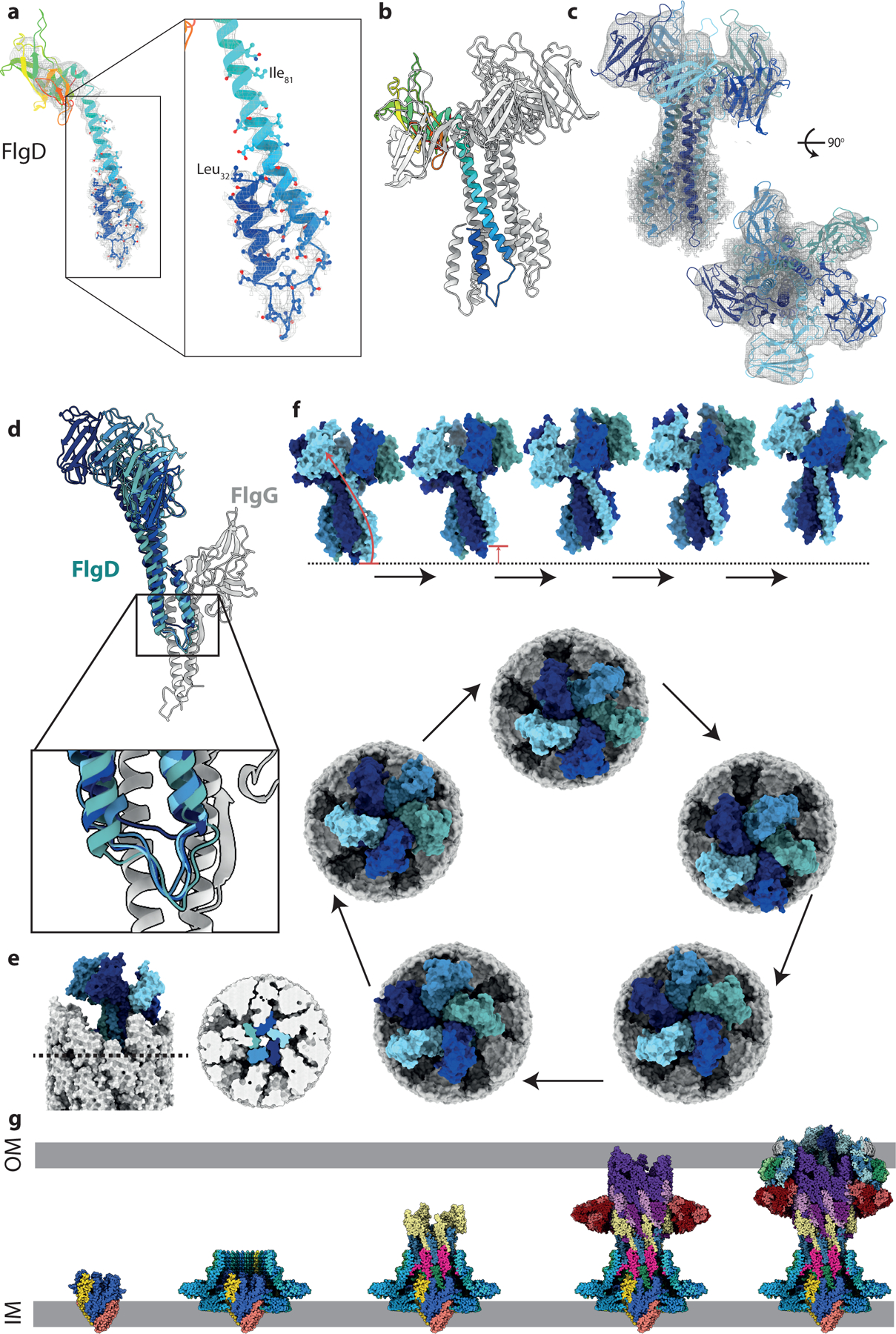
a, The N-terminus of FlgD, the hook cap protein forms an unexpected bent-back helical pair. b, Pentamer of FlgD, with one copy represented as a rainbow. c, FlgD pentamer, colored by chain, shown in the experimental local resolution volume (grey mesh). (d) Overlay of five FlgD (blue) – FlgG (grey) pairs showing the main interface. One copy of FlgD (navy blue) sits particularly high against its cognate FlgG, showing the FlgD helices can slip vertically with respect to FlgG. e, Surface representation of the tip of the axial components with the cap in situ shows that the top sits at an angle to the rod axis. Right hand panel shows a cut-through at the level indicated in the left-hand panel allowing visualisation of the tight packing of the FlgD blades created by the paired helices at the N-terminus. (f) Proposed motions involved in FlgD cap catalysed assembly mechanism. Top panel (Supplementary Movie 1) show a side view of four sequential cap movements orientated as in part (e), with the rod removed for clarity. In the first transition, the movement of the lowest copy (light blue) to become the highest copy is illustrated with an arrow. The bottom panel shows a top down view of the cap on the rod, showing a full revolution of the cap around the rod, sequentially opening up rod/hook subunit binding sites, without any rotation of the cap structure on its axis. (g) Assembly steps of the flagellar basal body shown using the sub-structure solved in this study. Export gate nucleates correct assembly of the MS-ring and seeds the protofilaments of the rod. Rod growth to the point of FlgG allows assembly of the P-ring around the IM-proximal end of the distal rod, which can then act as an assembly point for the L-ring. OM-tethering of FlgH places the LP-ring at an appropriate height on the distal rod. Finally, FlgD assembly on the tip of the distal rod permits correct insertion of hook subunits via stepped revolution.
Analysis of the in situ cap structure provides key insights into the mechanism of cap function and filament assembly. The “resting” cap structure observed here completely blocks exit points from the rod filament, requiring structural rearrangement to allow secretion of the next component (Fig 4e). Previous models of filament cap function have invoked rotation of the cap structures to open up the next filament subunit binding site30,31. Our structure reveals that the helical hairpins are tucked deep enough into the rod interfaces to sterically prevent such a rotation (Fig. 4e). It is notable that the lowest monomer in the pentamer, which is the one facing the space for a new filament subunit, does not completely follow the helical pitch, but is sitting high as if primed for an insertion event (Fig. 4d). We therefore propose that emergence of a new hook subunit pushes this copy of FlgD upwards to allow secretion (Fig. 4f). Correct insertion of the anchoring helix of a hook subunit would allow this copy of FlgD to click into place in a new position at the top of the pentamer, reorienting the C-terminal domains in such a way that the next FlgD hairpin is primed for the insertion event (Fig. 4f, Supplementary Movie 1). When repeated, this mechanism leads to a “stepped revolution” of the cap on the top of the growing filament (Fig. 4f). Failure to insert, either by chance or due to lack of appropriate sequence on the anchoring helix of the secreting subunit, would likely lead to a reset of the position of the first FlgD.
In summary, our flagellar basal body structures provide a sub 3 Å structure of the OM LP-ring, detailed views of the entire flagellar rod and hook cap complex, and insight into the ordered assembly processes of this immensely complex molecular machine (Fig 4g).
Methods
Materials
All chemicals were obtained from Sigma-Aldrich unless otherwise stated.
Bacterial strains
Basal bodies were purified from S. Typhimurium strain TH25631 (ΔflgE7659 flhD8070 flhC8092 fliA5225 ΔfliB-T7771 fliG8835(ΔPAA) ΔrflM8403 fljBenx vh2), which expresses elevated numbers of hook-basal body structures per cell due to elevated FlhDC levels32. The flhD8070(L22H) and flhC8092(Q29P) were isolated as resistant to ClpXP protease degradation33,34. The rflM gene encodes a repressor of flhDC transcription35, and was deleted by recombineering using the tetRA cassette replacement method as described36. The fliG8835 allele has a three amino acid deletion (Pro169-Ala170-Ala171) and is an extreme clockwise rotation mutant of the flagellar rotor37. The fliG8835 3-amino acid deletion allele was constructed in TH25631 by first replacing the Pro169-Ala170-Ala171 region of fliG with a tetRA cassette followed by replacement of the tetRA cassette by oligonucleotide targeted replacement of the tetRA cassette that leaves the 3-amino acid deletion as described36. The strain TH26465 (ΔyecR::tetRA) was generated by recombineering.
E. coli strain YS34 (ΔCheY, fliC::Tn10, ΔpilA, ΔmotAmotB), transformed with plasmid pYS13 (pomApotB38, IPTG inducible, chloramphenicol resistance, pMMB206 derivative), was used for gold nanoparticle motor tracking experiments. These cells were grown from frozen aliquots in 5 ml of tryptone broth (1 % (w/v) Bacto tryptone (Difco), 0.5 % (w/v) NaCl) at 30°C with appropriate antibiotics and inducers (chloramphenicol, 25 μg/ml, IPTG, 30 μM) for 4.5–5.5 hours.
Basal body purification
The purification of basal bodies from S. Typhimurium strain TH25631 was based on protocols published previously39–41. Briefly, the strain was plated from glycerol stocks on LB agar, then colonies were picked and grown overnight at 37°C in LB medium. Eight liters of LB medium, in 2.5 L baffled shaker flasks, was inoculated with the overnight culture (4 mL/L) and then incubated at 37°C, 200 rpm until an OD600 of 0.9–1, was reached (approximately 3.5 h). Cells were harvested by centrifugation at 4,000xg for 15 min, 4°C. Cell pellets were resuspended in 160 mL of ice-cold sucrose solution (0.5 M Sucrose, 0.15 M Trizma base (unaltered pH)) and while the cell resuspension was stirred at 4°C, lysozyme and EDTA pH 4.7 were slowly added (over 5 min) to final concentrations of 0.1 mg/ml and 2 mM, respectively. After 5 min of stirring at 4°C, the resuspension was moved to room temperature and stirred slowly for 1 h to allow the formation of spheroplasts. To lyse the cells, Triton X-100 was added to a final concentration of 1% (v/v), and the solution was stirred rapidly for 10 min, until it became translucent. To completely degrade the DNA, 2 mg of DNase I and MgSO4 (5 mM final concentration) were added to the lysate. After 5 min, EDTA pH 4.7 was added to a final concentration of 5 mM. The volume of the lysate was made up to 240 mL with sucrose solution, then unlysed cells and cell debris were removed by centrifugation at 15000xg for 10 min, 4°C. Supernatant was collected and centrifuged at 142,000xg for 1 h, 4°C to collect basal bodies. Pellets were resuspended in 60 mL of resuspension buffer (0.1 M KCl, 0.3 M Sucrose, 0.1% (v/v) Triton X-100, unbuffered) and centrifuged again at 104,000xg for 1 h, 4°C. The pellet was resuspended in 2 mL of TET buffer (10 mM Tris pH 8, 5 mM EDTA pH 8, 0.1% (v/v) Triton X-100) then loaded onto 20–50% (w/w) sucrose gradients in 10 mM Tris pH 8, 5 mM EDTA pH 8, 0.03% (v/v) Triton X-100, made with a BioComp Gradient Station. Sucrose gradients were centrifuged for 14 h at 60,000xg, 4°C and then fractionated. Gradient fractions were analysed by SDS-PAGE and negative stain electron microscopy and those containing basal bodies were pooled and dialysed against 10 mM Tris pH 8, 5 mM EDTA pH 8, 0.03% (v/v) Triton X-100 in 5 mL 300 kDa molecular weight cut-off (MWCO) Float-A-Lyzer®G2 Dialysis Device (Spectrum Laboratories, Inc.) overnight. Dialysed basal bodies were then concentrated to an A280 of 1.5, using a 300 kDa MWCO Nanosep® centrifugal concentrator (PALL).
Cryo-EM sample preparation and imaging
Cryo-EM grids were prepared using a Vitrobot Mark IV system (FEI) at a temperature of 4°C and 100% humidity. Basal body samples were applied to graphene oxide coated42 Quantifoil Cu 300 mesh R 2/1 grids for 60 s before being blotted for 3 s, force −5 and then plunged into liquid ethane. Data were collected in counted super-resolution mode on a Titan Krios G3 (FEI) operating at 300 kV with a BioQuantum imaging filter (Gatan) and K3 direct detection camera (Gatan) using a physical pixel size of 0.832 Å. An initial 21,102 movies were collected at a dose rate of 15.4 e-/pix/s and exposure of 2.66 s, corresponding to a total dose of 59.2 e-/Å2, followed by collection of an additional 41,178 movies at dose rate of 14.5 e-/pix/s, exposure of 2.80 s, and total dose of 58.5 e-/Å2. All movies (62,280 total) were collected over 40 fractions.
Cryo-EM data processing
Micrographs were initially processed in real time using the SIMPLE pipeline43, using SIMPLE-unblur for motion correction, SIMPLE-CTFFIND for CTF estimation and SIMPLE-picker for particle picking. Following initial 2D classification in SIMPLE to remove poor quality particles, all subsequent processing was carried out in in RELION-3.144. 43843 particles from the first dataset were re-extracted and subjected to further 2D classification. C-ring occupancy of the extracted basal bodies was observed to be variable, so selected particles (27214) were re-extracted in 432 × 432 pixel boxes centered on the LP-ring. Following another round of 2D classification, the most intact 18041 particles were refined in a variety of symmetries using an initial model generated from class averages. Only C26 symmetry produced maps with sidechain detail. The particles were subjected to two rounds of CTF refinement and one round of Bayesian polishing45, following which 3D classification produced a class with 10898 particles that refined to 2.2 Å resolution map using gold standard refinement. The second dataset produced 155747 particles after SIMPLE 2D, and these were re-extracted in RELION3.1 and subjected to 2D classification followed by re-extraction in LP-centered 432 × 432 pixel boxes. Combination with the first dataset and further 2D classification produced a 10237 particle subset which clearly lack the L-ring. These were refined with C26 symmetry from an LP-ring initial model low pass filtered to 15 Å resolution. A single round of 3D classification produced a set of 3194 particles that refined to a 3.0 Å resolution map using gold standard refinement.
The second dataset was also selected for intact LP-ring particles, producing 54766 particles that were combined refined and subjected to CTF refinement. These particles were then combined with the 27214 particles from the first dataset. This combined particle set was re-extracted in a 768 × 768 pixel box and subjected to 2D classification, from which 71517 particles were selected. These particles were put into masked refinement in C26 with an initial model generated from the LP-ring structure and a mask around the LP-ring. The resulting refinement was used to Bayesian polish the particle set, after which refinements were attempted with no symmetry imposed (C1). Following alignment of particles with a mask around the MS-ring and proximal rod regions, a full refinement with a mask around the entire basal body produced a 3.7 Å resolution map, using gold standard refinement, with clear helical densities through the length of the whole rod. This refinement was then used as the start point for a series of C1 refinements using local searches only and masking around different portions of the structure. Refinement with a mask around the entire rod sub-structure produced a gold standard refinement with a resolution of 3.2 Å. Refinement with a mask around the LP-ring produced a gold standard refinement with a resolution of 3.6 Å. Refinement with a mask around the RBM3/collar region of the MS-ring produced gold standard refinements with resolutions of 3.5 Å in C1 and 2.8 Å in C34. Finally, two rounds of 3D classification were carried out without image alignments, using a mask around the distal rod and cap region. This produced a 29748 particle set which refined to a 3.2 Å resolution map using gold standard refinement.
Model building and refinement
Atomic models were built using Coot46, guided by co-evolution analysis. FlgH, FlgI, YecR, FliE, FlgB and FlgC models were built entirely de novo in their highest resolution maps. FlgF and FlgG were rebuilt from the crystal structure of the FlgG domain (PDB, 6jf2), with the helical portions being built de novo. The N-terminal helical regions of FlgD were built de novo and the C-terminal domain structure docked as a rigid pentamer from a crystal structure. The RBM3/collar region of FliF was docked using a previous structure (PDB, 6sd4), while the 23 copies of RBM2 region were built using the monomer structure from an earlier 22mer structure (PDB, 6sd5). The previously determined FliPQR structure (PDB, 6r69) was docked and manipulated to fit the density. Multiple rounds of rebuilding (in both globally sharpened and local-resolution filtered maps) and real-space refinement in Phenix47 using secondary structure, rotamer and Ramachandran restraints yielded the final models described in Table 1. All models were validated using Molprobity48. Figures were prepared using UCSF ChimeraX49 and Pymol (The PyMOL Molecular Graphics System, Version 2.0 Schrödinger, LLC).
Sample preparation for mass-spectrometry analysis
A sample of purified basal bodies was run briefly into a 4–20% Mini-PROTEAN® TGX Stain-Free™ gel (BIO-RAD), which was then stained with InstantBlue™ before the gel section containing the sample was excised and sent for analysis at either the BSRC Mass Spectrometry Facility (University of St Andrews), or the Advanced Proteomics Facility (Department of Biochemistry, University of Oxford).
Evolutionary co-variance analysis
Co-evolutionary contacts were determined by the Gremlin web-server50. Searches used the HHblis or Jackhmmer algorithms for multiple sequence alignment, an E-value threshold of 10−6 and a minimum coverage of 75%. Co-variance was assessed between FlgH (2683 sequences) and FlgI (2340 sequences), FlgD (1120 sequences) and FlgG (3990 sequences), FlgG (3973 sequences) and FlgF (2953 sequences), FlgF (2953 sequences) and FlgC (1248 sequences), FlgC (1248 sequences) and FlgB (1668 sequences), FlgB (1668 sequences) and FliE (919 sequences), FlgC (1248 sequences) and FliF (1365 sequences), FlgB (1668 sequences) and FliF (1365 sequences), FlgB (1668 sequences) and FliP (1367), FliE (919 sequences) and FliP (1367 sequences). All inter-subunit contacts with an I_prob value > 0.75 were assessed during model building. Intra-subunit contacts with a prob score > 0.75 were assessed when building monomer models de novo.
Motor rotation measurements
Cells were immobilised on poly-L-lysine coated glass coverslips in custom-made flow chambers. Goat anti-rabbit IgG was conjugated to gold nanoparticles as described previously51: Goat anti-rabbit IgG (Sigma-Aldrich R5506) was activated with LC-SPDP4 (Pierce, 21651) according to the manufacturer’s instructions. 2.5 uL was then added to 500uL of 100nm gold beads (British Biocell International, EM.GC100) and left to incubate for 2 hours at room temperature. 10u L of mPEG-SH 5000 (Sigma-Aldrich, 81323) was added and incubated at room temperature overnight. Rabbit anti-FlgE antibody51 (gift from Howard Berg, University of Harvard) was purified using an IgG purication kit (Dojin-Do, kit A; 0.1 mg/mL measured via the Bradford Method). A mixture of 2.5 uL of antibody and 100 uL of washed cells was incubated for 25 minutes on a tabletop spinner, then washed twice and resuspended in 40 L of MB. 100 uL of IgG gold particles was washed once, resuspended in the antibody treated cells, incubated for 25 minutes at on a tabletop spinner, then washed and resuspended in 300 uL of MB. Beads were tracked using back-scattering dark-field microscopy (see below) and a CMOS camera (Photron). The acquisition rate was 109.5 kHz. Experiments were performed in motility buffer (10 mM potassium phosphate, 0.1 mM EDTA, 1–85 mM potassium chloride, pH 5.0 – 7.0) at 23°C.
Laser back-scattering darkfield microscopy
A mirror with a 1 mm hole in the center was mounted at a 45% angle as near the objective back focal plane (BFP) as possible (M2 in Extended Data Fig. 3a). Light from a 633 nm HeNa laser (Melles Griot LHX1, 10mW) passed through the hole and was focused onto the BFP of the objective (Nikon Plain Flour 100x oil, NA 1.3–1.4). The diameter of the field of view was ~ 1 μm. The back-scattered light was collected by the objective, and reflected to the imaging pathway by the mirror with the hole and imaged onto the CMOS camera. A high-power LED (Thorlabs 617L2) and condenser (Nikon 1.4NA) allowed for brightfield imaging. This back-scattering setup was inspired by Sowa et al52, though the use of a mirror with a hole instead of a rod mirror allows for less than 4% loss of back-scattered light, compared to 8%. Recordings of gold beads stuck to a coverslip (not shown) show the total noise of the system, measured in a 55kHz bandwidth to be less than 1 nm2. For a typical BFM measurement, this corresponds to an angular resolution of better than 1° with a time resolution of 9.1 μs.
Angular measurements
BFM rotation analysis was performed with custom MATLAB and Python programs. The position of the bead was determined using a Gaussian Mask fitting algorithm53. An ellipse was fit to the (x,y) position of the bead54, the data was transformed to a circle and the angular position of the motor was determined. Speed was calculated as the change in angular position between each frame multiplied by the frame rate.
A gaussian kernel of 0.02 rad was used to the create kernel density plots of the angular position shown in Fig 1g and Extended Data Fig. 3f. Histograms of the angular position (1.5-degree bin width) were used to calculate the power spectral density, which was then multiplied by the periodicity to give the weighted power spectrums shown in Fig 1g and Extended Data Fig. 3g.
Extended Data
Extended Data Fig. 1. Cryo-EM analyses of intact flagellar basal bodies.
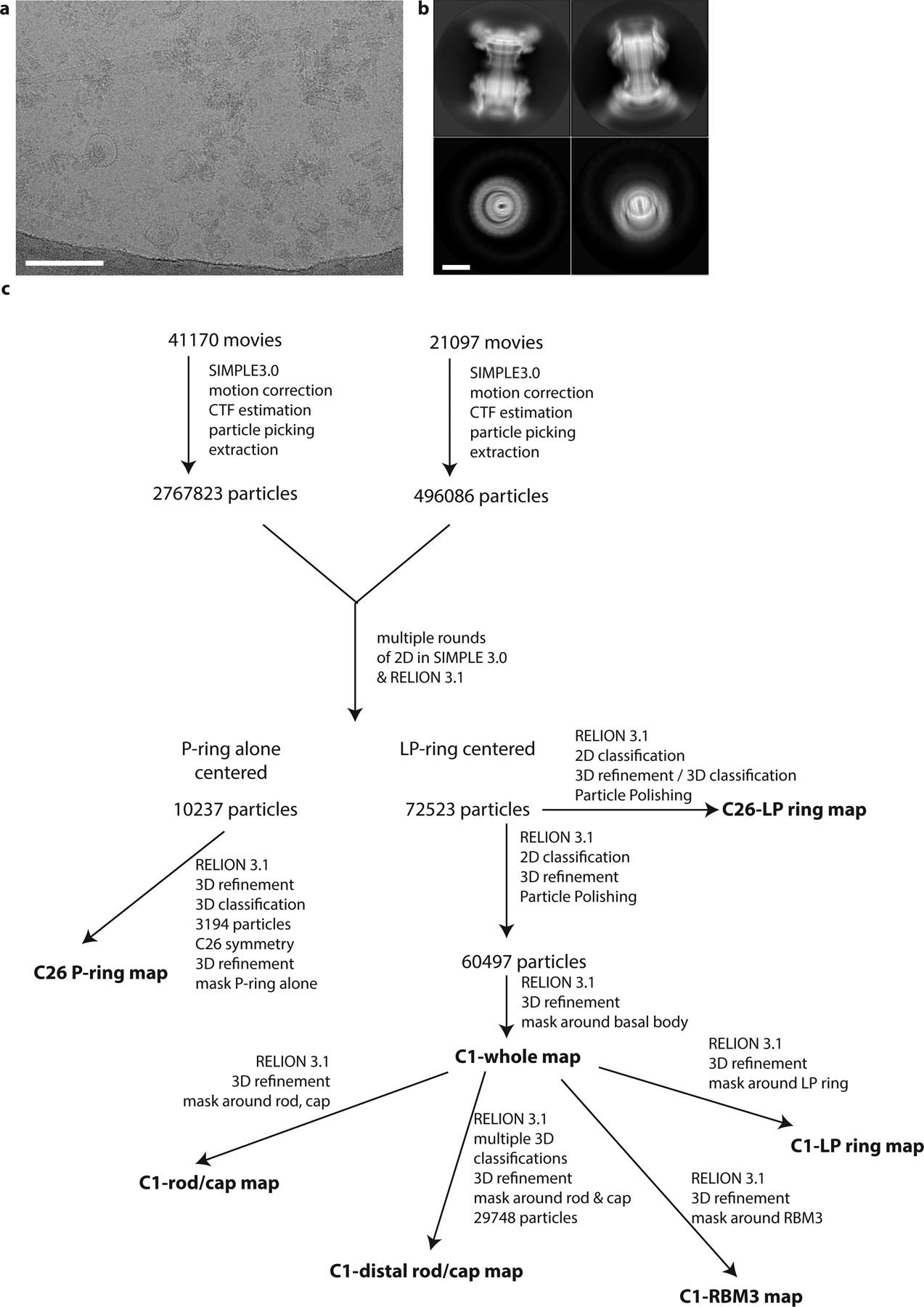
a, Example micrograph of Salmonella enterica serovar Typhimurium basal bodies on a graphene oxide surface. Scale bar 200Å. b, 2D class averages of basal bodies. Scale bar 100Å. c, Simplified workflow to show key stages in generation of each volume.
Extended Data Fig. 2. Structure of the LP-ring.
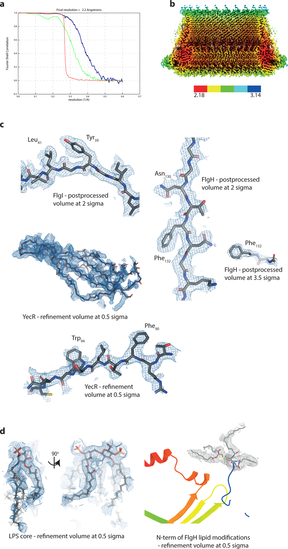
a, Gold-standard Fourier shell correlation (FSC) curve of RELION-postprocessed LP-ring C26 map. Resolution at the gold-standard cut-off (FSC = 0.143) is indicated. Curves: red, phase-randomized; green, unmasked; blue, masked; black, corrected. b, Local resolution estimates (in Å, as calculated by RELION3.1 LocalRes. c, Representative modelled densities of the three protein chains. d, Representative modelled densities of the lipid moieties.
Extended Data Fig. 3. Rotation periodicity in flagellar motors.
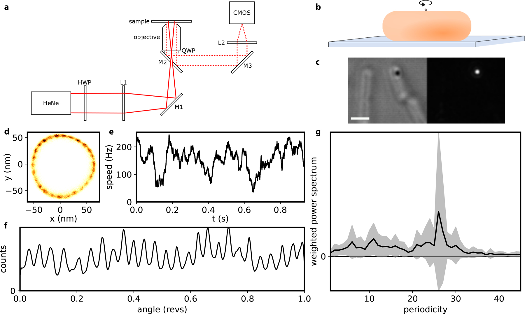
a, Backscattering dark field setup. (M: mirror; L: lens; HWP: half wave plate; QWP: quarter wave plot; HeNe laser; fast CMOS camera). b, Schematic of the experimental assay: a gold nanoparticle of 100 nm is attached to the hook of a BFM on a surface-immobilised cell. c, Brightfield (left) and darkfield (right) image of a nanoparticle attached to the hook of a bacterial cell (scale bar is 1um). d-f, An example recording showing the 2D histogram of the position of the rotating nanoparticle, with 26-fold periodicity in rotation (d); the angular speed of the motor (median filtered, 20 ms window) (e); the kernel density distribution of the angular position of the motor (f). g, The average +/− S.D. (line and shading, respectively) of the weighted power spectrum of a histogram of the angular position. (27 motors recorded for 1–2 s, each from a different cell, where the sodium motive force ranged from 54 – 187 mV and speeds ranged from 2 – 300 Hz.). See Methods for details.
Extended Data Fig. 4. Structure of the intact flagellar rod.
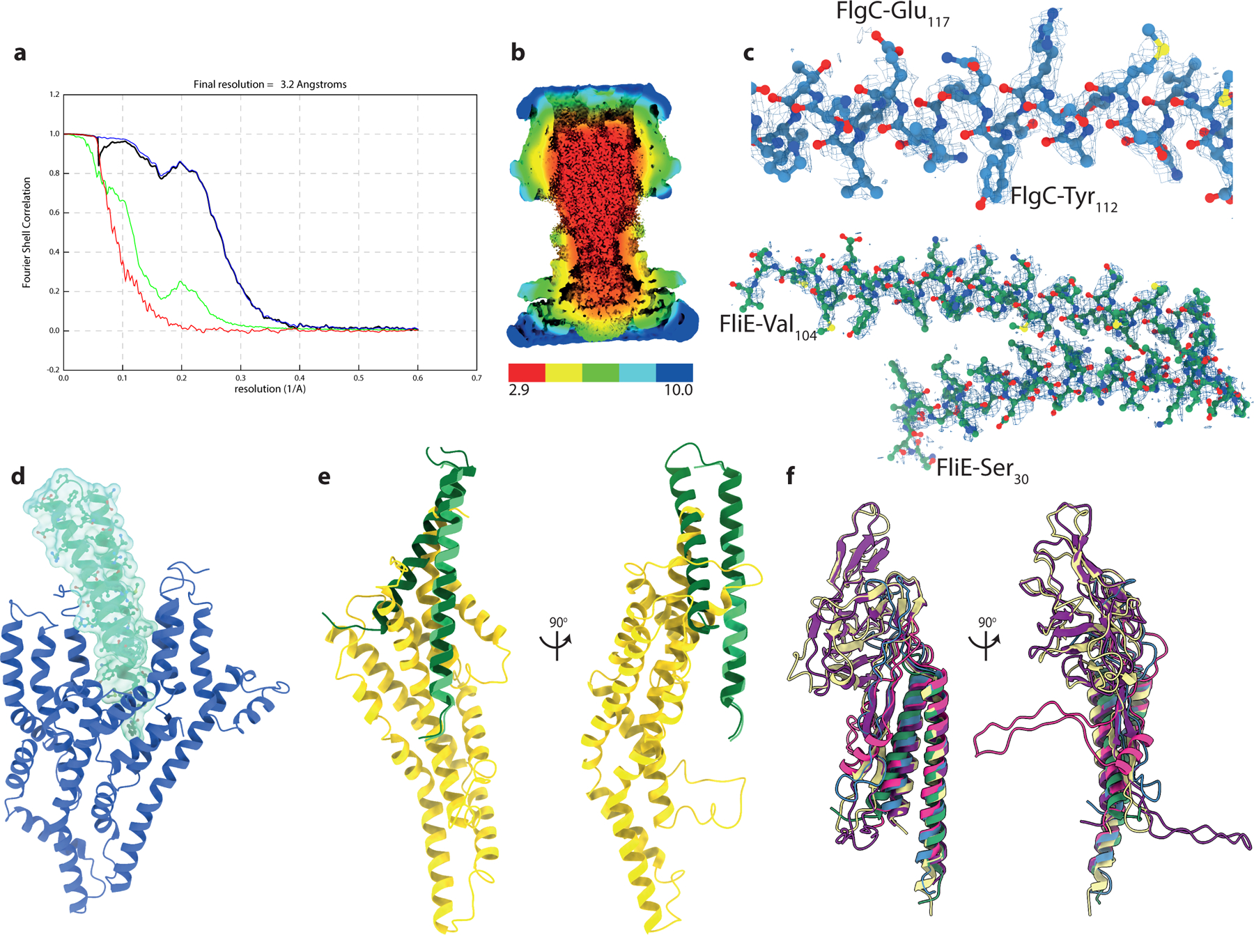
a, Gold-standard Fourier shell correlation (FSC) curve of RELION-postprocessed rod C1 map. Resolution at the gold-standard cutoff (FSC = 0.143) is indicated. Curves: red, phase-randomized; green, unmasked; blue, masked; black, corrected. b, Local resolution estimates (in Å), as calculated by RELION3.1 LocalRes. c, Representative modelled protein densities. d, Interaction of FliE (green cartoon and surface) with FliP of the Export Gate (blue cartoon). e, Overlay of a full FliE subunit (FliE-b) with FliE-a, demonstrating the overlap with the position of the FliR N-terminus. f, Overlay of representative rod subunits demonstrates the conserved core and variation in inserted domains (subunits colored as in Figure 2)
Extended Data Fig. 5. Analysis of the rod helical lattice.
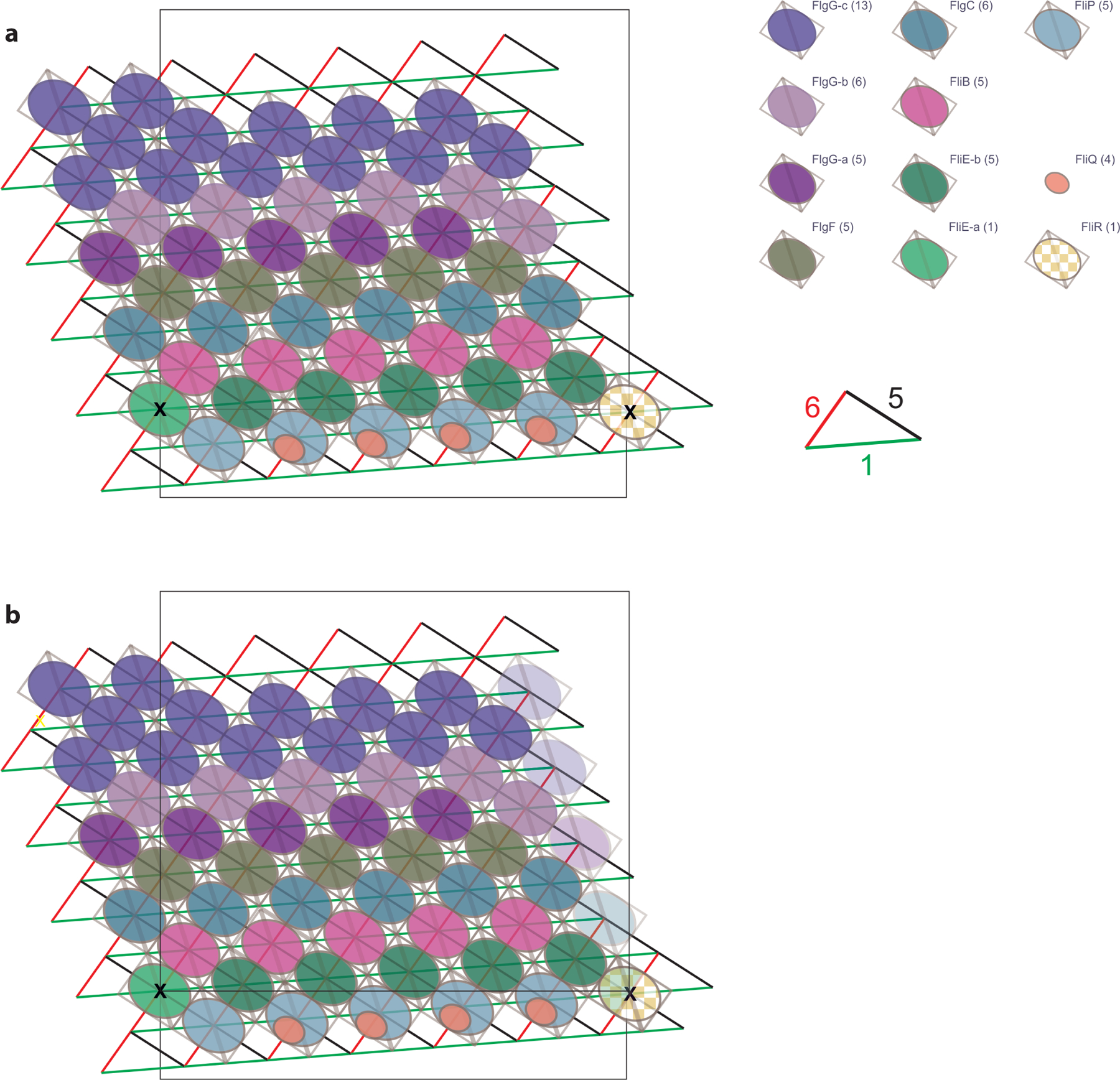
a, Representation of the helical symmetry of the rod, with the different X-start helices highlighted. Protein subunits are represented as ellipses, colored as in Figure 2. The lattice node shared by FliR and FliE-a is highlighted. b, Alternative representation of the lattice with ‘ghost’ additional protofilament to show how the structure closes.
Extended Data Fig. 6. Structure of the LP-rod bearing.
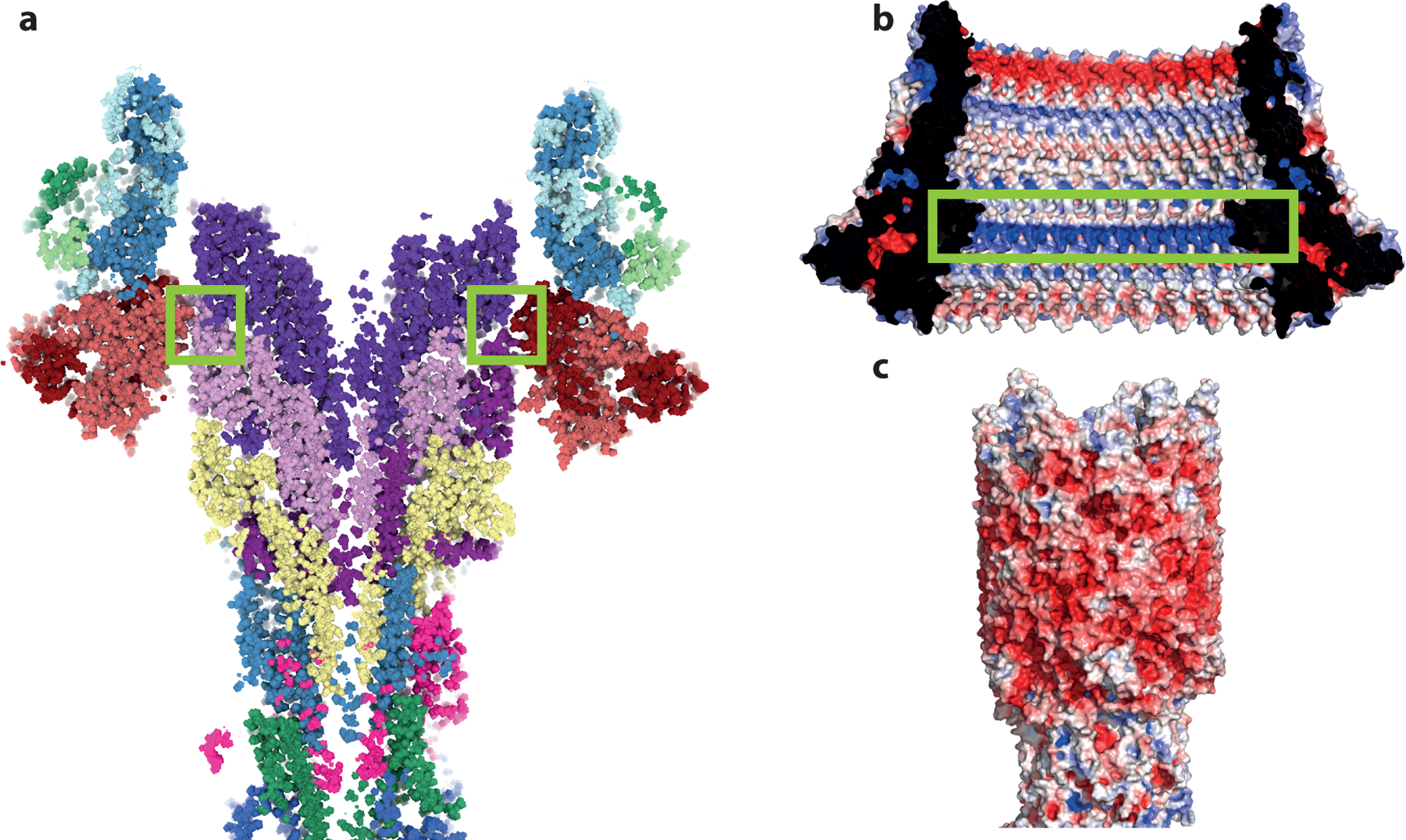
a, Slab through the LP-rod demonstrating the thin seal around the rod. Green boxes highlight the constriction point formed by residues 48–82 of FlgI. b, Electrostatic potential mapped onto the surface of the LP-ring (view from inside the ring) with the positively charged band at the seal point highlighted in a green box). c, Electrostatic potential mapped onto the surface of the rod. Electrostatics analysed using APBS within Pymol.
Extended Data Fig. 7. Structure of the P-ring in the absence of the L-ring.
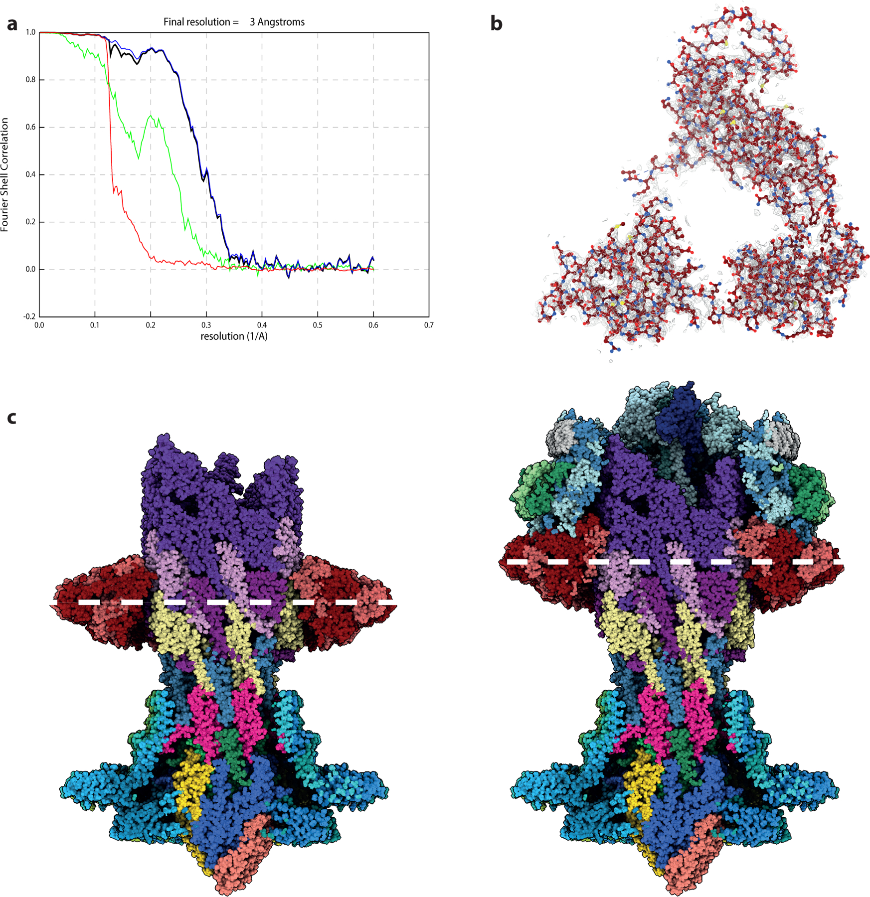
a, Gold-standard Fourier shell correlation (FSC) curves of RELION-postprocessed P-ring C26 map. Resolution at the gold-standard cut-off (FSC = 0.143) is indicated. Curves: red, phase-randomized; green, unmasked; blue, masked; black, corrected. b, Volume (silver mesh) contoured at 0.018 electrons/Angstrom over one copy of FlgI (shown as ball-and-stick representation) c, Side by side views of the cutaway P-ring structure next to the intact basal body, aligned on the collar of the MS-ring/rod. The white dashed line highlights the centre of the P-ring assembly.
Extended Data Fig. 8. Structure of the flagellar hook cap assembly.
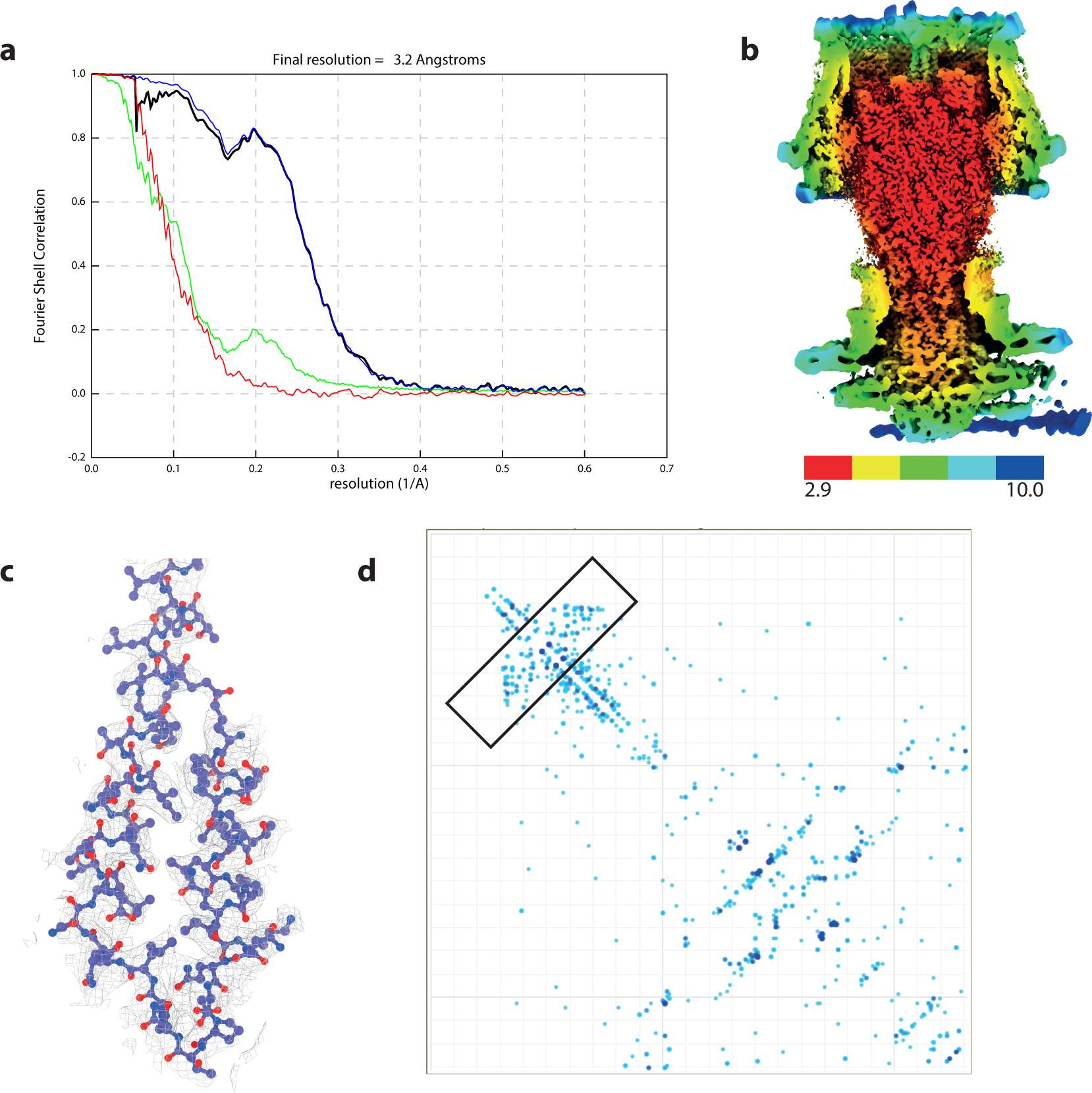
a, Gold-standard Fourier shell correlation (FSC) curve of RELION-postprocessed rod C1 cap map. Resolution at the gold-standard cutoff (FSC = 0.143) is indicated. Curves: red, phase-randomized; green, unmasked; blue, masked; black, corrected. b, Local resolution estimates (in Å), as calculated by RELION3.1 LocalRes. c, Representative modelled protein densities. d, Two-dimensional residue plot of FlgD showing co-variance between residue pairs, as calculated by Gremlin. Stronger co-variance is highlighted by darker colours. The N-terminal hairpin region is highlighted with a box.
Supplementary Material
Proposed motions involved in FlgD cap catalysed assembly mechanism. The cap is shown as a surface, colored as in Figure 4c. The movie (and Figure 4f) shows a side view of sequential cap movements orientated as in Figure 4e with the bacterial membranes below.
The proteomic identifications based on extraction from gel as described in the methods.
Zip file containing python directory with full source data and python script used to analyse data and generate plots shown in Fig. 1g, Extended Data Fig. 3, Supplementary Figures 2–3
Acknowledgments:
We thank Errin Johnson and Adam Costin of the Central Oxford Structural Molecular Imaging Centre (COSMIC) for assistance with data collection; Hans Elmlund (Monash) for access to SIMPLE code ahead of release; Nigel Moriarty, Paul Emsley and Garib Murshudov for help with modelling lipid ligands. We acknowledge use of the University of St Andrews BSRC Mass Spectrometry facility, and the Advanced Proteomics Facility of the Department of Biochemistry, University of Oxford, including Marjorie Fournier for data processing.
Funding:
The Central Oxford Structural Molecular Imaging Centre is supported by the Wellcome Trust (#201536), The EPA Cephalosporin Trust, The Wolfson Foundation and a Royal Society/Wolfson Foundation Laboratory Refurbishment Grant (#WL160052). Research in S.M.L.’s laboratory is supported by Wellcome Trust Investigator (#219477) and Collaborative awards (#209194) and an MRC Programme Grant (#S021264). ALN is a member of the CBS which is part of the France-BioImaging (FBI) and the French Infrastructure for Integrated Structural Biology (FRISBI), two national infrastructures supported by the French National Research Agency (#ANR-10-INBS-04-01 and #ANR-10-INBS-05, respectively).
Footnotes
Competing interests: Authors declare no competing interests.
Data Availability Statement
Cryo-EM volumes and atomic models have been deposited to the EMDB (accession codes EMD-12183, EMD-12190, EMD-12192, EMD-12193, EMD-12195) and PDB (accession codes 7BGL, 7BHQ, 7BIN, 7BJ2 and 7BK0) respectively. Proteomics data are deposited in PRIDE as XXX-XXX-XXX. Raw data, and related Python code, are available as Source Data package 1 with this manuscript for Fig 1g, Extended Data Fig 3 and Supplementary Figs 2 and 3.
Code Availability
All code used for cryoEM data analysis, structure determination and refinement are publically available, python code used to analysise motor stepping is availble as part of the Source Data package 1 available with this manuscript.
Statistics
All statistical tests used are described in the Methods.
References
- 1.Berg HC The rotary motor of bacterial flagella. Annu. Rev. Biochem 72, 19–54, doi: 10.1146/annurev.biochem.72.121801.161737 (2003). [DOI] [PubMed] [Google Scholar]
- 2.Erhardt M, Namba K & Hughes KT Bacterial nanomachines: the flagellum and type III injectisome. Cold Spring Harb. Perspect. Biol 2, a000299, doi: 10.1101/cshperspect.a000299 (2010). [DOI] [PMC free article] [PubMed] [Google Scholar]
- 3.Nakamura S & Minamino T Flagella-Driven Motility of Bacteria. Biomolecules 9, doi:ARTN27910.3390/biom9070279 (2019). [DOI] [PMC free article] [PubMed] [Google Scholar]
- 4.Minamino T & Imada K The bacterial flagellar motor and its structural diversity. Trends Microbiol. 23, 267–274, doi: 10.1016/j.tim.2014.12.011 (2015). [DOI] [PubMed] [Google Scholar]
- 5.Deme JC et al. Structures of the stator complex that drives rotation of the bacterial flagellum (vol 5, pg 1553, 2020). Nat. Microbiol 5, 1616–1616, doi: 10.1038/s41564-020-00825-4 (2020). [DOI] [PMC free article] [PubMed] [Google Scholar]
- 6.Santiveri M et al. Structure and Function of Stator Units of the Bacterial Flagellar Motor. Cell 183, 244–+, doi: 10.1016/j.cell.2020.08.016 (2020). [DOI] [PubMed] [Google Scholar]
- 7.Kuhlen L et al. Structure of the core of the type III secretion system export apparatus. Nat. Struct. Mol. Biol 25, 583–590, doi: 10.1038/s41594-018-0086-9 (2018). [DOI] [PMC free article] [PubMed] [Google Scholar]
- 8.Ueno T, Oosawa K & Aizawa S M ring, S ring and proximal rod of the flagellar basal body of Salmonella Typhimurium are composed of subunits of a single protein, FliF. J. Mol. Biol 227, 672–677, doi: 10.1016/0022-2836(92)90216-7 (1992). [DOI] [PubMed] [Google Scholar]
- 9.Johnson S et al. Symmetry mismatch in the MS-ring of the bacterial flagellar rotor explains the structural coordination of secretion and rotation. Nat. Microbiol, doi: 10.1038/s41564-020-0703-3 (2020). [DOI] [PMC free article] [PubMed] [Google Scholar]
- 10.Homma M, Kutsukake K, Hasebe M, Iino T & Macnab RM FlgB, FlgC, FlgF and FlgG. A family of structurally related proteins in the flagellar basal body of Salmonella Typhimurium. J. Mol. Biol 211, 465–477, doi: 10.1016/0022-2836(90)90365-S (1990). [DOI] [PubMed] [Google Scholar]
- 11.Muller V, Jones CJ, Kawagishi I, Aizawa S & Macnab RM Characterization of the fliE genes of Escherichia coli and Salmonella Typhimurium and identification of the FliE protein as a component of the flagellar hook-basal body complex. J. Bacteriol 174, 2298–2304, doi: 10.1128/jb.174.7.2298-2304.1992 (1992). [DOI] [PMC free article] [PubMed] [Google Scholar]
- 12.Saijo-Hamano Y, Matsunami H, Namba K & Imada K Architecture of the bacterial flagellar distal rod and hook of Salmonella. Biomolecules 9, doi: 10.3390/biom9070260 (2019). [DOI] [PMC free article] [PubMed] [Google Scholar]
- 13.DePamphilis ML & Adler J Fine structure and isolation of the hook-basal body complex of flagella from Escherichia coli and Bacillus subtilis. J. Bacteriol 105, 384–395, doi: 10.1128/JB.105.1.384-395.1971 (1971). [DOI] [PMC free article] [PubMed] [Google Scholar]
- 14.Jones CJ, Homma M & Macnab RM L-, P-, and M-ring proteins of the flagellar basal body of Salmonella Typhimurium: gene sequences and deduced protein sequences. J. Bacteriol 171, 3890–3900, doi: 10.1128/jb.171.7.3890-3900.1989 (1989). [DOI] [PMC free article] [PubMed] [Google Scholar]
- 15.Stafford GP, Ogi T & Hughes C Binding and transcriptional activation of non-flagellar genes by the Escherichia coli flagellar master regulator FlhD(2)C(2). Microbiology-Sgm 151, 1779–1788, doi: 10.1099/mic.0.27879-0 (2005). [DOI] [PMC free article] [PubMed] [Google Scholar]
- 16.Sowa Y et al. Direct observation of steps in rotation of the bacterial flagellar motor. Nature 437, 916–919, doi: 10.1038/nature04003 (2005). [DOI] [PubMed] [Google Scholar]
- 17.Thomas DR, Francis NR, Xu C & DeRosier DJ The three-dimensional structure of the flagellar rotor from a clockwise-locked mutant of Salmonella enterica serovar Typhimurium. J. Bacteriol 188, 7039–7048, doi: 10.1128/JB.00552-06 (2006). [DOI] [PMC free article] [PubMed] [Google Scholar]
- 18.Thomas DR, Morgan DG & DeRosier DJ Rotational symmetry of the C ring and a mechanism for the flagellar rotary motor. Proc. Natl. Acad. Sci. U. S. A 96, 10134–10139, doi: 10.1073/pnas.96.18.10134 (1999). [DOI] [PMC free article] [PubMed] [Google Scholar]
- 19.Young HS, Dang H, Lai Y, DeRosier DJ & Khan S Variable symmetry in Salmonella typhimurium flagellar motors. Biophys. J 84, 571–577, doi: 10.1016/S0006-3495(03)74877-2 (2003). [DOI] [PMC free article] [PubMed] [Google Scholar]
- 20.Nord AL, Sowa Y, Steel BC, Lo CJ & Berry RM Speed of the bacterial flagellar motor near zero load depends on the number of stator units. Proc Natl Acad Sci U S A 114, 11603–11608, doi: 10.1073/pnas.1708054114 (2017). [DOI] [PMC free article] [PubMed] [Google Scholar]
- 21.Mora T, Yu H, Sowa Y & Wingreen NS Steps in the bacterial flagellar motor. PLoS Comput. Biol 5, e1000540, doi: 10.1371/journal.pcbi.1000540 (2009). [DOI] [PMC free article] [PubMed] [Google Scholar]
- 22.Hu JH et al. T3S injectisome needle complex structures in four distinct states reveal the basis of membrane coupling and assembly. Nat. Microbiol 4, 2010–2019, doi: 10.1038/s41564-019-0545-z (2019). [DOI] [PubMed] [Google Scholar]
- 23.Chevance FFV et al. The mechanism of outer membrane penetration by the eubacterial flagellum and implications for spirochete evolution. Genes Dev. 21, 2326–2335, doi: 10.1101/gad.1571607 (2007). [DOI] [PMC free article] [PubMed] [Google Scholar]
- 24.Cohen EJ, Ferreira JL, Ladinsky MS, Beeby M & Hughes KT Nanoscale-length control of the flagellar driveshaft requires hitting the tethered outer membrane. Science 356, 197–200, doi: 10.1126/science.aam6512 (2017). [DOI] [PMC free article] [PubMed] [Google Scholar]
- 25.Cohen EJ & Hughes KT Rod-to-Hook Transition for Extracellular Flagellum Assembly Is Catalyzed by the L-Ring-Dependent Rod Scaffold Removal. J. Bacteriol 196, 2387–2395, doi: 10.1128/Jb.01580-14 (2014). [DOI] [PMC free article] [PubMed] [Google Scholar]
- 26.Butan C, Lara-Tejero M, Li WW, Liu J & Galan JE High-resolution view of the type III secretion export apparatus in situ reveals membrane remodeling and a secretion pathway. Proc. Natl. Acad. Sci. U. S. A 116, 24786–24795, doi: 10.1073/pnas.1916331116 (2019). [DOI] [PMC free article] [PubMed] [Google Scholar]
- 27.Fukumura T et al. Assembly and stoichiometry of the core structure of the bacterial flagellar type III export gate complex. PLoS Biol. 15, doi:ARTNe200228110.1371/journal.pbio.2002281 (2017). [DOI] [PMC free article] [PubMed] [Google Scholar]
- 28.Kuhlen L et al. The substrate specificity switch FlhB assembles onto the export gate to regulate type three secretion. Nat. Commun 11, 1296, doi: 10.1038/s41467-020-15071-9 (2020). [DOI] [PMC free article] [PubMed] [Google Scholar]
- 29.Ohnishi K, Ohto Y, Aizawa S, Macnab RM & Iino T FlgD is a scaffolding protein needed for flagellar hook assembly in Salmonella Typhimurium. J. Bacteriol 176, 2272–2281, doi: 10.1128/jb.176.8.2272-2281.1994 (1994). [DOI] [PMC free article] [PubMed] [Google Scholar]
- 30.Al-Otaibi NS et al. The cryo-EM structure of the bacterial flagellum cap complex suggests a molecular mechanism for filament elongation. Nat. Commun 11, doi: 10.1038/s41467-020-16981-4 (2020). [DOI] [PMC free article] [PubMed] [Google Scholar]
- 31.Yonekura K et al. The bacterial flagellar cap as the rotary promoter of flagellin self-assembly. Science 290, 2148–2152, doi:DOI10.1126/science.290.5499.2148 (2000). [DOI] [PubMed] [Google Scholar]
- 32.Erhardt M & Hughes KT C-ring requirement in flagellar type III secretion is bypassed by FlhDC upregulation. Mol. Microbiol 75, 376–393, doi: 10.1111/j.1365-2958.2009.06973.x (2010). [DOI] [PMC free article] [PubMed] [Google Scholar]
- 33.Takaya A et al. YdiV: a dual function protein that targets FlhDC for ClpXP-dependent degradation by promoting release of DNA-bound FlhDC complex. Mol. Microbiol 83, 1268–1284, doi: 10.1111/j.1365-2958.2012.08007.x (2012). [DOI] [PMC free article] [PubMed] [Google Scholar]
- 34.Sato Y, Takaya A, Mouslim C, Hughes KT & Yamamoto T FliT selectively enhances proteolysis of FlhC subunit in FlhD4C2 complex by an ATP-dependent protease, ClpXP. J. Biol. Chem 289, 33001–33011, doi: 10.1074/jbc.M114.593749 (2014). [DOI] [PMC free article] [PubMed] [Google Scholar]
- 35.Singer HM, Erhardt M & Hughes KT RflM functions as a transcriptional repressor in the autogenous control of the Salmonella flagellar master operon flhDC. J. Bacteriol 195, 4274–4282, doi: 10.1128/JB.00728-13 (2013). [DOI] [PMC free article] [PubMed] [Google Scholar]
- 36.Karlinsey JE lambda-Red genetic engineering in Salmonella enterica serovar Typhimurium. Methods Enzymol. 421, 199–209, doi: 10.1016/S0076-6879(06)21016-4 (2007). [DOI] [PubMed] [Google Scholar]
- 37.Togashi F, Yamaguchi S, Kihara M, Aizawa SI & Macnab RM An extreme clockwise switch bias mutation in fliG of Salmonella Typhimurium and its suppression by slow-motile mutations in motA and motB. J. Bacteriol 179, 2994–3003, doi: 10.1128/jb.179.9.2994-3003.1997 (1997). [DOI] [PMC free article] [PubMed] [Google Scholar]
- 38.Asai Y, Yakushi T, Kawagishi I & Homma M Ion-coupling determinants of Na+-driven and H+-driven flagellar motors. J. Mol. Biol 327, 453–463, doi: 10.1016/s0022-2836(03)00096-2 (2003). [DOI] [PubMed] [Google Scholar]
- 39.Francis NR, Sosinsky GE, Thomas D & DeRosier DJ Isolation, characterization and structure of bacterial flagellar motors containing the switch complex. J. Mol. Biol 235, 1261–1270, doi: 10.1006/jmbi.1994.1079 (1994). [DOI] [PubMed] [Google Scholar]
- 40.Aizawa SI in The Bacterial Flagellum Vol. 1593 Methods in Molecular Biology (eds Minamino T & Namba K) 87–96 (Humana Press, 2017).28389946 [Google Scholar]
- 41.de la Mora J, Camarena L & Dreyfus G in The Bacterial Flagellum Vol. 1593 Methods in Molecular Biology (eds Minamino T & Namba K) 273–283 (Humana Press, 2017). [DOI] [PubMed] [Google Scholar]
- 42.Martin TG, Boland A, Fitzpatrick AWP & Scheres SHW (figshare, 2016).
- 43.Caesar J et al. SIMPLE 3.0 stream single-particle cryo-EM analysis in real time. J. Struct. Biol 212, 107635, doi: 10.1016/j.jsb.2020.107635 (2020). [DOI] [PubMed] [Google Scholar]
- 44.Zivanov J et al. New tools for automated high-resolution cryo-EM structure determination in RELION-3. Elife 7, doi: 10.7554/eLife.42166 (2018). [DOI] [PMC free article] [PubMed] [Google Scholar]
- 45.Zivanov J, Nakane T & Scheres SHW A Bayesian approach to beam-induced motion correction in cryo-EM single-particle analysis. IUCrJ 6, 5–17, doi: 10.1107/S205225251801463X (2019). [DOI] [PMC free article] [PubMed] [Google Scholar]
- 46.Brown A et al. Tools for macromolecular model building and refinement into electron cryo-microscopy reconstructions. Acta Crystallogr. D Biol. Crystallogr 71, 136–153, doi: 10.1107/S1399004714021683 (2015). [DOI] [PMC free article] [PubMed] [Google Scholar]
- 47.Afonine PV et al. Real-space refinement in PHENIX for cryo-EM and crystallography. Acta crystallographica. Section D, Structural biology 74, 531–544, doi: 10.1107/S2059798318006551 (2018). [DOI] [PMC free article] [PubMed] [Google Scholar]
- 48.Williams CJ et al. MolProbity: More and better reference data for improved all-atom structure validation. Protein Sci. 27, 293–315, doi: 10.1002/pro.3330 (2018). [DOI] [PMC free article] [PubMed] [Google Scholar]
- 49.Goddard TD et al. UCSF ChimeraX: Meeting modern challenges in visualization and analysis. Protein Sci. 27, 14–25, doi: 10.1002/pro.3235 (2018). [DOI] [PMC free article] [PubMed] [Google Scholar]
- 50.Ovchinnikov S et al. Large-scale determination of previously unsolved protein structures using evolutionary information. Elife 4, e09248, doi: 10.7554/eLife.09248 (2015). [DOI] [PMC free article] [PubMed] [Google Scholar]
- 51.Yuan J & Berg HC Resurrection of the flagellar rotary motor near zero load. Proc. Natl. Acad. Sci. U. S. A 105, 1182–1185, doi: 10.1073/pnas.0711539105 (2008). [DOI] [PMC free article] [PubMed] [Google Scholar]
- 52.Sowa Y, Steel BC & Berry RM A simple backscattering microscope for fast tracking of biological molecules. Rev. Sci. Instrum 81, 113704, doi: 10.1063/1.3495960 (2010). [DOI] [PMC free article] [PubMed] [Google Scholar]
- 53.Thompson RE, Larson DR & Webb WW Precise nanometer localization analysis for individual fluorescent probes. Biophys. J 82, 2775–2783, doi: 10.1016/S0006-3495(02)75618-X (2002). [DOI] [PMC free article] [PubMed] [Google Scholar]
- 54.Fitzgibbon A, Pilu M & Fisher RB Direct Least Square Fitting of Ellipses. IEEE Transactions on Pattern Analysis and Machine Intelligence 21, 476–480 (1999). [Google Scholar]
Associated Data
This section collects any data citations, data availability statements, or supplementary materials included in this article.
Supplementary Materials
Proposed motions involved in FlgD cap catalysed assembly mechanism. The cap is shown as a surface, colored as in Figure 4c. The movie (and Figure 4f) shows a side view of sequential cap movements orientated as in Figure 4e with the bacterial membranes below.
The proteomic identifications based on extraction from gel as described in the methods.
Zip file containing python directory with full source data and python script used to analyse data and generate plots shown in Fig. 1g, Extended Data Fig. 3, Supplementary Figures 2–3


