Abstract
We report on the results of the LISA Pathfinder (LPF) free-fall mode experiment, in which the control force needed to compensate the quasistatic differential force acting on two test masses is applied intermittently as a series of “impulse” forces lasting a few seconds and separated by roughly 350 s periods of true free fall. This represents an alternative to the normal LPF mode of operation in which this balancing force is applied continuously, with the advantage that the acceleration noise during free fall is measured in the absence of the actuation force, thus eliminating associated noise and force calibration errors. The differential acceleration noise measurement presented here with the free-fall mode agrees with noise measured with the continuous actuation scheme, representing an important and independent confirmation of the LPF result. An additional measurement with larger actuation forces also shows that the technique can be used to eliminate actuation noise when this is a dominant factor.
Introduction.—
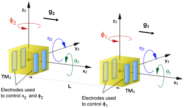
LISA Pathfinder (LPF) [1] was a differential accelerometer designed to demonstrate the free fall of geodesic reference test masses (TMs) at the level required for space-borne gravitational wave observatories such as LISA [2]. LPF achieved this by using a high precision interferometer to measure the relative acceleration, Δg, between two TMs placed in the same spacecraft (SC), along the x axis joining their centers (see Fig. 1). LISA is a truly open-loop differential acceleration measurement, with both TMs unforced inside separate drag-free spacecrafts. In LPF, closed-loop forces must be employed to keep the two TMs inside a single spacecraft, and this applied force is part of the measurement. Indeed, it is not possible for both TMs to be in free fall along x at the same time, like would be in LISA.
FIG. 1.
LPF capacitive actuation along x and housing coordinate systems. g1 and g2 indicate the stray acceleration experienced by TM1 and TM2, respectively.
In the normal LPF operations conditions, the observable Δg is measured by applying a calibrated compensation force gc on TM2 (all forces are expressed here per unit mass) and is extracted according to , with being the numerical second time derivative of the relative displacement Δx. The compensation is exerted by an electrostatic control loop continuously acting on TM2 with unity gain around 1 mHz. The reconstructed signal for Δg is dominated by gc for frequencies roughly below the 1 mHz band of the controller, while leads at higher frequencies where the TM is essentially free. The resulting time series for Δg depends on the actuator calibration [3]. In addition, the voltage noise of the actuator that applies gc introduces an extra force noise that was expected to be dominant at low frequencies [4].
To measure acceleration noise in a LISA-like configuration without x axis applied forces, a dedicated noise measurement using intermittent free fall has been designed [5]. This alternative technique aims at estimating the residual noise in Δg independent of the actuator calibration and free of actuation noise, and to characterize, by comparison, the contribution of actuation noise measured in standard operations. This configuration was tested in the LPF free-fall mode (or “drift” mode) experiment in which the compensation force on TM2 is applied intermittently in the form of high amplitude pulses with period of a few seconds, in between which the TM is let to fly with no compensation force along x.
The free-fall mode provides a measurement of the noise in Δg that coincides with that measured in the standard LPF configuration with continuous control and thus it confirms, as an independent measurement, the LPF performance. Indeed, actuation noise measured in flight conditions was a not a dominant contributor around 1 mHz, thus removing the x actuator produced a small effect on the acceleration noise spectrum. Moreover, the presented result demonstrates the functionality of an alternative control for space-based gradiometers [6], where force gradients are measured from the applied compensation force needed to hold the TM steady.
LISA Pathfinder instrument.—
Two gold-platinum cubic test-masses separated by ∼38 cm form the core instrument of LPF [7]. Both are in free fall inside a single SC with no mechanical contact and each of them is contained within an electrode housing [8], which serves as a 6 degree-of-freedom capacitive sensor and electrostatic force and torque actuator. TM2 is forced by an electrostatic suspension control loop to stay at a fixed distance from TM1, along x and thus centered in its own electrode housing. A second controller, called drag free, feeds the thrusters to keep the SC to follow TM1.
Given the quadratic dependence of force on voltage, the force fluctuation associated with an actuation voltage amplitude fluctuation depends on the force levels applied by each electrode. The same four electrodes actuate in x and ϕ (see Fig. 1), with an actuation scheme that keeps the stiffness constant [4] according to the maximum net forces and torques allowed, called “authorities.” The resulting x-force noise from actuation amplitude fluctuations depends both on the net applied x/ϕ force and on the x/ϕ authorities (the actuation scheme and noise model are presented in an upcoming publication).
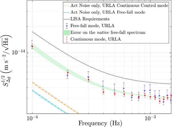
Based on a preflight analysis that considered Δgdc = 650 pm/s2—based on conservative gravitational balance precision estimates [9] and measured actuation amplitudes between 3 and 8 ppm/Hz1/2—actuation amplitude fluctuations were considered as the leading low frequency acceleration noise source for LPF at roughly 7 fm/s2/Hz1/2 at 1 mHz [4] (this analysis considered Δgdc ≈ 650 nm/s2 and ϕ dc angular accelerations of 2 nrad/s2, with 10% larger actuation authorities to accommodate transient dynamics). Over the mission, different levels of force and torque authority were implemented, beginning with the nominal configuration programmed before flight to accommodate potentially large gravitational imbalances, with x-force authority of 1100 pm/s2 (see Table I). The in-flight observed dc force imbalance was much smaller, always below 20 pm/s2 along x [3] with angular accelerations of −1.1 and 0.2 nrad/s2 for TM1 and TM2. This allowed reducing the authorities from nominal to the URLA configuration levels, with 26 pm/s2 x-force authority (see Table I). In this configuration, used for the measurements that established the published LPF differential acceleration noise floor [3, 10], the actuation noise, as estimated from a dedicated in-flight measurement campaign employing various force levels, is less than 20% of the total acceleration noise power measured over the 0.1 to 1 mHz band [11] (see the dashed line in Fig. 4).
TABLE I.
Free-fall mode measurement data set. The table includes the authority levels, duration (Δt, in hours), initial flight amplitude (Δx0), and TM2 stiffness . In both cases is in agreement (1σ) with the values resulting from the system dynamics calibration presented in Ref. [12]. The force authority values in bracket refer to the continuous control.
| Authority scheme | Start date | Δt | Δx0 | ||||
|---|---|---|---|---|---|---|---|
| [pm/s2] | [nrad/s2] | [nrad/s2] | (2016) | [h] | [nm] | [1=s2 × 10−7] | |
| Nominal | 0 (1100) | 15 | 15 | 09/06 | 18 | ∼40 | −7.12 ± 0.03 |
| URLA | 0 (26) | 2.2 | 1.4 | 18/12 | 132 | ∼30 | −4.53 ± 0.09 |
FIG. 4.
Acceleration noise estimate with free-fall mode in URLA ϕ authority compared with that in continuous actuation mode in URLA and the LISA requirements [2]. The free-fall ASD (dots) results from 20 periodograms, while the continuous noise run (asterisks) is ∼18 days long (78 periodograms), both calculated at 1σ confidence interval and according to the method presented in [10]. Shadowed area: estimate of the “native” free-fall spectrum. Dashed lines: actuation noise predictions.
Removing the x-axis actuation with the free-fall mode thus, in these flight conditions, is expected to have only a small impact on the measured acceleration noise (we note that during the free-fall mode the ϕ actuation torque is still applied continuously). Nevertheless, the free-fall mode experiment still represents an independent measurement of the differential acceleration without any actuator, immune to possible actuation nonlinearities or calibration inaccuracies.
Experiment description and calibration.—
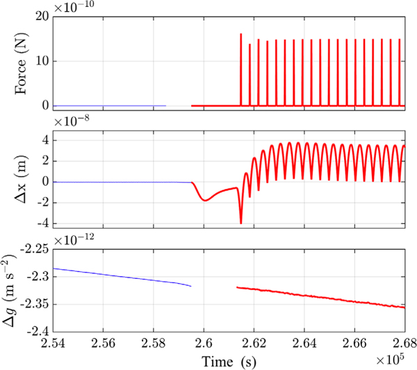
The free-fall mode implemented on LPF is a special actuation scheme where the electrostatic control on TM2 is switched on the sensitive x axis only for a very short duration (≤ 5 s). In particular, an impulse controller tracks the TM2 displacement, x2, during the flight and estimates the impulse necessary to push it back on the other side against the static field it experiences on board the SC. Then, the impulse-flight cycle is repeated (see Fig. 2) [5,13]. The flight interval, Tflight, is set by the maximum displacement allowed along x2 (≈10 μm), based on the preflight estimate of the gravitational imbalance. The experiments presented here are implemented with a fixed experimental time, Texp = Tflight + Timp, of 350.2 s, while impulse durations (Timp) of 1 s and 5 s were used in the two measurements. Figure 2 depicts the start of the first experiment with free-fall mode performed with Timp = 1 s and following a noise run executed in continuous control mode. As visible in the middle panel, the free fall mode is characterized by a wide dynamic range in displacement (tens of nm), in contrast with the continuous mode (tens of pm [13]).
FIG. 2.
Time series of TM2 force (top), relative displacement, Δx (middle), and Δg (bottom) measured in June 2016. The thin lines refer to a noise measurement with continuous control on TM2 in URLA authority, while the thick lines indicate a free-fall mode measurement in nominal authority. The discontinuity in the top panel stems from the use of different telemetry packets. The transient phase between the two runs is discarded in the bottom panel.
The main observable of LPF, Δg, is calculated with free-fall data as follows:
| (1) |
where is the electrostatic force gradient (“stiffness”), coupling TM2 to the SC and grot(t) is the contribution of the inertial forces acting on the TMs which are described and calculated in Ref. [12]. Differently from the definition of Δg in Ref. [10], the control force on TM2 is excluded in Eq. (1), being zero by definition in free-fall mode. In addition, the differential stiffness coupling the SC motion to Δg is neglected in our analysis, as it is too small to impact the result.
To retrieve the stiffness on TM2, , we fit flight by flight, as described in Ref. [13]. The resulting parameter values are averaged over the flights to get a single estimate. Then, the inertial contribution is subtracted from the residuals of the fit [see Eq. (1)] according to the procedure explained in Ref. [12].
Measurement data set.—
The free-fall mode experiment was performed seven times between June and December 2016, with stable and reliable control operation in various actuation configurations. This Letter presents the one-day measurement executed in June with ϕ authority based on preflight analyses (nominal authority) and the last run, with one week duration, performed in December with lower authority levels on ϕ (URLA authority). The intermediate measurements were used for planning the last long run, which was implemented to limit the flight amplitude within tens of nm. Indeed, the large dynamic range achieved in free-fall mode, compared to the continuous control mode, impacts the interferometer readout. In addition, it increases timing error issues, as observed also in the dedicated on-ground testing campaign performed with a torsion pendulum facility [14]. In this context, to reduce the gravitational imbalance between the TMs measured in December, TM1 was actuated along x with a constant out of loop force with amplitude of 11.2 pN, which was then subtracted from Δg. It has been verified that this force does not introduce significant noise or calibration errors.
Table I reports details and calibration results of the two free-fall mode measurements presented here.
Data analysis.—
The analysis of the free-fall mode experiment is challenging due to the presence of impulses. Estimating the noise in Δg without actuation implies limiting the analysis to the free-fall periods alone, effectively “gapping” data to be insensitive to the noise from the high-force impulses. The effect of gaps on the spectrum must be characterized, especially at low frequency, where the noise is expected to be lower than in presence of control [11].
In general, gaps can corrupt the spectral estimation, in the form of spectral leakage from both high and low frequencies, thus introducing a systematic bias in the underlying spectrum. Gaps can be masked with smooth spectral windows or filled with synthetic noise. In this Letter, we present the results obtained by applying the “Blackman-Harris gap zero” (BHGZ) technique (see Ref. [14] for a full review, except for the bias removal). The method, implemented using the dedicated data analysis toolbox, LTPDA [15], consists in filling the gaps with zero numerically by means of a rectangular-wave window, after having low-pass filtered and decimated the Δg time series. The name of the approach refers to the shape of the filter chosen, that is a minimum 4-term Blackman-Harris (BH) window. The filter is applied to reduce the aliasing caused by the rectangular-wave window and it is a finite impulse response (FIR) filter to avoid mixing in the gaps. Indeed, compared to smoother windows, the rectangular-wave window produces a relevant spectral leakage of the noise, from high frequency into the low frequency band of the spectrum. Finally, the downsampling is imposed by the numerical limitation of the procedure applied to remove, from the spectrum, the remaining bias due to gaps. This procedure will be described below, while implementation details of the BHGZ technique are found in Refs. [13,16].
The PSD of filtered, decimated, and gapped data is estimated with the same technique as for the continuous data described in Ref. [3], with errors estimation based on χ2 statistics [10]. Then, it is normalized for the transfer function of the BH filter and finally corrected for the bias induced by gaps.
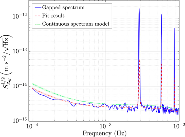
The spectral bias in free-fall data appears in the form of peaks at harmonics of the gap frequency (≡1/Texp∼2.8 mHz, see Fig. 3), observed after the multiplication of data by the rectangular-wave window. In addition, the amplitude of the gapped spectrum is reduced compared to that of continuous data, due to removal of data points, as reported e.g., in Ref. [20] and discussed also in the Supplemental Material [16], and this reduction scales with the gap size. In particular, in case of white noise, the normalization factor needed to compensate for the missing points set to zero, is equal to the inverse of the rectangular-wave duty cycle, as demonstrated in Ref. [14].
FIG. 3.
Fit results to free-fall data, measured in December 2016, to remove the bias from the spectrum (see the text for details). The peaks are excluded from the analysis and hence not fitted.
To remove the bias we follow “a pseudo-inverse” approach, described in detail in the Supplemental Material [16], based on looking for the theoretical shape of the spectrum that, through the action of the rectangular-wave window, reproduces the experimental spectrum. In practice, we fit the gapped spectrum to a smooth continuous model, we assume underneath data, which is convolved with the rectangular-wave window. In our case, the low-frequency noise only is modeled and the fit is performed at samples away from the peaks which we do not model. Indeed, we are mainly interested in removing the bias at low frequencies in order to estimate the noise in absence of the compensation force on TM2. The noise model, reported in Eq. (7) in the Supplemental Material [16], is based on the measured noise with continuous actuation [10] and it is precise enough as we achieve a good quality of fit [see, as an example, Fig. 2(b) in the Supplemental Material [16]].
The fit parameters are then used to trace the “native” spectrum of free-fall mode data without gaps, as explained in the Supplemental Material [16]. Figure 3 shows the result, in terms of Δg ASD (amplitude spectral density), of this procedure on data of the free-fall mode experiment carried out in December. The result obtained from the best fit to the ASD of data (solid line) is indicated by the dashed line, while the dash-dotted line is the model for the underlying continuous differential acceleration noise spectrum, resulting from our analysis, which converts into the dashed line when gaps are inserted. Thus, the bias is removed from the experimental gapped spectrum (solid line), by multiplying it by the ratio between the dash-dotted and the dashed lines. The effective experimental curve, with points appropriately scaled by the ratio of the dash-dotted and dashed lines, is shown by the dot data points in Fig. 4. Details of the analysis of December data can be found in the Supplemental Material [16].
Applying the technique on continuous control Δg data, with artificially inserted gaps, accurately recovers the spectrum obtained when analyzing the full continuous data set. The results of the method calibration are reported in the Supplemental Material [16].
Results.—
URLA authority: Figure 4 shows the Δg ASD of the free-fall mode experiment performed with URLA ϕ authority (asterisk data points), compared with that measured with continuous control mode in the same authority and just after the free-fall mode experiment (dot data points). Figure 4 includes the actuation noise predictions in URLA authority for both the measurements [11,13], showing that actuation noise does not dominate the low frequency spectrum in URLA continuous control mode and that it is expected to lessen, in free-fall mode, by roughly 20% at 0.1 mHz in ASD. The shadowed area behind the data points coincides with that of the dash-dotted line of Fig. 3. As visible, at frequencies below 1 mHz the Δg estimate in URLA free-fall mode agrees, within 1σ, with that measured in continuous control. Thus, removing the x control does not significantly reduce noise along the sensitive axis, since actuation noise in continuous mode is already dominated by the ϕ control, which does not change in free-fall mode.
While the noise reduction is not resolvable, the free-fall mode result represents an important confirmation of the LPF differential acceleration benchmark without applied forces. It also confirms that the low frequency noise excess, visible around 0.1 mHz and currently under investigation [10], is not caused by inaccuracies in the x-force subtraction, as the free-fall mode completely removes such contribution: we can state that noise from possible errors in the x-actuator calibration is below our detection threshold. To conclude, the free-fall mode experiment in the low ϕ uthority confirms, as an independent measurement, the LPF performance achieved in continuous control mode.
Nominal authority:
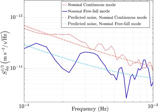
The results of the one-day experiment executed with free-fall mode in nominal ϕ authority, is depicted in Fig. 5 (thick solid line). The thin solid line indicates a Δg estimate measured in the period of the free-fall run with nominal continuous control. The picture includes the expected low-frequency noise at that period of time for both the measurements (dashed lines) [11]. As visible, in this case turning off the nominal authority (∼1100 pm/s2) x actuator, reduces noise at low frequency effectively, matching the predictions of suppression of actuation noise along the sensitive axis, which in turn dominates the spectrum when active. The free-fall mode thus can be considered an alternative technique to eliminate actuation noise when this is a limiting factor.
FIG. 5.
Comparison of Δg ASD between the free-fall mode experiment executed in June 2016 in nominal ϕ authority (thick solid line, 2 periodograms) and the continuous control mode run carried out in May 2016 in the same authority (thin solid line, 3 periodograms). The dashed lines are the noise predictions as explained in the text.
To conclude, though the noise due to the x control does not dominate the low-frequency band in the low authority scheme, as confirmed by the free-fall mode results, actuation noise enters in the LISA noise budget through the ϕ control. In this context, the free-fall mode experiment has provided an acceleration noise measurement in an actuation configuration similar to that of LISA.
Supplementary Material
Acknowledgments
This work has been made possible by the LISA Pathfinder mission, which is part of the space-science program of the European Space Agency. The French contribution has been supported by CNES (Accord Specific de projet CNES 1316634/CNRS 103747), the CNRS, the Observatoire de Paris and the University Paris-Diderot. E. Plagnol and H. Inchauspé would also like to acknowledge the financial support of the UnivEarthS Labex program at Sorbonne Paris Cité (ANR-10-LABX-0023 and ANR-11-IDEX-0005-02). The Albert-Einstein-Institut acknowledges the support of the German Space Agency, DLR. The work is supported by the Federal Ministry for Economic Affairs and Energy based on a resolution of the German Bundestag (FKZ 50OQ0501 and FKZ 50OQ1601). The Italian contribution has been supported by Agenzia Spaziale Italiana and Istituto Nazionale di Fisica Nucleare. The Spanish contribution has been supported by Contracts No. AYA2010-15709 (MICINN), No. ESP2013-47637-P, and No. ESP2015-67234-P and No. ESP2017-90084-P (MINECO), and 2017-SGR-1469 (AGAUR). M. Nofrarias acknowledges support from Fundacion General CSIC (Programa ComFuturo). F. Rivas acknowledges support from a Formación de Personal Investigador (MINECO) contract. The Swiss contribution acknowledges the support of the Swiss Space Office (SSO) via the PRODEX Programme of ESA. L. F. acknowledges the support of the Swiss National Science Foundation Project Number 200021-162449. The UK groups wish to acknowledge support from the United Kingdom Space Agency (UKSA), the University of Glasgow, the University of Birmingham, Imperial College, and the Scottish Universities Physics Alliance (SUPA). J. I. Thorpe and J. Slutsky acknowledge the support of the U.S. National Aeronautics and Space Administration (NASA).
References
- [1].McNamara P, Vitale S, Danzmann K. (LISA Pathfinder Science Working Team), LISA Pathfinder, Classical Quantum Gravity 25, 114034 (2008). [Google Scholar]
- [2].Amaro-Seoane P et al. , Laser interferometer space antenna, arXiv:1702.00786. [Google Scholar]
- [3].Armano M et al. , Sub-Femto-g Free Fall for Space-Based Gravitational Wave Observatories: LISA Pathfinder Results, Phys. Rev. Lett 116, 231101 (2016). [DOI] [PubMed] [Google Scholar]
- [4].Antonucci F et al. , From laboratory experiments to LISA Pathfinder: Achieving LISA geodesic motion, Classical Quantum Gravity 28, 094002 (2011). [Google Scholar]
- [5].Grynagier A, Fichter W, and Vitale S, The LISA Pathfinder drift mode: Implementation solutions for a robust algorithm, Classical Quantum Gravity 26, 094007 (2009). [Google Scholar]
- [6].Rummel R, Yi W, and Stummer C, GOCE gravitational gradiometry, J. Geod 85, 777 (2011). [Google Scholar]
- [7].Carbone L, Cavalleri A, Dolesi R, Hoyle CD, Hueller M, Vitale S, and Weber WJ, Characterization of disturbance sources for LISA: Torsion pendulum results, Classical Quantum Gravity 22, S509 (2005). [Google Scholar]
- [8].Dolesi R, Bortoluzzi D, Bosetti P, Carbone L, Cavalleri A, Cristofolini I, DaLio M, Fontana G, Fontanari V, Foulon B, Hoyle CD, Hueller M, Nappo F, Sarra P, Shaul DNA, Sumner T, Weber WJ, and Vitale S, Gravitational sensor for LISA and its technology demonstration mission, Classical Quantum Gravity 20, S99 (2003). [Google Scholar]
- [9].Armano M et al. , Constraints on LISA Pathfinder’s self-gravity: Design requirements, estimates and testing procedures, Classical Quantum Gravity 33, 235015 (2016). [Google Scholar]
- [10].Armano M et al. , Beyond the Required LISA Free-Fall Performance: New LISA Pathfinder Results down to 20 μHz, Phys. Rev. Lett 120, 061101 (2018). [DOI] [PubMed] [Google Scholar]
- [11].Weber WJ et al. (to be published).
- [12].Armano M et al. , Calibrating the system dynamics of LISA Pathfinder, Phys. Rev. D 97, 122002 (2018). [Google Scholar]
- [13].Giusteri R et al. , The free-fall mode experiment on LISA Pathfinder: First results, J. Phys. Conf. Ser 840, 012005 (2017). [Google Scholar]
- [14].Russano G, Cavalleri A, Cesarini A, Dolesi R, Ferroni V, Gibert F, Giusteri R, Hueller M, Liu L, Pivato P, Tu HB, Vetrugno D, Vitale S, and Weber WJ, Measuring fN force variations in the presence of constant nN forces: a torsion pendulum ground test of the LISA Pathfinder free-fall mode, Classical Quantum Gravity 35, 035017 (2018). [Google Scholar]
- [15].Hewitson M et al. , Classical and quantum gravity data analysis for the lisa technology package, Classical Quantum Gravity 26, 094003 (2009). [Google Scholar]
- [16]. [See Supplemental Material at http://link.aps.org/supplemental/10.1103/PhysRevLett.123.111101, sections “BHGZ method implementation” for implementation details of the BHGZ technique, “Final considerations” for discussion about the amplitude of the spectrum peaks, “Bias removal algorithm” for details on the bias removal algorithm, “Bias removal on free-fall mode data measured in December” for the bias removal procedure applied on data of free-fall mode, “Calibration of the method with continuous noise data” for the bias removal procedure applied on continuous data for calibration purposes, which includes Refs.]
- [17].Vitale S et al. , Data series subtraction with unknown and unmodeled background noise, Phys. Rev. D 90, 042003 (2014). [Google Scholar]
- [18].Ferraioli L, Congedo G, Hueller M, Vitale S, Hewitson M, Nofrarias M, and Armano M, Quantitative analysis of LISA pathfinder test-mass noise, Phys. Rev. D 84, 122003 (2011). [Google Scholar]
- [19].Welch P, The use of fast Fourier transform for the estimation of power spectra: A method based on time averaging over short, modified periodograms, IEEE Trans. Audio Electroacoust 15, 70 (1967). [Google Scholar]
- [20].Baghi Q, Métris G, Bergé J, Christophe B, Touboul P, and Rodrigues M, Regression analysis with missing data and unknown colored noise: Application to the MICROSCOPE space mission, Phys. Rev. D 91, 062003 (2015). [Google Scholar]
Associated Data
This section collects any data citations, data availability statements, or supplementary materials included in this article.


