Abstract
Photoacoustic (PA) imaging provides morphological and functional information about angiogenesis and thus is potentially suitable for breast cancer diagnosis. However, the development of PA breast imaging has been hindered by inadequate patients and a lack of ground truth images. Here, we report a digital breast phantom with realistic acoustic and optical properties, with which a digital PA-ultrasound imaging pipeline is developed to create a diverse pool of virtual patients with three types of masses: ductal carcinoma in situ, invasive breast cancer, and fibroadenoma. The experimental results demonstrate that our model is realistic, flexible, and can be potentially useful for accelerating the development of PA breast imaging technology.
1. Introduction
Worldwide, breast cancer is the leading type of cancer in women, contributing 25.4% of the total number of new cases diagnosed in 2018 [1]. It has been proved that the key to breast cancer survival is early diagnosis [2–4]. Mammography is currently the gold standard for breast cancer screening which, however, has lower sensitivity in women with dense breasts [5,6]. Ultrasound (US) is seen as an adjunct to mammography, but suffers from speckle artifacts and low specificity [7,8]. Magnetic resonance imaging (MRI) poses a large financial burden and sometimes requires the use of intravenous contrast agents that can potentially cause damage to the human body [9–11]. It is also hampered by often excluding patients due to claustrophobia, pacemakers, etc. In recent years, photoacoustic computed tomography (PACT) is growing rapidly as a non-invasive imaging modality for breast cancer screening and diagnosis, which has overcome many of these limitations [12–17].
In PACT, the biological tissue being imaged is illuminated by a pulsed laser. Scattered photons are selectively absorbed by chromophores in the tissue, giving rise to fast thermal expansion, which generates ultrasonic waves [18]. The photoacoustically generated sound waves are then received by ultrasonic transducers and digitally processed to reconstruct images of light absorption contrast. Since scattered photons are employed for contrast generation while ultrasound waves are used for signal localization, the imaging depth of PACT can reach several centimeters, way beyond the optical diffusion limit of 1 mm in typical biological tissues [19,20]. By scanning the wavelength of the illumination light, the absorption spectrum of each image voxel can be measured, which contains important functional information, such as saturation of oxygen (sO2) [13,16]. To date, several clinical PACT systems for breast imaging have been built with vastly different configurations and image characteristics [12–17].
For the following reasons, in silico studies are important for continued development and improvement of PACT imaging devices: (1) In PACT, the properties of the signals are coupled with image features such as blood vessels’ orientation and spatial density. A computer-generated phantom with various anatomically and physiologically relevant properties can help engineers optimize system designs. Moreover, building an imaging system and doing clinical experiments are costly and time consuming. It can be very inefficient to iteratively optimize the system via real experiments. In contrast, system design based on numerical phantoms is fast and cost-effective. (2) The digital phantom provides a gold standard for both anatomical and functional imaging, thus making system evaluation more quantitative. (3) A fair comparison among different imaging systems requires that the same object be imaged and evaluated, thus all systems need to be present on site to image the same patient. However, different systems can be compared more easily by in silico experiments using data generated by the same numerical phantom. (4) As computing and storage capacities increase, the difficulties of performing accurate simulations reduce.
For the above reasons, researchers have conducted several numerical studies [21–28] to simulate the PA imaging process of human breasts, yet these models have limitations that remain unaddressed. Current PA breast phantoms are based either on segmentation of MRI/mammography dataset [21–25] or on the combination of a few simple objects [26–28]. Details of these studies are provided in Table 1. Compared with the existing PA breast phantoms, we aim to cover their advantages and bring several improved features: (1) Realistic phantoms for human breast with high resolution and accurate physical properties of different tissue types. (2) Automatic and fast generation of breast models to accommodate a variety of breast types. (3) Improved and extendable precision in modelling different types of breast masses. (4) A comprehensive and easy-to-use package tailored to simulate realistic PACT systems, which enables users to freely modify parameters. To meet these goals, we applied a newly reported software, known as the VICTRE breast phantom [29]. This software generates random voxelized digital breast phantoms step by step that contain skin, nipple, lactiferous duct, terminal duct lobular unit (TDLU), interlobular gland tissue, fat, suspensory ligament, muscle, artery, and vein. The general characteristics of the breast (volume, gland fraction, etc.) are selected by the user or randomly sampled from a population-based distribution [30].
Table 1. Overview of PA digital breast phantoms.
| Study year | Breast modeling technique | Tissue type | Lesion model | Advantages and limitations |
|---|---|---|---|---|
| 2014 [26] | Combination of a few simple objects | Skin and fat | None | A model easy to accomplish but oversimplified |
| 2017 [21] | Threshold segmentation from contrast-enhanced MRI data | Skin, vessel, fat and fibroglandular tissue | None | Accurate representation of the breast anatomy but suffers from large computational burden and huge time consumption, only 50 patients’ data were acquired |
| 2017 [27] | Combination of a few simple objects | Background soft tissue | A circular target that had absorption properties of hemoglobin | A 2D model easy to accomplish but oversimplified, the optical parameters are inaccurate |
| 2018 [22] | Load the initial PA pressure from X-ray breast image after processing | Background soft tissue visualized by X-ray images | Benign and malignant tumors segmented from X-ray images | Large database available, easy to accomplish, while the real PA images are significantly different from the simulated ones, the X-ray images can’t give enough contrast between malignant and benign tumors as well as between vessels and other background tissues |
| 2018 [28] | Combination of a few simple objects | Glandular tissue and vessels | None | A 2D model easy to accomplish but oversimplified |
| 2019 [23] | Application of the second phantom | Skin, vessel, fat and fibroglandular tissue | Tumors acquired from mice studies (imaged with fluorescent imaging system) | Tumor models derived from mice studies; no distinction between tumor types |
| 2020 [24] | Segmentation of the digital mammography (DM) dataset based on deep learning | Skin, fat and fibroglandular tissue | Segmented from DM dataset | Large database available, high efficiency but only in 2D, does not include vessel structures which are crucial for PA imaging |
| 2021 [25] | Reconstruct the 3D breast model through a series of 2D US B-scan slices, then perform segmentation | Skin, fat and fibroglandular tissue | Segmented manually from US images | Accurate representation of the breast anatomy but does not include vessel structures, suffers from large time consumption, no distinction between tumor types |
A model for breast masses has been introduced as a supplement of the digital breasts [31], this mass model, however, was oversimplified for PACT. Following the same modeling strategy, we make further improvements to the mass model based upon anatomical and physiological properties of the breast. Breast cancers are classified as non-invasive breast cancer and invasive breast cancer (IBC). Non-Invasive breast cancers are those which do not spread, derived mostly from the mammary ductal epithelium [32]. Thus our breast mass models are classified into three major types: (1) benign fibroadenoma, (2) ductal carcinoma in situ (DCIS), and (3) IBC. Utilizing the new phantom, we simulated PA wave propagation and detection in two dimensions (2D) and three dimensions (3D). Then we compared PA images of different types of healthy breasts. In addition, we performed studies using our breast tumor models, and presented overlaid PA and ultrasound (US) images containing both anatomical and functional information. PA/US dual-modality imaging provides complementary information from different contrast mechanisms, which enhances each individual contrast for improved clinical performance.
2. Methods
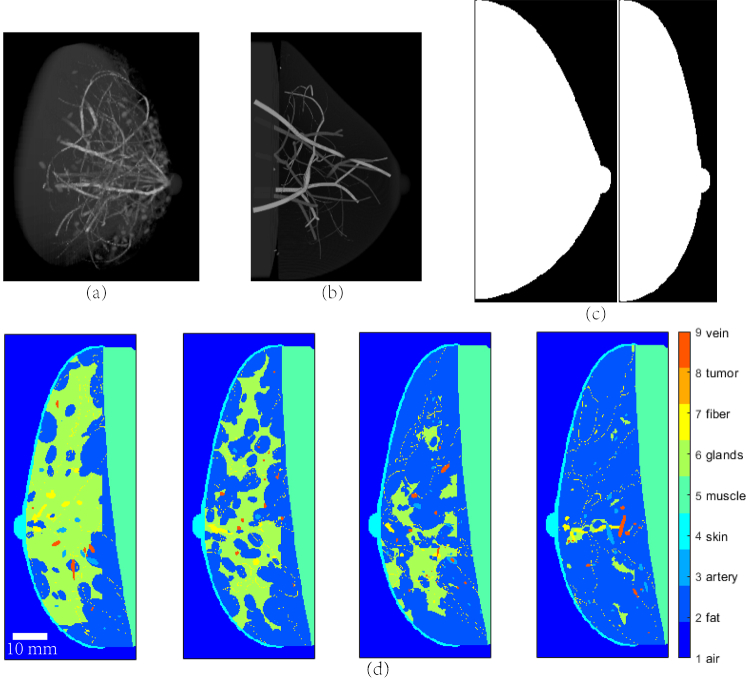
Figure 1(a) presents an overview of the VICTRE breast model. To account for different patient positions (i.e., standing, supine, or prone), we adjusted the simulation parameters to change the profile of the breast, as shown in Fig. 1(c) where the left profile corresponds to the standing position while the right one mimics the supine position. The model also allows for the control of breast density, which is known to affect lesion detection in digital mammography (DM) [5,6]. The breasts of the female population fall into four density categories: extremely dense (0.548 glandular volume fraction (GVF)), heterogeneously dense (0.339 GVF), scattered fibroglandular densities (0.143 GVF), and almost entirely fat (0.071 GVF). According to this, we created four types of breast models corresponding to different breast densities (shown in Fig. 1(d)) [33]. Once the model parameters are fixed, breast tissue textures are randomly generated with pre-determined statistical values. In this way, multiple breast models of each type can be made (with different microscopic tissue realizations) by simply changing a random number seed [30].
Fig. 1.
Digital breast models. (a) 3D view of the breast model; (b) Distribution of blood vessels in the breast; (c) Side view of the breast profile in standing and supine positions; (d) Four types of breasts with different densities (from left to right: extremely dense, heterogeneously dense, scattered fibroglandular densities, and almost entirely fat).
To set up a breast model, a series of deformations are performed to create a breast with a particular volume and shape, starting from a base quadratic surface. Then the Voronoi technique [34] is applied to generate the initial glandular compartments and grow a ductal tree-like structure with terminal duct lobular units from the nipple into each compartment. The next step involves using the Perlin noise function [35] to create a realistic gland/fat tissue interface and the Cooper's ligament network. Then, to simulate a realistic vascular network, random trees (one for each major vein and artery in human breast) originating from the backing muscle layer of the phantom are generated. A cost function is used to yield a preferential growth direction of the main branch in the skin surface/chest wall direction. These main branches spawn smaller secondary branches and the process proceeds recursively to fill the breast volume. In general, the generated vascular network tends to have bigger vessels near the skin surface and the chest wall, while smaller vessels are in between (Fig. 1(b)). After finalizing the breast model, the stochastic Gaussian random sphere model [36] is used to generate a tumor mass in the center, and the iterative fractal branch algorithm is performed to add complex needle-like structures simulating microvascular clusters around the breast mass [31]. Studies have identified distinct patterns in PA images, corresponding to various vasculatures associated with different types of tumors [37–39]. For example, a study [39] reported that the centripetal blood vessel structure was observed in the PA images of breasts diagnosed with IBC, whereas intratumoral spotty signals were observed in the DCIS cases. In another study [37], the PA images showed absence of hemoglobin within or around fibroadenoma. Moreover, using diffuse optical spectroscopy and tomography, researchers have found that malignancies are characterized by a substantially higher concentration of blood, with significantly lower oxygenation than normal or benign tissue [40–42]. We modified the mass model taking into account the above observations, and produced three types of mass models: fibroadenoma, DCIS, and IBC (Fig. 2). In our phantom, fibroadenomas are modeled by a regular oval-shaped mass without vessels inside or microvasculature around. Meanwhile, IBC's are irregularly shaped and have a centripetal blood vessel structure as well as surrounding microvasculatures. For DCIS, we add a few thin vessels inside an irregular mass, to simulate the observed intratumoral spotty patterns. We also decrease the oxygenation level within malignant masses. The digital mass is embedded into the breast phantom in the end. TDLUs are the primary site for cancer formation. As a result, we choose the locations for the insertion of masses where a TDLU has been generated, including the chest wall.
Fig. 2.
Breast cancer models. (a) Fibroadenoma; (b) DCIS; (c) IBC.
In our study, MCmatlab was used as the simulation platform. The outer boundary for the simulation zone is a rectangular cuboid whose internal volume is uniformly divided into cubic voxels. The user assigns to each voxel a medium or tissue type, described by its absorption coefficient µa, its scattering coefficient µs, and its Henyey–Greenstein scattering anisotropy factor g at the applied optical wavelength. Then an input light beam is simulated by launching photon packets and calculating their energy deposition in the simulated volume using a Monte-Carlo model (MC model) [43].
Near-infrared (NIR) light is preferred for PACT due to the relatively low optical scattering and absorption [44]. Hence we conducted our simulation at 700 nm and 900 nm using the optical parameters listed in Table 2 [45,46]. The optical properties of lactiferous duct, TDLU, and suspensory ligament are approximately equal, we define them all as the fiber tissue [47]. As it is computationally challenging to assign individual blood vessel elements with different optical properties [44], we assume average blood oxygenation (sO2) of 75% for vein and 95% for artery.
Table 2. Optical properties of breast tissues for 3D Monte Carlo simulation.
| Tissue | µa (mm-1) | µa (mm-1) | µs (mm-1) | µs (mm-1) | g | Refractive |
|---|---|---|---|---|---|---|
| type | 700 nm | 900 nm | 700 nm | 900 nm | index, n | |
| Fat | 0.062 | 0.067 | 7.30 | 6.80 | 0.98 | 1.3 |
| Artery | 0.330 | 0.795 | 7.14 | 5.56 | 0.90 | 1.3 |
| Skin | 0.048 | 0.033 | 16.70 | 21.27 | 0.90 | 1.3 |
| Muscle | 0.052 | 0.054 | 7.36 | 6.67 | 0.93 | 1.3 |
| Glands | 0.036 | 0.057 | 11.20 | 7.90 | 0.96 | 1.3 |
| Fiber | 0.013 | 0.016 | 11.50 | 16.18 | 0.90 | 1.3 |
| Cancer | 0.033 | 0.035 | 8.70 | 15.10 | 0.90 | 1.3 |
| Vein | 0.500 | 0.655 | 7.14 | 5.56 | 0.90 | 1.3 |
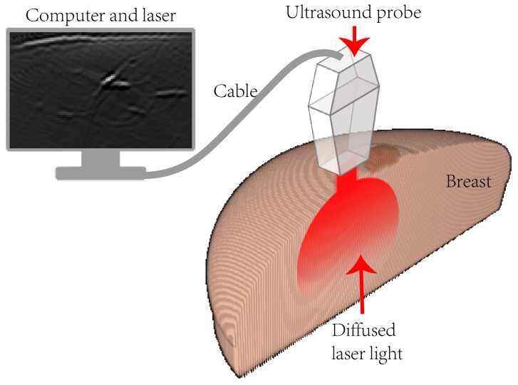
In this study, we simulated PA imaging using linear transducer arrays. Linear arrays have been extensively used in PACT for breast imaging due to their commercial availability and compatibility with traditional ultrasound scanners [44]. Figure 3 illustrates the schematic of the imaging setup in our simulations. A 128-element linear array (2.5 MHz central frequency, -6 dB bandwidth of 70%) is placed on top of the breast of a patient in the supine position. A linear illumination pattern is chosen because it can provide relatively homogenous optical fluence at the imaging plane [44]. Light sources are placed outside the model and provide a uniform fluence at the breast surface with an area of 12 × 12π mm2. The light incident position and the center line of the transducer imaging plane are in coincidence. The background medium is non-scattering and non-absorbing, and has no refractive index mismatch with the breast model.
Fig. 3.
The schematic of the imaging setup.
We employed the k-Wave toolbox [48] for all the simulations regarding PA wave propagation and detection. The initial PA pressure was simulated based on the optical fluence distribution from the 3D MC model. The initial pressure gave rise to PA waves that propagated in tissues which were acoustically heterogeneous (Table 3) [49–51] with negligible acoustic attenuation. The PA signals were detected by transducer elements that were curved in one dimension to create elevational focusing. This allowed us to simulate the acoustic sectioning of a real handheld probe. The detected signals were then band-pass filtered to account for the finite bandwidth imposed by the ultrasound detector and its electronics. To form an image, we used the simplest delay-and-sum (DAS) reconstruction algorithm.
Table 3. Acoustic properties of breast tissues for k-Wave simulation.
| Tissue type | Speed of sound (m/s) | Density (kg/m3) |
|---|---|---|
| Fat | 1440 | 910 |
| Artery | 1578 | 1050 |
| Skin | 1624 | 1109 |
| Muscle | 1588 | 1090 |
| Glands | 1500 | 1000 |
| Fiber | 1750 | 1170 |
| Cancer | 1400 | 950 |
| Vein | 1578 | 1050 |
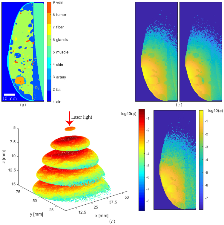
Since the optical absorption spectra of oxygenated hemoglobin (HbO2) and deoxygenated hemoglobin (Hb) are different, sO2 can be determined from PA images acquired at multiple wavelengths. In the simplest case when the spectral coloring effect is negligible, and Hb and HbO2 are the dominant absorbers, total concentration of hemoglobin (tHb) and sO2 can be estimated by acquiring images at two wavelengths, followed by linear spectral unmixing [52]. To maximize the estimation accuracy, the two selected wavelengths should be on the opposite side of the isosbestic point [37]. Wavelength-dependent light scattering has a substantial influence on the optical fluence maps. For the breast phantom shown in Fig. 4(a), the light fluence distribution at 700 nm and 900 nm are shown in Fig. 4(b), the distribution of the optical fluence has become quite different after propagating just a few millimeters (Fig. 4(c)).
Fig. 4.
MC simulation of the light fluence distribution in a numerical phantom. (a) Cross-sectional view of the digital breast; (b) Optical fluence distributions at 700 nm (left) and 900 nm (right); (c) Optical fluence difference, 3D view (left) and slice view (right).
The artifacts in the PA images are mainly caused by the limited detection angular coverage, the heterogeneous acoustic properties, and insufficient spatial sampling frequency. The existence of the artifacts increases the difficulty of sO2 estimation, and thus we employ the region growth method for image segmentation and accordingly apply a mask to selectively calculate sO2 in the area of interest.
To display the reconstructed PA images on top of gray-scale ultrasound images (as many researchers do in their experiments), we also simulate pseudo-B-mode ultrasound images using the same numerical phantom. These images are termed ‘pseudo’ because they are not created by rigorous simulations; rather, they are directly rendered from the echogenicity feature maps of the numerical phantoms. The image is formed by first adding motion blur to the input acoustic impedance map and then multiplying it with a speckled noise pattern. Such speckle patterns are generated from our in vivo US images by the exemplar-based texture synthesis method [53].
3. Results
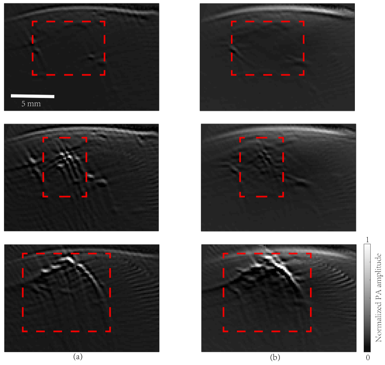
All our MC simulations of light fluence distribution were performed in 3D, while for acoustic propagation and detection we did both 2D and 3D simulations. 2D simulations are much faster, while 3D simulations are in principle more accurate. PA images corresponding to the three types of breast mass models (shown in Fig. 2) are given in Fig. 5, from which we conclude that the 2D- and 3D-models are quite similar in terms of revealing anatomical structures, and both suffer from artifacts due to the limited-view detection [54,55]. For the 2D model, the reconstructed PA image can better recover the actual anatomical structures, because out-of-plane artifacts are absent. In the following simulations, we choose to use the 2D model for higher efficiency.
Fig. 5.
Simulated PA images. Row 1: fibroadenoma, Row 2: DCIS, Row 3: IBC. (a) PA wave propagation and detection were performed in 2D; (b) PA wave propagation and detection in 3D. Red dashed boxes indicate the lesions.
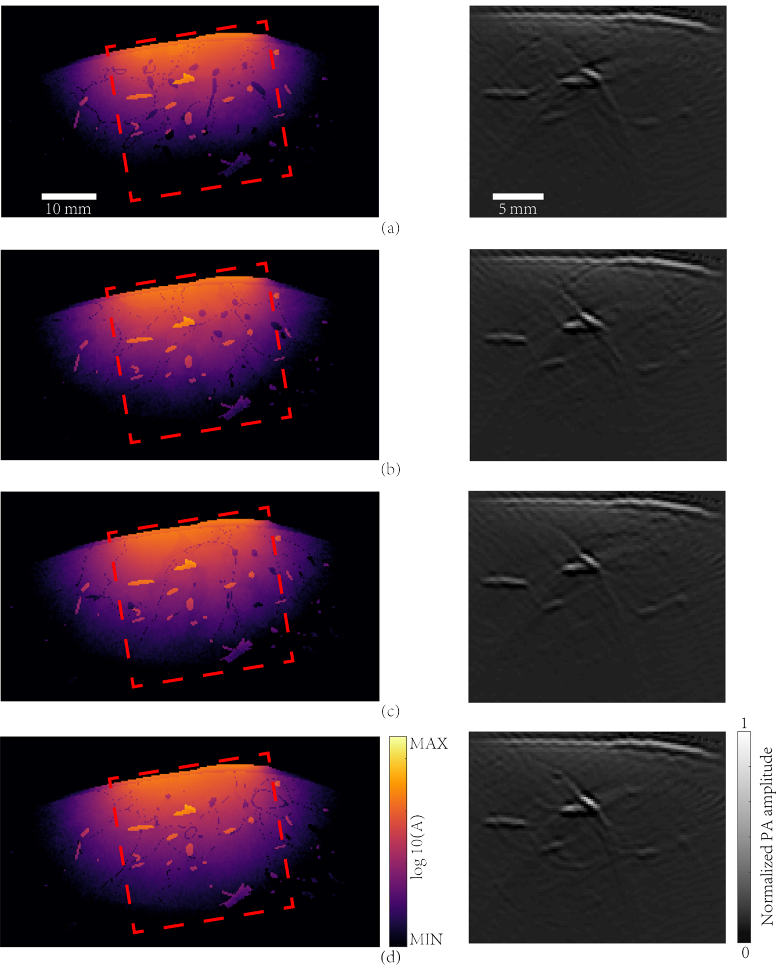
An extra simulation was carried out to investigate if various breast density affects the PA image features, especially imaging depth. Four breast models corresponding to different breast densities as displayed in Fig. 1(d) were used in the simulation. Considering the optical fluence distributions could be remarkably affected by the vascular distribution, we applied the same vascular structure. MC simulation was performed at a wavelength of 900 nm and light intensity on the breast surface was about 150 mw cm-2. After that we employed a 128-element linear ultrasonic transducer array (0.75 mm pitch, 0.25 mm inter-element spacing) for signal detection. The received PA signals were reconstructed by DAS algorithm assuming a uniform speed of sound of 1500 m/s. Figure 6 shows that breast density does not have a significant influence on the optical fluence distribution. The penetration depths were all around 2 cm for the four types of breasts with dramatically different density, according to the MC simulation. As expected, in the right column of Fig. 6, PA features reconstructed at the same depth were similar for all four cases. This observation agrees with experiments, that is, compared to mammography, PA image quality is less sensitive to radiographic density of the breast [12].
Fig. 6.
Simulation results for different types of breasts. Column on the left are images of light energy deposition at a wavelength of 900 nm. Column on the right are images of PA initial pressure reconstructed with a uniform speed of sound of 1500 m/s. (a) Extremely dense breast; (b) Heterogeneously dense breast; (c) Breast with scattered fibroglandular; (d) Breast with almost entirely fat. Red dashed boxes represent the region shown in the PA images.
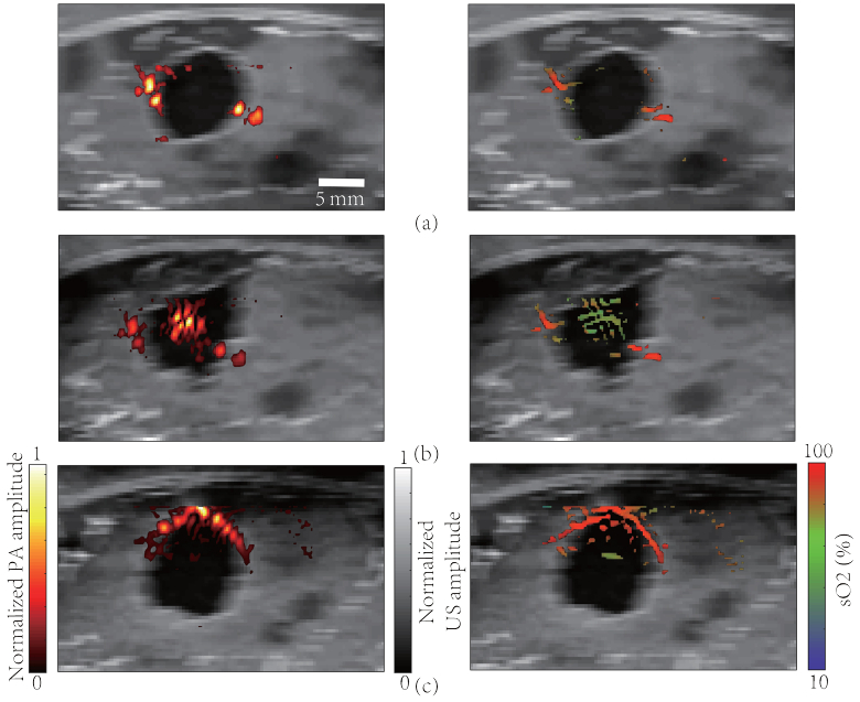
Using our simulation platform, in silico imaging can be easily performed and compared with experimental ones. As an example, we simulated PA/US dual-modality imaging of a dense breast with an embedded lesion whose center was located 1 cm below the skin. To measure sO2, we acquired PA images at both 700 nm and 900 nm and then employed linear spectral unmixing for demodulation. However, linear unmixing only works when the excitation spectrum stays unchanged at different depths [56]. As we have demonstrated in Fig. 4(c), the excitation spectrum is affected by wavelength-dependent light scattering and absorption. This could induce substantial error in the sO2 measurement. Thus for deep-seated targets optical fluence compensation is essential for accurate sO2 imaging [56,57]. Here we simply assumed that perfect compensation has been made to create the gold standard sO2 maps. By applying the mask segmented from the reconstructed PA images before calculating, we can eliminate most artifacts without loss of the features. Figure 7 illustrates three images corresponding to three types of tumors with their respective PA features, the anatomical structure of the digital phantom has been shown in Fig. 5(a). The embedded mass had a diameter of 8 mm, representative of an early-stage lesion, which can be clearly seen from the US images as hypoechoic masses. These images exhibit the common features of PA/US dual-mode imaging where US provides the grayscale structural background while superimposed PA images indicate functional information, such as tHb and sO2 [37]. The figures show the possible advantage of PA/US imaging over US imaging alone. For example, in Fig. 7(c), the US image feature may suggest a benign lesion such as a fibroadenoma. However, the centripetal vessel with relatively low oxygenation, as well as increased blood supply around the mass, indicate possible malignancy. Figure 7(b) provides another example of how PA imaging may be useful for differentiating among subtypes of malignant mass.
Fig. 7.
Simulation results of PA/US dual-modality breast imaging. Left column: tHb images superimposed on grayscale ultrasound images. The color scheme for PA signal is shown on the bottom left. Right column: sO2 images superimposed on grayscale ultrasound images. The color scheme for sO2 display is shown on the bottom right. (a) Fibroadenoma; (b) DCIS; (c) IBC.
4. Discussion
Malignant tumors are often associated with angiogenesis and reduced sO2 due to their aggressive growth [37]. Therefore, PA imaging is a potential candidate for breast cancer diagnosis and screening [12] thanks to its high sensitivity to morphological and functional changes of the vascular network. The development and clinical translation of the PACT technology can be accelerated by well-designed digital phantoms which have realistic physiological, anatomical and physical properties. Here, we introduce a breast phantom created from the computational methods. The phantom is not only realistic, but also flexible enough to allow adjustments of its density, shape, and detailed structural realization. We performed 3D MC simulation and used k-Wave to simulate acoustic propagation and detection. In our demonstrations, we chose to apply acoustic simulation in 2D for better efficiency without losing much accuracy. Based on the digital phantom, we also generated grayscale US images upon which pseudo-color PA images were superimposed.
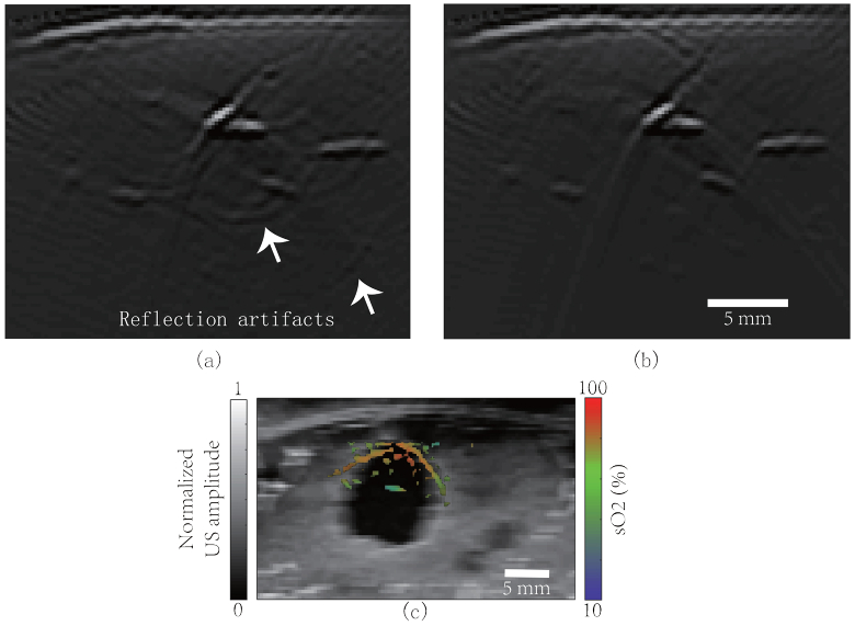
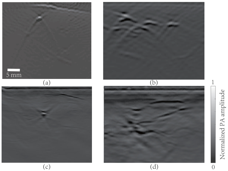
An advantage of this computational model is that it is designed specifically for photoacoustic imaging. The simulated tissue types, anatomical structures, and optical/acoustic properties are all chosen to be realistic. Based on the breast phantom, the simulated PA/US images have shown features that are commonly found in experimental images. This model also offers the capability of creating a large population of virtual patients having benign or malignant tumors, and with dramatically diverse tissue contents (density) and breast shapes. Used in conjunction with the optical and acoustic simulation software reported above, this phantom allows researchers to investigate a number of technical problems conveniently (since no real experiments are required) and quantitatively (since the gold standard is available). For example, different light illumination and detection schemes can be quantitatively compared and optimized, if the simulated results could emulate the real images. Similarly, the reflection artifacts and spectral coloring effect in PA imaging can also be analyzed. By comparing PA images generated from breasts that are acoustically heterogeneous (according to Table 3) and homogenous (speed of sound 1500 m/s, density 1000 kg/m3), the generation of reflection artifacts was clearly observed in Fig. 8(a-b). Likewise, we calculated the sO2 map around the mass (IBC) by linear unmixing, but without fluence compensation. In contrast with Fig. 7(c), the inaccurate estimation of sO2 (Fig. 8(c)) clearly reveals the spectral coloring effect [37,56]. Comparing our simulation results with the in vivo ones (obtained using a custom-made hand-held PA imaging probe, central frequency 2.5 MHz, bandwidth 55%, 128 channels), the synthetic images show highly similar features (Fig. 9). The digital phantom can be further improved iteratively using clinical data as feedback.
Fig. 8.
Using the model to study reflection artifacts and spectral coloring effect. (a) PA image of the breast (acoustically heterogeneous medium); (b) PA image of the breast (acoustically homogeneous medium);(c) PA + US imaging of an IBC mass. Color: sO2 map from multispectral PAI; grayscale: US image. sO2 estimation is different from Fig. 7(c) because no fluence compensation was performed.
Fig. 9.
Simulated PA images and clinical PA images. (a) Simulated blood vessel in normal breast; (b) Simulated tumor-related angiogenic vessels; (c) In vivo PA image of a healthy breast; (d) In vivo PA image of breast tumor angiogenesis.
In practice, due to limitations in bandwidth, spatial sampling density, and viewing angle, important vascular features may be distorted or even absent in the reconstructed image; due to acoustic reflections and reverberations, artifacts can be generated and superimposed on true structures; due to the spectral coloring effect, using two colors for sO2 demodulation can be highly unreliable. Optimization of the imaging hardware can be systematically pursued in silico using the digital phantoms, taking into account all the above-mentioned complexities.
Now, open source dataset for PA breast imaging is insufficient, while a large amount of data can be generated digitally to train neural networks for various tasks such as image reconstruction, vessel segmentation, lesion detection, artifacts removal, quantitative imaging, etc.. Another advantage of using digital phantoms for algorithm development is that gold standards are readily available.
The mass models used in this study were constructed based on a few cases of photoacoustic imaging results. These models are still quite limited to accurately represent the structural and functional diversity of real tumors and tumor microenvironments. The optical and acoustic properties and the exact 3D shapes of the solid tumors, as well as the morphology and physiological state of the vascular networks inside and surrounding the tumor due to angiogenesis, all need to be more accurately modelled in the future.
5. Conclusion
In this paper, we present a realistic, 3D digital breast phantom which exhibits the fine structures observed in in-vivo PA/US images. We find that although 3D acoustic model is more precise, 2D model is more efficient with sufficient accuracy. The numerical phantom is useful for researchers to develop PA systems for breast cancer imaging, and to investigate problems such as reflection artifacts and the spectral coloring effect. On the one hand, using a phantom with the real complexity of the human breast, it is possible to study the spectral coloring effect in detail. On the other hand, 3D modelling of photon transportation in digital breasts could provide information for more sophisticated optical fluence compensation. Using our phantom in conjunction with prior structural information (e.g., acquired using US imaging), and by properly adjusting tissue optical properties, we could customize a personalized compensation scheme for each patient. This is another potential application where our phantom can contribute to better functional PA imaging. Owing to insufficient number of cases reported of PA imaging of the breast, the mass model for different types of breast cancer is still rudimentary [38]. Our future research will focus on improving the mass model to better reflect the diversity and complexity of real tumors.
Funding
National Natural Science Foundation of China10.13039/501100001809 (61735016, 61971265); Fuzhou Institute for Data Technology (Innovation Fund).
Disclosures
The authors declare no conflicts of interest.
References
- 1.Bray F., Ferlay J., Soerjomataram I., Siegel R. L., Torre L. A., Jemal A., “Global cancer statistics 2018: GLOBOCAN estimates of incidence and mortality worldwide for 36 cancers in 185 countries,” CA: a Cancer J. Clin. 68(6), 394–424 (2018). 10.3322/caac.21492 [DOI] [PubMed] [Google Scholar]
- 2.Dizon D. S., Krilov L., Cohen E., Gangadhar T., Ganz P. A., Hensing T. A., Hunger S., Krishnamurthi S. S., Lassman A. B., Markham M. J., “Clinical cancer advances 2016: annual report on progress against cancer from the American Society of Clinical Oncology,” J. Clin. Oncology 34(9), 987–1011 (2016). 10.1200/JCO.2015.65.8427 [DOI] [PMC free article] [PubMed] [Google Scholar]
- 3.Miller A. B., Wall C., Baines C. J., Sun P., To T., Narod S. A., “Twenty five year follow-up for breast cancer incidence and mortality of the Canadian National Breast Screening Study: randomised screening trial,” Br. Med. J. 348(feb11 9), g366 (2014). 10.1136/bmj.g366 [DOI] [PMC free article] [PubMed] [Google Scholar]
- 4.Burton R., Bell R., “The global challenge of reducing breast cancer mortality,” The Oncologist 18(11), 1200–1202 (2013). 10.1634/theoncologist.2013-0315 [DOI] [PMC free article] [PubMed] [Google Scholar]
- 5.Pinsky R. W., Helvie M. A., “Mammographic breast density: effect on imaging and breast cancer risk,” J. Natl. Compr. Cancer Network 8(10), 1157–1165 (2010). 10.6004/jnccn.2010.0085 [DOI] [PubMed] [Google Scholar]
- 6.Freer P. E., “Mammographic breast density: impact on breast cancer risk and implications for screening,” Radiographics 35(2), 302–315 (2015). 10.1148/rg.352140106 [DOI] [PubMed] [Google Scholar]
- 7.Devolli-Disha E., Manxhuka-Kërliu S., Ymeri H., Kutllovci A., “Comparative accuracy of mammography and ultrasound in women with breast symptoms according to age and breast density,” Bosnian J. Basic Med. Sci. 9(2), 131–136 (2009). 10.17305/bjbms.2009.2832 [DOI] [PMC free article] [PubMed] [Google Scholar]
- 8.Hooley R. J., Scoutt L. M., Philpotts L. E., “Breast ultrasonography: state of the art,” Radiology 268(3), 642–659 (2013). 10.1148/radiol.13121606 [DOI] [PubMed] [Google Scholar]
- 9.Murphy K. J., Brunberg J. A., Cohan R. H., “Adverse reactions to gadolinium contrast media: a review of 36 cases,” AJR, Am. J. Roentgenol. 167(4), 847–849 (1996). 10.2214/ajr.167.4.8819369 [DOI] [PubMed] [Google Scholar]
- 10.Perazella M. A., “Gadolinium-contrast toxicity in patients with kidney disease: nephrotoxicity and nephrogenic systemic fibrosis,” Curr. Drug Safety 3(1), 67–75 (2008). 10.2174/157488608783333989 [DOI] [PubMed] [Google Scholar]
- 11.Ibrahim D., Froberg B., Wolf A., Rusyniak D. E., “Heavy metal poisoning: clinical presentations and pathophysiology,” Clin. Lab. Med. 26(1), 67–97 (2006). 10.1016/j.cll.2006.02.003 [DOI] [PubMed] [Google Scholar]
- 12.Lin L., Hu P., Shi J., Appleton C. M., Maslov K., Li L., Zhang R., Wang L. V., “Single-breath-hold photoacoustic computed tomography of the breast,” Nat. Commun. 9(1), 1–9 (2018). 10.1038/s41467-017-02088-w [DOI] [PMC free article] [PubMed] [Google Scholar]
- 13.Diot G., Metz S., Noske A., Liapis E., Schroeder B., Ovsepian S. V., Meier R., Rummeny E., Ntziachristos V., “Multispectral optoacoustic tomography (MSOT) of human breast cancer,” Clin. Cancer Res. 23(22), 6912–6922 (2017). 10.1158/1078-0432.CCR-16-3200 [DOI] [PubMed] [Google Scholar]
- 14.Haisch C., Eilert-Zell K., Vogel M. M., Menzenbach P., Niessner R., “Combined optoacoustic/ultrasound system for tomographic absorption measurements: possibilities and limitations,” Anal. Bioanal. Chem. 397(4), 1503–1510 (2010). 10.1007/s00216-010-3685-9 [DOI] [PubMed] [Google Scholar]
- 15.Montilla L. G., Olafsson R., Bauer D. R., Witte R. S., “Real-time photoacoustic and ultrasound imaging: a simple solution for clinical ultrasound systems with linear arrays,” Phys. Med. Biol. 58(1), N1–N12 (2013). 10.1088/0031-9155/58/1/N1 [DOI] [PubMed] [Google Scholar]
- 16.Becker A., Masthoff M., Claussen J., Ford S. J., Roll W., Burg M., Barth P. J., Heindel W., Schaefers M., Eisenblaetter M., “Multispectral optoacoustic tomography of the human breast: characterisation of healthy tissue and malignant lesions using a hybrid ultrasound-optoacoustic approach,” Eur. Radiol. 28(2), 602–609 (2018). 10.1007/s00330-017-5002-x [DOI] [PubMed] [Google Scholar]
- 17.Manohar S., Dantuma M., “Current and future trends in photoacoustic breast imaging,” Photoacoustics 16, 100134 (2019). 10.1016/j.pacs.2019.04.004 [DOI] [PMC free article] [PubMed] [Google Scholar]
- 18.Zhou Y., Yao J., Wang L. V., “Tutorial on photoacoustic tomography,” J. Biomed. Opt. 21(6), 061007 (2016). 10.1117/1.JBO.21.6.061007 [DOI] [PMC free article] [PubMed] [Google Scholar]
- 19.Xia J., Yao J., Wang L. V., “Photoacoustic Tomography: Principles and Advances,” Prog. Electromagn. Res. 147, 1–22 (2014). [DOI] [PMC free article] [PubMed] [Google Scholar]
- 20.Razansky D., Distel M., Vinegoni C., Ma R., Perrimon N., Köster R. W., Ntziachristos V., “Multispectral opto-acoustic tomography of deep-seated fluorescent proteins in vivo,” Nat. Photonics 3(7), 412–417 (2009). 10.1038/nphoton.2009.98 [DOI] [Google Scholar]
- 21.Lou Y., Zhou W., Matthews T. P., Appleton C. M., Anastasio M. A., “Generation of anatomically realistic numerical phantoms for photoacoustic and ultrasonic breast imaging,” J. Biomed. Opt. 22(4), 041015 (2017). 10.1117/1.JBO.22.4.041015 [DOI] [PMC free article] [PubMed] [Google Scholar]
- 22.Lan H., Duan T., Zhong H., Zhou M., Gao F., “Photoacoustic classification of tumor model morphology based on support vector machine: a simulation and phantom study,” IEEE J. Sel. Top. Quantum Electron. 25(1), 1–9 (2019). 10.1109/JSTQE.2018.2856583 [DOI] [Google Scholar]
- 23.Dantuma M., Lucka F., Jaros J., Teeby B., Cox B., Manohar S., “Breast tumor appearances in photoacoustic tomography from fine 3D optical-acoustic simulations (Conference Presentation),” in Photons Plus Ultrasound: Imaging and Sensing 2019 (International Society for Optics and Photonics, 2019), 10878, p. 108781I. [Google Scholar]
- 24.Ma Y., Yang C., Zhang J., Wang Y., Gao F., Gao F., “Human breast numerical model generation based on deep learning for photoacoustic imaging,” in 2020 42nd Annual International Conference of the IEEE Engineering in Medicine & Biology Society (EMBC) (IEEE, 2020), pp. 1919–1922. [DOI] [PubMed] [Google Scholar]
- 25.Han T., Yang M., Yang F., Zhao L., Jiang Y., Li C., “A three-dimensional modeling method for quantitative photoacoustic breast imaging with handheld probe,” Photoacoustics 21, 100222 (2021). 10.1016/j.pacs.2020.100222 [DOI] [PMC free article] [PubMed] [Google Scholar]
- 26.Wang G., Zhao H., Ren Q., Li C., “Simulation of light delivery for photoacoustic breast imaging using the handheld probe,” Chin. Opt. Lett. 12(5), 051703 (2014). 10.3788/COL201412.051703 [DOI] [Google Scholar]
- 27.Sowmiya C., Thittai A. K., “Simulation of photoacoustic tomography (PAT) system in COMSOL(R) and comparison of two popular reconstruction techniques,” in Medical Imaging 2017: Biomedical Applications in Molecular, Structural, and Functional Imaging (International Society for Optics and Photonics, 2017), 10137, p. 101371O. [Google Scholar]
- 28.Fadden C., Kothapalli S.-R., “A single simulation platform for hybrid photoacoustic and rf-acoustic computed tomography,” Appl. Sci. 8(9), 1568 (2018). 10.3390/app8091568 [DOI] [PMC free article] [PubMed] [Google Scholar]
- 29.Sharma D., Graff C. G., Badal A., Zeng R., Sawant P., Sengupta A., Dahal E., Badano A., “In silico imaging tools from the VICTRE clinical trial,” Med. Phys. 46(9), 3924–3928 (2019). 10.1002/mp.13674 [DOI] [PubMed] [Google Scholar]
- 30.Graff C. G., “A new, open-source, multi-modality digital breast phantom,” in Medical Imaging 2016: Physics of Medical Imaging (International Society for Optics and Photonics, 2016), 9783, p. 978309. [Google Scholar]
- 31.de Sisternes L., Brankov J. G., Zysk A. M., Schmidt R. A., Nishikawa R. M., Wernick M. N., “A computational model to generate simulated three-dimensional breast masses,” Med. Phys. 42(2), 1098–1118 (2015). 10.1118/1.4905232 [DOI] [PMC free article] [PubMed] [Google Scholar]
- 32.Nyayapathi N., Xia J., “Photoacoustic imaging of breast cancer: a mini review of system design and image features,” J. Biomed. Opt. 24(12), 1 (2019). 10.1117/1.JBO.24.12.121911 [DOI] [PMC free article] [PubMed] [Google Scholar]
- 33.Badano A., Graff C. G., Badal A., Sharma D., Zeng R., Samuelson F. W., Glick S. J., Myers K. J., “Evaluation of digital breast tomosynthesis as replacement of full-field digital mammography using an in silico imaging trial,” JAMA Netw. Open 1(7), e185474 (2018). 10.1001/jamanetworkopen.2018.5474 [DOI] [PMC free article] [PubMed] [Google Scholar]
- 34.Tuceryan M., Jain A. K., “Texture segmentation using Voronoi polygons,” IEEE Trans. Pattern Anal. Machine Intell. 12(2), 211–216 (1990). 10.1109/34.44407 [DOI] [Google Scholar]
- 35.Perlin K., “Improving noise,” in Proceedings of the 29th Annual Conference on Computer Graphics and Interactive Techniques (2002), pp. 681–682. [Google Scholar]
- 36.Muinonen K., “Introducing the Gaussian shape hypothesis for asteroids and comets,” Astron. Astrophys. 332, 1087–1098 (1998). [Google Scholar]
- 37.Oraevsky A. A., Clingman B., Zalev J., Stavros A. T., Yang W. T., Parikh J. R., “Clinical optoacoustic imaging combined with ultrasound for coregistered functional and anatomical mapping of breast tumors,” Photoacoustics 12, 30–45 (2018). 10.1016/j.pacs.2018.08.003 [DOI] [PMC free article] [PubMed] [Google Scholar]
- 38.Rao A. P., Bokde N., Sinha S., “Photoacoustic imaging for management of breast cancer: A literature review and future perspectives,” Appl. Sci. 10(3), 767 (2020). 10.3390/app10030767 [DOI] [Google Scholar]
- 39.Toi M., Asao Y., Matsumoto Y., Sekiguchi H., Yoshikawa A., Takada M., Kataoka M., Endo T., Kawaguchi-Sakita N., Kawashima M., “Visualization of tumor-related blood vessels in human breast by photoacoustic imaging system with a hemispherical detector array,” Sci. Rep. 7(1), 41970 (2017). 10.1038/srep41970 [DOI] [PMC free article] [PubMed] [Google Scholar]
- 40.Zhu Q., Huang M., Chen N., Zarfos K., Jagjivan B., Kane M., Hedge P., Kurtzman S. H., “Ultrasound-guided optical tomographic imaging of malignant and benign breast lesions: initial clinical results of 19 cases,” Neoplasia 5(5), 379–388 (2003). 10.1016/S1476-5586(03)80040-4 [DOI] [PMC free article] [PubMed] [Google Scholar]
- 41.Hsiang D., Shah N., Yu N., Su M.-Y., Cerussi A., Butler J., Baick C., Mehta R., Nalcioglu O., Tromberg B., “Coregistration of dynamic contrast enhanced MRI and broadband diffuse optical spectroscopy for characterizing breast cancer,” Technol. Cancer Res. Treat. 4(5), 549–558 (2005). 10.1177/153303460500400508 [DOI] [PubMed] [Google Scholar]
- 42.Chance B., Nioka S., Zhang J., Conant E. F., Hwang E., Briest S., Orel S. G., Schnall M. D., Czerniecki B. J., “Breast cancer detection based on incremental biochemical and physiological properties of breast cancers: A six-year, two-site study1,” Academic Radiol. 12(8), 925–933 (2005). 10.1016/j.acra.2005.04.016 [DOI] [PubMed] [Google Scholar]
- 43.Marti D., Aasbjerg R. N., Andersen P. E., Hansen A. K., “MCmatlab: an open-source, user-friendly, MATLAB-integrated three-dimensional Monte Carlo light transport solver with heat diffusion and tissue damage,” J. Biomed. Opt. 23(12), 1 (2018). 10.1117/1.JBO.23.12.121622 [DOI] [PubMed] [Google Scholar]
- 44.Tang Y., Yao J., “3D Monte Carlo simulation of light distribution in mouse brain in quantitative photoacoustic computed tomography,” arXiv preprint arXiv:2007.07970 (2020). [DOI] [PMC free article] [PubMed]
- 45.Peters V. G., Wyman D. R., Patterson M. S., Frank G. L., “Optical properties of normal and diseased human breast tissues in the visible and near infrared,” Phys. Med. Biol. 35(9), 1317–1334 (1990). 10.1088/0031-9155/35/9/010 [DOI] [PubMed] [Google Scholar]
- 46.Bashkatov A. N., Genina E. A., Tuchin V. V., “Optical properties of skin, subcutaneous, and muscle tissues: a review,” J. Innovative Opt. Health Sci. 04(01), 9–38 (2011). 10.1142/S1793545811001319 [DOI] [Google Scholar]
- 47.Jacques S. L., “Optical properties of biological tissues: a review,” Phys. Med. Biol. 58(11), R37–R61 (2013). 10.1088/0031-9155/58/11/R37 [DOI] [PubMed] [Google Scholar]
- 48.Treeby B. E., Cox B. T., “k-Wave: MATLAB toolbox for the simulation and reconstruction of photoacoustic wave fields,” J. Biomed. Opt. 15(2), 021314 (2010). 10.1117/1.3360308 [DOI] [PubMed] [Google Scholar]
- 49.Chivers R. C., Parry R. J., “Ultrasonic velocity and attenuation in mammalian tissues,” J. Acoust. Soc. Am. 63(3), 940–953 (1978). 10.1121/1.381774 [DOI] [PubMed] [Google Scholar]
- 50.Duck F. A., Physical Properties of Tissues: A Comprehensive Reference Book (Academic Press, 2013). [Google Scholar]
- 51.El-Brawany M. A., Nassiri D. K., Terhaar G., Shaw A., Rivens I., Lozhken K., “Measurement of thermal and ultrasonic properties of some biological tissues,” J. Med. Eng. Technol. 33(3), 249–256 (2009). 10.1080/03091900802451265 [DOI] [PubMed] [Google Scholar]
- 52.Villringer A., Chance B., “Non-invasive optical spectroscopy and imaging of human brain function,” Trends Neurosci. 20(10), 435–442 (1997). 10.1016/S0166-2236(97)01132-6 [DOI] [PubMed] [Google Scholar]
- 53.Wei L.-Y., Lefebvre S., Kwatra V., Turk G., “State of the art in example-based texture synthesis,” in (2009).
- 54.Vu T., Li M., Humayun H., Zhou Y., Yao J., “A generative adversarial network for artifact removal in photoacoustic computed tomography with a linear-array transducer,” Exp. Biol. Med. 245(7), 597–605 (2020). 10.1177/1535370220914285 [DOI] [PMC free article] [PubMed] [Google Scholar]
- 55.Deán-Ben X. L., Razansky D., “On the link between the speckle free nature of optoacoustics and visibility of structures in limited-view tomography,” Photoacoustics 4(4), 133–140 (2016). 10.1016/j.pacs.2016.10.001 [DOI] [PMC free article] [PubMed] [Google Scholar]
- 56.Li M., Tang Y., Yao J., “Photoacoustic tomography of blood oxygenation: a mini review,” Photoacoustics 10, 65–73 (2018). 10.1016/j.pacs.2018.05.001 [DOI] [PMC free article] [PubMed] [Google Scholar]
- 57.Cox B. T., Laufer J. G., Beard P. C., Arridge S. R., “Quantitative spectroscopic photoacoustic imaging: a review,” J. Biomed. Opt. 17(6), 061202 (2012). 10.1117/1.JBO.17.6.061202 [DOI] [PubMed] [Google Scholar]


