

Abstract
Single-walled carbon nanotubes (SWNT) are attractive targets for the formation of high-density sensor arrays. Their small size and high reactivity could allow for the spatial and temporal study of extracellular products to a degree which greatly surpasses contemporary sensors. However, current methods of SWNT immobilization produce a low fluorescence yield that requires a combination of high magnification, exposure time, and laser intensity to combat, thus limiting the sensor’s applications. In this work, a platform for the immobilization of SWNT sensors with increased fluorescence yield, longevity, fluorescence distribution, and fast reaction times is developed.
Keywords: nanotechnology, carbon nanotubes, nitric oxide, platform design, extracellular signaling factor detection
Graphical Abstract:
INTRODUCTION
The detection and study of extracellular products has been under intensive study for the past several decades because of the fundamental role signaling molecules play in coordinated biological processes.1–4 There are currently multiple methods for the temporal study of extracellular products but very few allow both temporal and spatial detection.5–10 Recently, a new group of sensors based on DNA wrapped fluorescence single-walled carbon nanotubes (SWNTs) have shown the potential to provide high-quality spatial and temporal information regarding a wide range of cellular signaling molecules, proteins, and analytes including nitric oxide (NO), hydrogen peroxide (H2O2), glucose, dopamine, norepinephrine, serotonin, lipids, oligonucleotides, and the RAP-1/HIV-1 integrase proteins.11–20 In addition to their ability to sense key signaling molecules, SWNT offer several advantages over other sensors, including a fluorescence signal in the near-infrared (nIR) tissue transparency window, no blinking or photobleaching, and, as a result of its small size, the potential to create high density sensor arrays.21–29 Depositing SWNT on cell culture substrates is a critical step in the formation of sensor arrays; however, current methods for the deposition of DNA–SWNT complexes are limited almost entirely to nonspecific or electrostatic interactions which are not well characterized.11,14–17,30,31 The most common method of SWNT deposition relies on the use of an aminopropyl silane that is bound to a glass substrate.11,14,15,31 The partially negative DNA strand that wraps the SWNT sensor (i.e., the DNA backbone) is allowed to interact with the partially positive aminopropyl derivatized surface, generating a SWNT-functionalized surface through electrostatic interactions. Unfortunately, (3-aminopropyl)triethoxysilane (APTES)-based deposition has traditionally produced a low concentration of SWNT on the surface, and a correspondingly low fluorescence yield, requiring data to be collected through high laser power and/or high exposure times or to be collected for individual sensors independently, not an entire field of view.11,14,15,31 Collecting data for individual, unevenly dispersed SWNT can limit the ability of researchers to examine large-scale signaling events, high laser intensity can have a negative impact on the sample because of excessive heating, and high exposure times limit the ability to collect temporal information. A new method of sensor immobilization, which can increase the amount of SWNT present at the surface and thus increase the total fluorescence output, is required.
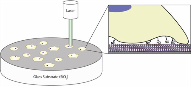
This paper outlines a new method for the immobilization of SWNT sensors based upon the avidin-biotin interaction (Figure 1). An epoxy silane linker is used to covalently bind avidin to a glass substrate, and a biotin is added to oligo tails on the DNA that wraps the SWNT. The interaction between the surface and the SWNT results in an anchoring system that utilizes a combination of electrostatic and bio-affinity interactions. The results demonstrate successful addition of biotin to SWNT sensors without altering function, the covalent linkage of avidin to a glass substrate, and an increase in total fluorescence output without altering SWNT distribution, response time, or longevity. A NO-sensing SWNT sensor was used as a proof of concept for this platform because of its relative simplicity compared to some of the more complex DNA–SWNT sensors15,20 and its widespread application possibilities, including analysis of vasodilation, immune function, neurological signaling, and cancer development, which are all dependent upon NO spatial concentrations.32–41 Other NO-sensing mechanisms, including the Griess assay and electrochemical probes, do not allow for the spatial and temporal sensing capabilities of the SWNT sensors, which means that this new platform will be able to provide information about extracellular NO concentrations that were previously undetectable.
Figure 1.
Schematic of the fabrication of SWNT-derivatized substrates. The method contains four main steps for the newly developed avidin platforms (a,b) and three steps for the APTES platforms (c,d), which serve as the current standard method of SWNT sensor attachment to a glass surface. The first step, outlined in red, is the addition of the piranha solution to the glass slides to generate hydroxyl groups at the surface. Next, epoxy silane, outlined in light green, or aminopropyl silane, outlined in dark green, is added and reacts with the exposed hydroxyl groups and bind to the surface. For avidin platforms, there is one more step than for the APTES platforms, outlined in blue is the addition of the avidin group. The final step for both platforms is the addition of the SWNT. The biotinylated SWNT will interact with the avidin on the platform to create a strong noncovalent bond. The nonbiotinylated SWNT interacts with the avidin platform through electrostatic interactions. Both the biotinylated and non-biotinylated SWNT interact with the APTES surface through electrostatic interactions.
RESULTS AND DISCUSSION
Characterization of Biotinylated SWNT.
Figure 1 shows a schematic of the fabrication process used to create SWNT-immobilized surfaces via chemical and/or electrostatic interactions. The chemical interactions require biotinylation of the SWNT, which was accomplished by using a 1:1 volumetric ratio of 5′-biotinylated (AT)15 and (AT)15 to wrap SWNT (referred to as biotinylated SWNT throughout the paper). To determine the importance of the biotin on the development of the platform, a control sample of 100% (AT)15-wrapped SWNT is used (referred to as non-biotinylated SWNT throughout the paper).The first step in the process was to determine the ability of the biotinylated (AT)15 to wrap the SWNT without altering the sensor’s performance. Measurements were conducted to ensure that the sensors maintained their characteristic peak and intensity. A visual inspection of Figure 2a shows that the addition of the biotin did not greatly alter the sensor’s spectrum but the quantification of the system was also performed to ensure the statistical significance of the comparison.
Figure 2.
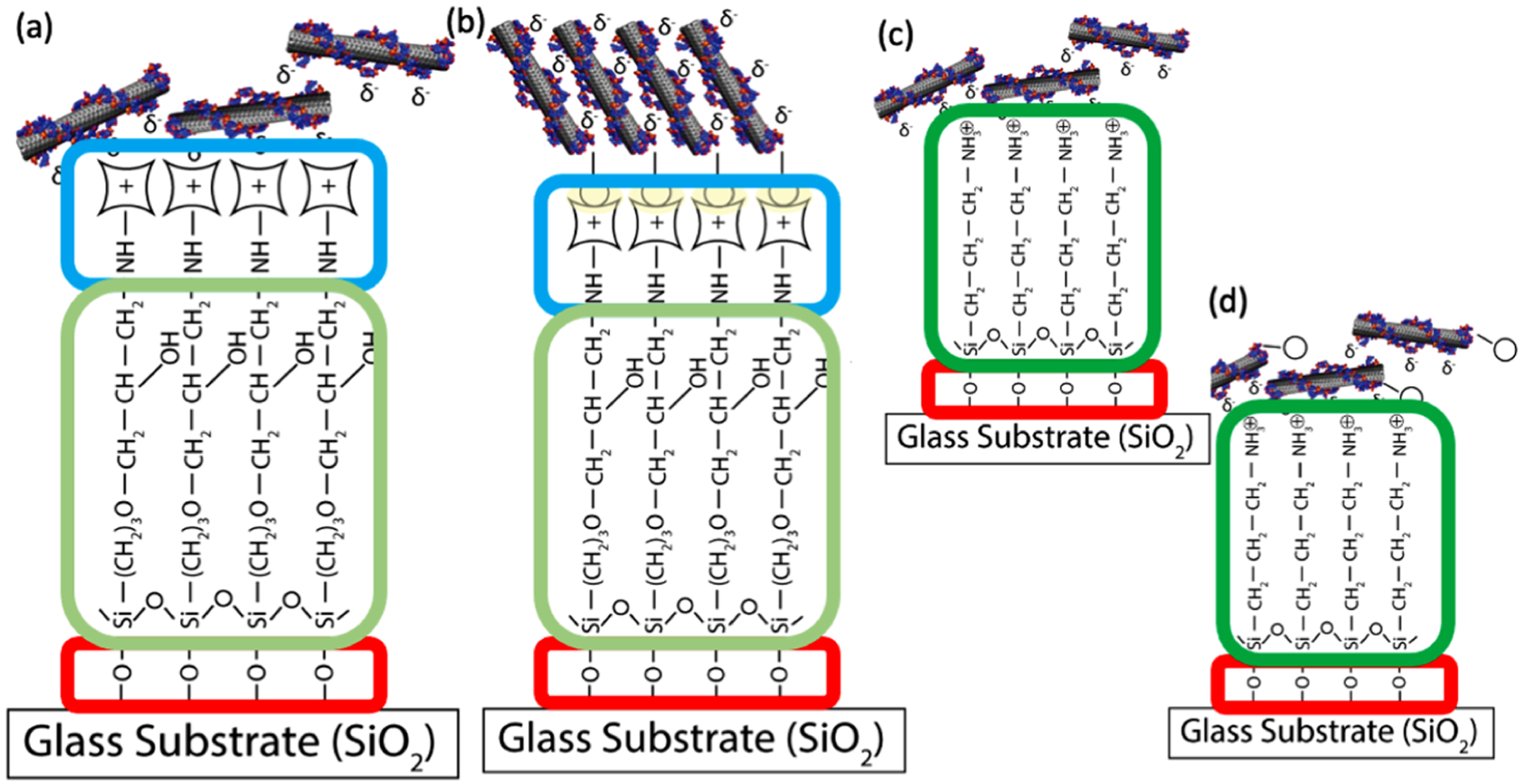
Behavioral properties of biotinylated SWNT compared to those of the non-biotinylated SWNT. (a) Fluorescence emission spectra for 30 mg/L biotinylated SWNT and non-biotinylated SWNT. (b,c) Isolated 990 intensity values for biotinylated SWNT and non-biotinylated SWNT are not significantly different (as designated by n.s.). (d) Normalized fluorescence spectra demonstrate nearly identical fwhm values. (e) Fluorescence quenching curves in response to identical concentrations of NO demonstrate that biotinylation has a negligible effect on SWNT quenching response. (n = 3 for a–e, unpaired t-test demonstrated a lack of statistical differences between samples).
The SWNT sensor used in this paper is a fluorescence quenching sensor, displaying a decrease in peak intensity (990 nm) in the presence of NO (the mechanism of action for the fluorescence quenching was previously published in an article by Zhang et al.).11 Therefore, the 990 nm value for these SWNT, when not in the presence of NO, needs to remain high so that a decrease in intensity can be easily visualized. To check the impact of the biotin on the sensors, we isolated the 990 nm peak from each spectrum and aggregated them. Biotinylated and non-biotinylated samples produced average 990 nm intensity values of 529.6 and 583.2 a.u., respectively (Figure 2b,c). An unpaired t-test determined that the differences in peak values is insignificant (p = 0.1759), and therefore, the biotinylation does not impact peak fluorescence intensity.
Next, the full width half maximum (fwhm) values of the spectra were investigated because fwhm describes the shape of the spectrum and can be used as a measurement of spectrum similarity. The fluorescence spectra were normalized with respect to their value at 990 nm, aggregated, and plotted (Figure 2d, table of values in Supporting Information Table S3). An unpaired t-test was conducted and demonstrated an insignificant difference between the fwhm of both spectra (p = 0.0680), indicating that biotinylation had no significant impact on the fwhm of the SWNT emission peak.
Finally, the responsiveness of the SWNT was tested for its sensing capabilities. The quenching capacity of biotinylated and non-biotinylated SWNT was determined through the collection of fluorescence intensity data during the addition of NO (Figure 2e). The visual inspection of quenching rates demonstrated remarkably similar profiles. The quantification of the data shows that the time to reach 99% quenching was 18.8 and 16.8 s for biotinylated and non-biotinylated SWNT, respectively. Statistical analysis with an unpaired t-test show that there is no significant difference between the quenching rates and capacity of the biotinylated and non-biotinylated SWNT.
The results presented in Figure 2 demonstrate that the biotinylated and non-biotinylated SWNT are extremely similar (not statistically different). Therefore, the addition of the biotin, which is utilized in the next experiments, does not alter the sensor.
Building the Platform.
Once the capabilities of the biotinylated SWNT were determined, the platform needed to be built. Each step of the platform development process was tested to ensure that the reactions occurred as expected. For ease of understanding, the data for each type of test are displayed together for every step of the platform building process.
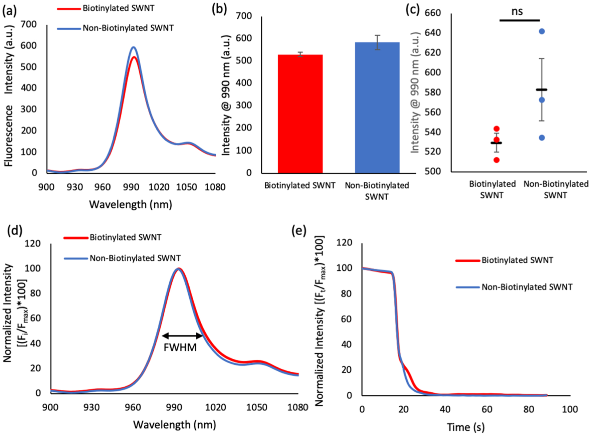
Contact angle measurements were taken stepwise during surface development (Figure 3a–c). Piranha treated, 3-glycidoxypropyltrimethoxysilane (3-GPTMS) functionalized, and avidin functionalized slides provided contact angle measurements of <5, 58.5, and 29.6°, respectively. Piranha treatment, which is responsible for the formation of hydroxyl groups, showed an extremely low contact angle, the 3-GPTMS functionalization led to an increase in contact angle, and the addition of the avidin lowered the contact angle because of its hydrophilicity, all three results are consistent with literature values, indicating that the expected functionalization occurred at each step of the fabrication process.43,47–49
Figure 3.
Substrates were characterized with contact angle and XPS at each step of the process. Contact angle measurements are shown for (a) piranha treated slides, which demonstrated a contact angle of <5° that is consistent with glass substrates treated in this manner. (b) GPTMS treated slides show a characteristic increase in a contact angle of 58.5°. (c) Avidin treated slides show a decrease in the contact angle to 29.6°, which can be attributed to avidin’s hydrophilicity. (n ≥ 3, SE ≤ 1.3 for all three conditions) XPS spectra data are shown for each of these steps. (d) C 1s clearly demonstrates an increase in the total carbon after 3-GPTMS and avidin functionalization indicating their presence on the surface. (e) N 1s peak showed no substantial peaks until avidin functionalization indicating avidin’s presence on the surface. (f,g) Both the O 1s and Si 2p peaks demonstrate shielding effects as the addition of silane and later avidin decrease the signal intensity of the underlying SiO2 framework.
In order to further confirm functionalization, X-ray photoelectron spectroscopy (XPS) was employed to observe key atomic spectra, specifically the C 1s, N 1s, O 1s and Si 2p chemical peaks (Figure 3d–g). Piranha treated slides showed a small C 1s peak, indicative of background carbon levels, no nitrogen peak, and strong Si 2p and O 1s peaks, which result from the underlying SiO2 substrate. Following 3-GPTMS functionalization, an increase in carbon content is observed, which may be attributed to the carbon in the arm of the silane, no nitrogen peak is observed, and the Si 2p/O 1s peaks show a decrease from piranha treatment results, which can be attributed to shielding effects from the silane (XPS is a highly depth dependent technique). Finally, when avidin is derivatized on the surface, the carbon peak increases greatly because, like most proteins, avidin is carbon dense; a nitrogen peak appears, which can be contributed to the amino acids and primary amines found in avidin; and the Si 2p/O 1s peaks show even greater shielding effects. Atomic percentage values were calculated using Avantage software and are in accordance with atomic spectra (Table S1).
APTES surfaces were generated similar to the way that 3-GPTMS surfaces were built. Contact angle measurements obtained from APTES demonstrated its successful deposition on the glass surface (Figure S3a,b). The C1s spectra from APTES indicates an increase in carbon following APTES deposition, which is attributable to the carbon found in the silane arm. The N 1s peak shows no nitrogen until after the APTES functionalization step, which is associated with the aminopropyl head of APTES. The O 1s and Si 2p peaks both show the shielding effects of APTES derivatization (Figure S3c). Atomic percentages were also calculated and are in good accordance with XPS spectra (Table S2).
Quantification of SWNT on the Platform.
The importance of the avidin in the binding of the biotinylated SWNT was tested to ensure that any observed reactions were occurring because of the avidin–biotin interaction and not as a result of nonspecific binding. These experiments were performed by measuring the concentration of biotinylated and non-biotinylated SWNT that were attached to the surface after each step of the platform building process, specifically the untreated, piranha treated, and 3-GPTMS-, avidin-, or APTES-functionalized platforms (Figure 4a,b).
Figure 4.
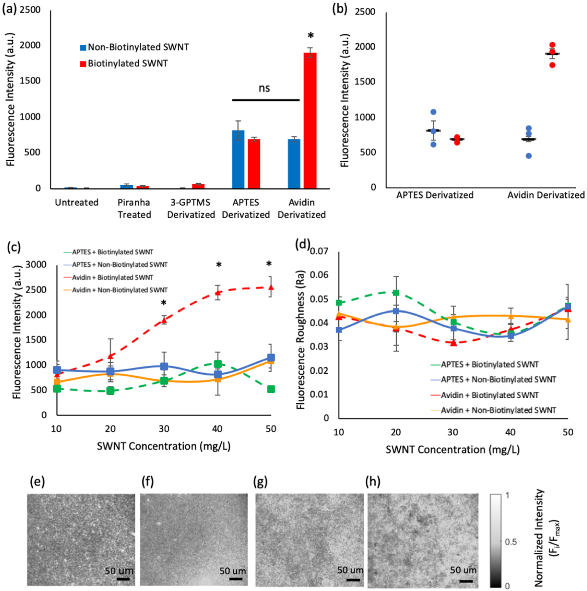
Ability of each platform to create an evenly distributed, high concentration of SWNT was tested. (a) Either non-biotinylated or biotinylated SWNT (30 mg/L) was applied to intermediates in the derivatization processes and completely derivatized surfaces. Intermediate surfaces showed little to no retention of SWNT while APTES and avidin showed a significant increase in SWNT retention. The SWNT/substrate combinations of APTES + non-biotinylated SWNT, APTES + biotinylated SWNT, and avidin + non-biotinylated SWNT showed no significant differences (labeled as ns), while the avidin + biotinylated SWNT condition showed a significant increase in fluorescence (labeled *) compared to all electrostatic and nonspecific conditions, indicating that the addition of biotin enhances SWNT retention (n = 3, s = 5). (b) Individual data points are shown for the two main platforms with both biotinylated and non-biotinylated SWNT and (c) SWNT loading was determined for concentrations of 10–50 mg/L. Concentrations of 30 mg/L and greater produced significant increases in loading capacity for the avidin + biotinylated SWNT combination when compared with all other combinations. It is not possible for the APTES + non-biotinylated SWNT, APTES + biotinylated SWNT, and avidin + non-biotinylated SWNT conditions to reach a fluorescence intensity level as high as that of the avidin + biotinylated SWNT conditions, even with the addition of excess SWNT to those conditions. (e–h) Representative images of avidin + biotinylated SWNT, avidin + non-biotinylated SWNT, APTES + biotinylated SWNT, APTES + non-biotinylated SWNT, respectively, show the even distribution of fluorescence that is achieved for all four conditions. (d) Quantification of SWNT distribution was determined via the arithmetic average roughness (Ra). Ra values showed no significant differences between substrate/SWNT combinations, indicating a smooth loading of SWNT across all SWNT concentrations. Statistics performed via one-way ANOVA analysis with multiple comparisons tests, conducted using the Tukey method.
The intermediate substrates of untreated, piranha treated, and 3-GPTMS-functionalized slides showed little fluorescence, often attaining values just above the background, indicating that they do not significantly contribute to the retention of SWNT on the surface.
Avidin- and APTES-derivatized surfaces showed a significant increase in fluorescence compared to intermediate steps for both biotinylated SWNT and non-biotinylated SWNT (p ≤0.0005). No significant difference in the fluorescence intensity could be determined between biotinylated SWNT + APTES and non-biotinylated SWNT + APTES, indicating that biotinylation does not significantly alter the electrostatic properties of the SWNT.
Interestingly, the avidin + non-biotinylated SWNT conditions produced a fluorescence signal similar to that of the APTES conditions and did not significantly differ from either of the APTES conditions (p > 0.8). This may be because avidin is a cationic protein, causing SWNT to become electrostatically bound to the surface in a way similar to what occurs with the APTES conditions.
In addition to outperforming intermediate layers, avidin + biotinylated SWNT showed a significant increase in fluorescence intensity compared to all of the electrostatic/nonspecific tests (p ≤ 0.0001), more than doubling both the APTES conditions and the avidin + non-biotinylated SWNT conditions. Although, some of the avidin + biotinylated SWNT condition’s fluorescence may be attributed to the electrostatic interaction between avidin and the SWNT, a significant portion can be attributed to the avidin–biotin bond. Taken together, these findings indicate that (1) the intermediate substrates (untreated, piranha treated, and 3-GPTMS derivatized glass) do not contribute significantly to SWNT fluorescence, (2) the addition of biotin has no significant effect on the electrostatic properties of the SWNT, (3) there is some nonspecific binding between avidin-derivatized substrates and SWNT, which is likely due to avidin’s cationic nature, and (4) the avidin + biotinylated SWNT combination produces a twofold increase in fluorescence intensity under these conditions.
Because the APTES + non-biotinylated SWNT, APTES + biotinylated SWNT, Avidin + non-biotinylated SWNT, and avidin + biotinylated SWNT all showed significant SWNT attachment, they were further studied to investigate the role of the avidin–biotin interaction in platform loading and reaction rates.
Concentration and Distribution of SWNT.
As mentioned in the introduction, two aspects of the SWNT sensor platform that need to be improved are the concentration and distribution of the SWNT sensors. In an attempt to optimize the SWNT concentration to the fluorescence intensity of the platform, 10, 20, 30, 40, and 50 mg/L SWNT concentrations were tested. The data show that at 30, 40, and 50 mg/L SWNT the avidin + biotinytaled SWNT combination produced significantly more fluorescence than any of the other SWNT/surface combinations (p < 0.02, p < 0.01, p < 0.005) (Figure 4c). Moreover, the remaining three conditions showed a stagnation of intensity across the concentration, indicating that they may be saturated at concentrations as low as 10 mg/L. These results indicate that the avidin–biotin system provides a researcher with more flexibility in tailoring fluorescence output to the desired experimental conditions as well as a significantly brighter initial fluorescence level.
The effects of the avidin–biotin bond on the SWNT distribution was analyzed using the arithmetical mean deviation (Ra) model, a standard method to determine signal distribution. Ra was calculated by subtracting each pixel’s intensity (yi) in an image from the average intensity of the whole image (ȳ) and finding the absolute value. The resulting deviations from the average intensity were summed and divided by the total number of pixels. Results showed no significant difference in distribution for any of the four treatment methods tested at all five of the SWNT concentrations (Figure 4d–h).
Platform’s Sensing Capabilities.
Another important aspect in the development of a sensor platform is the retention of SWNT’s sensing capabilities when deposited on a surface. Therefore, the response of each platform to NO was tested (Figure 5a). Fluorescence intensity was monitored for each sample before and after the addition of 30 μM NO. Similar to what is observed when the sensors are in solution, the adhered sensors reacted to NO exposure through a rapid signal quenching. Interestingly, some of the samples quickly moved into the fluorescence recovery stage within 10 s of the initial NO exposure, while others took longer to reach fluorescence recovery. This variation in sample performance may be because of a number of factors, including changes in the dynamics of SWNT–NO interactions when the SWNT is physically restrained, as shown in Hofferber et al., and/or variations in the quantity of SWNT present at the surface of the platform because more NO can bind to samples that have more SWNT available, altering the on–off rate of the NO molecules.50 The time it takes for SWNT sensor recovery has been shown to be dependent on the interactions of the sensor with the surrounding materials, taking up to 45 h to completely recover.51 Additionally, there does not appear to be a correlation between the type of surface used or biotinylation of SWNT and the degree of quenching or the presence of recovery. The quenching profiles show that samples were similar until achieving approximately 80% quenching, at which point the deviation was observed. Therefore, the time required to achieve a quenching value of 75% was used to further compare samples. On average, avidin + biotinylated SWNT, avidin + non-biotinylated SWNT, APTES + biotinylated SWNT, and APTES + non-biotinylated SWNT required 4.06, 4.46, 3.72, and 3.84 s to go from the point of NO addition to 75% fluorescence quenching. When the time to 75% quenching data is analyzed via a one-way ANOVA analysis with a Tukey’s multiple comparison test no significant differences are found, indicating that the sensor response was not altered by the various methods of surface attachment.
Figure 5.
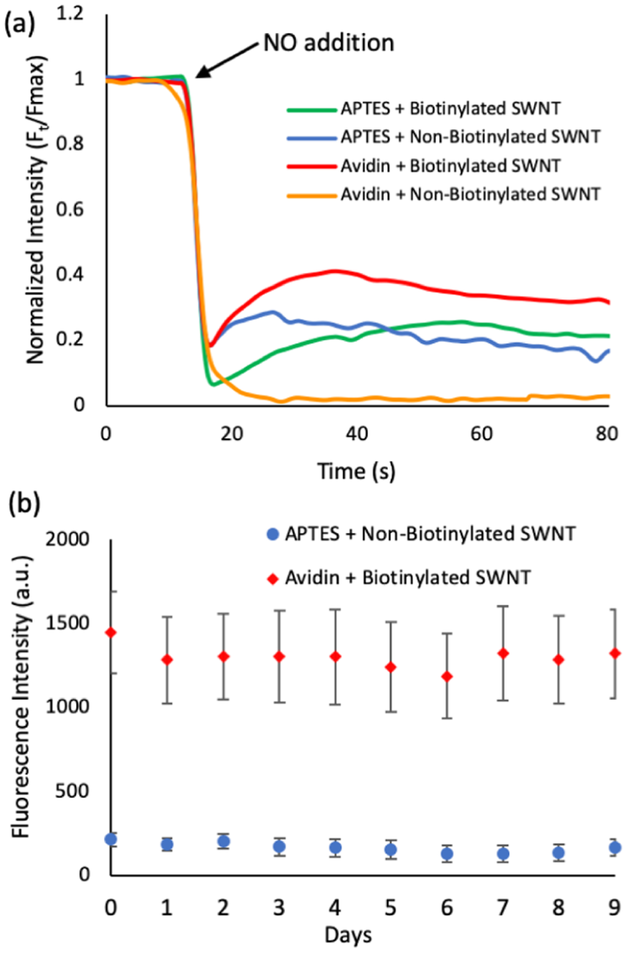
Ability of the sensor to react to NO and longevity of SWNT adhesion to the surface are both important aspects in the development of an extracellular platform. (a) Biotinylated and non-biotinylated SWNT (30 mg/L) was applied to APTES and avidin surfaces and quenched by 30 μM NO (final concentration) (n = 3). The initial fluorescence intensity for the samples is different, as displayed in Figure 4c. In an attempt to better compare the NO quenching reaction, we used a normalized intensity for all conditions, setting the initial intensity value to 100% and the other values for the specific sample were scaled to represent a percent of the initial fluorescence. Samples showed similar quenching results until reaching 75% quenching, indicating that the method of deposition had little impact on the initial sensor response. On average, avidin + biotinylated SWNT, avidin + non-biotinylated SWNT, APTES + biotinylated SWNT, and APTES + non-biotinylated SWNT required 4.06, 4.46, 3.72, and 3.84 s to go from the point of NO addition to 75% fluorescence quenching, lacking a statistical difference as determined by one-way ANOVA analysis with Tukey’s multiple comparison test. Variations in total quenching and recovery may indicate that other factors, such as sensor freedom of movement and concentration, play a role in sensor response. (b) Biotinylated SWNT and non-biotinylated SWNT (30 mg/L) were applied to avidin and APTES substrates respectively. Slides were stored in individual slide holders with 4 mL of phosphate-buffered saline (PBS), which was replaced every day. Fluorescence intensity values were tracked over the course of 10 days (n = 3, s = 5). The avidin + biotinylated SWNT sample was found to consistently outperform the APTES + non-biotinylated sample with more than triple its fluorescence intensity.
The purpose of the sensing platform is to allow for the detection of changes in extracellular analyte concentrations. In order for the platform to detect extracellular concentrations, it is essential that the sensors remain attached to the surface throughout the rinsing and media changing events associated with cell growth. Therefore, the attachment of the SWNT over multiple days and with multiple solution changes was analyzed for the current standard for SWNT deposition, APTES + nonbiotinylated SWNT, and the new avidin + biotinylated SWNT platform.
In order to simulate cell culture conditions, slides were prepared using 30 mg/L of SWNT and placed in individual slide holders with 4 mL of PBS, so that the surface was completely covered. Every day, the supernatant was completely removed and replaced with fresh PBS. We tracked the loss of SWNT from the surface of the platforms over the course of 10 days (including day 0) (Figure 5b). Fluorescence readings were collected as previously described and the average fluorescence calculated. Both the avidin + biotinylated SWNT and APTES + non-biotinylated SWNT samples demonstrated stability over the course of the study, maintaining 91.4 and 76.8% of their initial fluorescence, respectively. However, the avidin + biotinylated SWNT samples were found to maintain significantly more SWNT (p < 0.02) over the course of the study, more than three times the fluorescence of the APTES + non-biotinylated SWNT, indicating that the avidin + biotinylated SWNT deposition strategy can be used to significantly increase SWNT retention over long periods of time. This higher initial fluorescence intensity of the SWNT platform is essential for cellular studies because the sensor reacts to different NO concentrations with different degrees of fluorescence quenching. For cellular studies, in which low concentrations of NO are released by the cells, there will be a small change in SWNT fluorescence, which will be difficult to differentiate from the signal noise.
Cell Growth on Platforms.
The purpose of the sensing platform is to allow for the detection of extracellular NO concentrations. To prove the capabilities of the avidin + biotinylated SWNT platforms to function in vitro, the 10 day sensor fluorescence study was repeated with the platforms bathed in L-15 media and incubated at 37 °C. The platforms performed similar to the results observed in the PBS solution, with the fluorescence intensity maintained over the 10 day period (Figure 6a).
Figure 6.
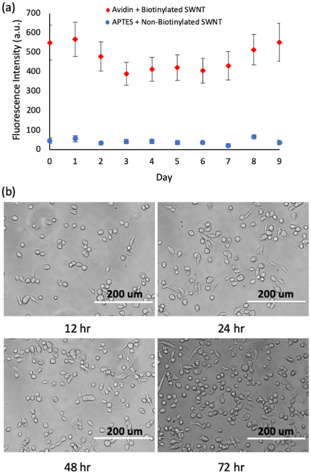
In vitro conditions are placed on the platforms to demonstrate their ability to maintain fluorescence intensity and support cell growth. (a) Biotinylated SWNT and non-biotinylated SWNT (30 mg/L) were applied to avidin and APTES substrates, respectively. Slides were stored in individual slide holders at 37 °C with 4 mL of L-15 media, which was replaced daily. Fluorescence intensity values were tracked over the course of 10 days (n = 3, s = 5). The avidin + biotinylated SWNT sample was found to consistently outperform the APTES + non-biotinylated sample with more than triple its fluorescence intensity. (b) Cell growth is shown for breast cancer cells (MDA MB 231) that were seeded on the sensor platforms. Images of cells were taken at 12, 24, 48, and 72 h time points, demonstrating cell growth over a three day time frame.
A preliminary study to prove the ability of cells to grow on the platform was performed over a 72 h period. The MDA MB 231 cells show attachment and proliferation when seeded on the avidin + biotinylated SWNT platform, as shown on Figure 6b.
CONCLUSIONS
This work highlights the first use of a covalently tethered avidin molecule for the deposition of biotinylated-SWNT on a glass surface. The biotinylation of SWNT by wrapping with biotinylated DNA was demonstrated and shown to act the same as non-biotinylated DNA-wrapped SWNT. A scheme for the derivatization of surfaces with a covalently linked avidin molecule was developed and characterized with a combination of contact angle and XPS spectra. Compared with a traditional method of SWNT deposition (APTES), the use of an avidin–biotin bond produced significant increases in SWNT retention at 30, 40, and 50 mg/L SWNT without altering the spatial distribution of the fluorescence on the platform. The improved platform maintained SWNT responsiveness to an analyte, and the platform demonstrated longevity under cell culture-like conditions.
The improved loading capacity demonstrated here can improve in vitro studies by decreasing laser intensity and exposure time needed to analyze samples, resulting in fewer laser induced side effects on the sample and decreased data acquisition time. The method can also be used with other DNA–SWNT sensors, leading to enhanced in vitro detection for a wide range of analytes.
MATERIALS AND METHODS
Fabrication of SWNT-Derivatized Substrates.
Figure 1 shows a schematic of the fabrication process used to create SWNT-immobilized surfaces. Slides were derivatized with SWNT via a 4-step process: slides were (1) immersed in piranha solution to generate hydroxyl groups, (2) transferred to a 3-GPTMS solution followed by oven curing to generate a 3-GPTMS network on the surface, (3) exposed to avidin, allowing the primary amines to covalently bind with the epoxide rings of 3-GPTMS, and (4) exposed to (a) nonbiotinylated SWNT, where the negatively charged DNA backbone interacts with the positively charged avidin protein or (b) biotinylated SWNT, where avidin–biotin binding may take place in conjunction with any electrostatic interactions. Figure 1 also shows the fabrication process for the production of SWNT-immobilized surfaces, utilizing a substrate. Slides were derivatized via a 3-step process: slides were (1) immersed in piranha solution to generate hydroxyl groups, (2) transferred to an APTES solution followed by oven curing to generate an APTES network on the surface, and (3) exposed to SWNT, where the partially negatively charged DNA backbone interacts electrostatically with the aminopropyl head of APTES.
Dispersion of SWNT with DNA Oligos.
SWNT were dispersed with DNA oligos similar to the methods previously described.11,42 Briefly, CoMoCAT 6,5 SWNT (Sigma) were wrapped with either d(AT)15 single stranded DNA (termed (AT)15 throughout the rest of the paper) alone or a 1:1 volumetric ratio of 5′-biotinylated (AT)15 and (AT)15 (Integrated DNA Technologies). Wrapping procedures were identical regardless of the presence or absence of biotinylated (AT)15. SWNT and DNA were combined in a 2:1 mass ratio in nanopure water. The SWNT, DNA, and water mixture was then bath sonicated for 10 min, followed by ultrasonic tip sonication (QSonica Q125 Sonicator) in an ice water bath with a 3 mm probe tip in two 20 min intervals at approximately 4 W. The SWNT suspension was then centrifuged for two 90 min sessions at 16100 RCF (Beckman Coulter Microfuge 16). The top 80% of the SWNT supernatant was collected after each centrifugation and the pellet was discarded to remove unwrapped SWNT bundles. SWNT concentration was obtained via UV–vis spectroscopy (Beckman Coulter, DU 730) and diluted to appropriate concentrations.11 SWNT was stored at 4 °C for up to 1 month.
The 1:1 volumetric ratio of 5′-biotinylated (AT)15- and (AT)15-wrapped SWNT will be referred to as biotinylated SWNT throughout the paper. The (AT)15-wrapped SWNT will be referred to as non-biotinylated SWNT throughout the paper.
Generation of Avidin–Biotin–SWNT-Derivatized Surfaces.
Avidin derivatized slides were generated with a protocol adapted from one previously described by Schena and Yang et al.43,44 Briefly, water-white glass microscope slides (Corning) were treated with a 70% sulfuric acid/30% hydrogen peroxide (piranha) solution (Fisher) for 16 h. Slides where then washed with excess amounts of nanopure water, rinsed 3 times in ethanol, and dried by centrifugation at 1600g for 1 min before being transferred to a solution consisting of 95% ethanol, 16 mM acetic acid (Honeywell), and 1% (3-glycidopropyl)-trimethoxysilane (Sigma) for 24 h. Slides were then rinsed with ethanol 3 times and cured in a 150 °C oven for 3 h. The slides were allowed to return to room temperature, rinsed with ethanol 3 times, and allowed to dry under ambient conditions. Avidin (60 μL of 1 mg/mL)(Sigma) in 10 mM NaHCO3 was then added to the surface of the slide, covered with a plastic coverslip (22 mm × 22 mm), and allowed to incubate overnight in a 37 °C incubator (HERAcell 150i). Coverslips were removed and slides rinsed with excess nanopure water. Slides were then blown dry under an argon stream. Aspartic acid (60 μL, 2 mM)in 0.5 M NaHCO3 buffer was added to the surface and covered with a coverslip for 30 min to quench any remaining epoxide groups. Coverslips were removed and slides washed with excess nanopure water and blown dry with an argon stream. biotinylated or non-biotinylated SWNT (60 μL) was then added to the surface at the desired concentration and allowed to incubate for 24 h in a 37 °C incubator. Coverslips were removed and slides were washed with excess amounts of nanopure water. Slides were stored in custom made individual holders and used after a 2 h equilibrium period.
Generating ATPES-Derivatized Surfaces.
APTES slides were generated similarly to avidin-derivatized slides. Briefly, microscope slides were treated with piranha for 16 h. Slides where washed with excess amounts of nanopure water, rinsed 3 times in ethanol, and dried under centrifugation before being transferred to a solution consisting of 95% ethanol, 16 mM acetic acid, and 1% APTES for 24 h. Slides were then rinsed with ethanol and cured at 150 °C for 3 h. Following cooling, slides were rinsed once more with ethanol and allowed to dry. SWNT (60 μL) at the desired concentration was then added and covered by a coverslip. Slides were allowed to incubate with SWNT for 24 h in a 37 °C incubator. Following incubation, slides were washed with excess amounts of nanopure water, stored in individual holders, and used after a 2 h equilibrium period.
XPS Measurements.
XPS measurements were taken using the K-alpha+ XPS/UPS system (Thermo) with an Al Kα micro-focused monochromator X-ray source. Backgrounds were removed, atomic percent calculated, and peaks identified using Avantage software.
Contact Angle Measurements.
Static contact angle images were captured using an Attension Theta optical tensiometer (Biolin Scientific) and analyzed using OneAttension Software. A 1 μL drop of double distilled water was used in all cases. Droplets were analyzed for 5 s and the contact angle achieved at 3 s was used, allowing for settling effects.
Generating NO Solution.
NO solution was generated using a method similar to the one previously described.11 Briefly, 10 mL of 1× PBS (HyClone) was added to a 10 mL round bottom flask and sealed with a sleeve stopper. Two needles were inserted through the sleeve stopper to provide an inlet and outlet for gas flow. Argon gas (Matheson Tri-Gas, Inc., 99.999%) was introduced to the PBS to remove any dissolved oxygen for 20 min. The NO gas (Matheson Tri-Gas, Inc., 99%) was then introduced to the buffer for an additional 20 min. Needles were then removed and the NO solution kept sealed. NO dilutions were achieved by mixing the NO stock with pre-purged PBS buffer (argon 20 min) in a sealed air-purged 5 mL round bottom flask (argon 20 min). The NO solution was always added to samples using a gas tight syringe directly over the area of interest.
Horseradish Peroxidase Assay.
NO concentration was quantified using a horseradish peroxidase (HRP) assay as previously described.45 Briefly, NO was added to HRP (Thermo) for a final concentration of 1.36 μM HRP. The absorbance was collected from 300 to 650 nm using a UV–vis spectrometer (Beckman Coulter DU 730) with a step size of 1 nm and the underlying HRP spectra removed. The second order derivative was determined using an in-house written MATLAB program. Derivative spectra were smoothed using a Savitsky–Golay algorithm (order = 3, frame length = 21). The NO concentration was then calculated using the difference between the peak at 210 nm and the valley at 240 nm.
Fluorescence Measurements and Microscopy.
Measurements of the SWNT fluorescence intensity and spectrum were determined with a custom built nIR microscope (Photon Etc.). The setup is similar to the one previously published46 but is an upright instead of inverted Nikon. Briefly, SWNT samples were excited by a 561 nm laser, the resulting emission was then passed through a volume Bragg grating twice to reduce bandwidth and limit wavelength. The sample intensity was recorded across wavelengths to generate a hyperspectral cube. The cube was rectified to generate images at the desired wavelengths. Pixel-by-pixel intensity information was captured using an InGaAs camera (Xenics, Xeva-1.7–320 TE3).
When only 990 nm fluorescence intensity was desired, a 990 nm band pass filter (Thor Labs) was used rather than the volumetric Bragg grating system.
Spectral properties of SWNT in the solution were determined using 200 μL of samples at 30 mg/L. Hyperspectral cubes were collected from 900 to 1080 nm using a step size of 1 nm and an exposure time of 200 ms.
Quenching of SWNT in solution was determined using 200 μL of samples at 30 mg/L. The 990 nm band pass filter was used to examine the response of the sensors to NO addition. The NO solution was added to SWNT samples at a final concentration of 30 μM and quenching was recorded with an exposure time of 200 ms. Quenching curves were collected, smoothed using the MATLAB’s Gaussian filter (frame length = 20), and aggregated.
When performing fluorescence intensity measurements on immobilized SWNT samples, the 990 nm band pass filter was used. Fluorescence readings were collected at 5 locations across the surface of the treated area (Figure S1), and three slides were sampled per condition in order to determine an average fluorescence per condition (n = 3, s = 5).
The relationship between the SWNT concentration and loading performance was investigated by applying SWNT concentrations of 10, 20, 30, 40, and 50 mg/L to their respective surfaces. Fluorescence intensity values were collected as previously stated and the average fluorescence values calculated.
The fluorescence response of immobilized sensors to 30 μM NO addition (final concentration) was measured using the 990 nm band pass filter. A 500 ms exposure time was used to collect the data. The data were then normalized, smoothed using a MATLAB’s Gaussian filter (frame length = 10), and aggregated.
For long-term sensor stability, slides were prepared using 30 mg/L of SWNT and placed in individual slide holders with 4 mL of PBS, so that the surface was completely covered. Slides were stored covered at room temperature. Every day, the supernatant was completely removed and replaced with fresh PBS. We tracked the loss of SWNT from the surface of the various platforms over the course of 10 days (including day 0). Fluorescence readings were collected as previously described and the average fluorescence was calculated (n = 3 s = 5).
To simulate long-term fluorescence in cell culture conditions, slides were prepared and analyzed as above, except L-15 media was used to incubate the slides. The slides were also stored at 37 °C for the duration of the 10 day study.
To show the ability of cells to grow on the platforms, we seeded MDA MB 231 cells, grown in complete L-15 media, and incubated at 37°C. The cells were imaged at 12, 24, 48, and 72 h time points.
Supplementary Material
ACKNOWLEDGMENTS
The authors would like to thank Yufeng Ge for his guidance, comments, and support. We would also like to thank Balamurugan Balasubramanian and Steve Morin for their assistance with surface characterization and Albert Nguyen and Amy Mantz for their thoughtful comments and suggestions.
Funding
The research was supported by a NIH COBRE grant (P30 GM127200) and the National Science Foundation EPSCoR Cooperative Agreement OIA-1557417.
ABBREVIATIONS
- SWNT
single-walled carbon nanotubes
- NO
nitric oxide
- H2O2
hydrogen peroxide
- APTES
(3-aminopropyl)triethoxysilane
- 3-GPTMS
3-glycidoxypropyltrimethoxysilane
- HRP
horseradish peroxidase
- fwhm
full width half maximum
- XPS
X-ray photoelectron spectroscopy
Footnotes
Supporting Information
The Supporting Information is available free of charge at https://pubs.acs.org/doi/10.1021/acsanm.0c01998.
Atomic percentages for each step of the platform derivation, fwhm values for both biotinylated and non-biotinylated SWNT, schematic of the sample collection scheme that was used to collect fluorescence data, contact angle image for the plain glass slide prior to the derivatization steps, contact angle images and XPS data for the APTES treated slides, and second method of analyzing fluorescence smoothness (2D discrete wavelet decomposition) (PDF)
The authors declare no competing financial interest.
Complete contact information is available at: https://pubs.acs.org/10.1021/acsanm.0c01998
REFERENCES
- (1).Schieber M; Chandel NS ROS function in redox signaling and oxidative stress. Curr. Biol 2014, 24, R453–R462. [DOI] [PMC free article] [PubMed] [Google Scholar]
- (2).Dinger ME; Mercer TR; Mattick JS RNAs as extracellular signaling molecules. J. Mol. Endocrinol 2008, 40, 151–159. [DOI] [PubMed] [Google Scholar]
- (3).Fields R; Stevens B ATP: an extracellular signaling molecule between neurons and glia. Trends Neurosci. 2000, 23, 625–633. [DOI] [PubMed] [Google Scholar]
- (4).Hankenson KD; Gagne K; Shaughnessy M Extracellular signaling molecules to promote fracture healing and bone regeneration. Adv. Drug Delivery Rev 2015, 94, 3–12. [DOI] [PubMed] [Google Scholar]
- (5).Akamizu T; Shinomiya T; Irako T; Fukunaga M; Nakai Y; Nakai Y; Kangawa K Separate measurement of plasma levels of acylated and desacyl ghrelin in healthy subjects using a new direct ELISA assay. J. Clin. Endocrinol. Metab 2005, 90, 6–9. [DOI] [PubMed] [Google Scholar]
- (6).Ida N; Hartmann T; Pantel J; Schröder J; Zerfass R; Förstl H; Sandbrink R; Masters CL; Beyreuther K Analysis of heterogeneous βA4 peptides in human cerebrospinal fluid and blood by a newly developed sensitive Western blot assay. J. Biol. Chem 1996, 271, 22908–22914. [DOI] [PubMed] [Google Scholar]
- (7).Sinkala E; Sollier-Christen E; Renier C; Rosas-Canyelles E; Che J; Heirich K; Duncombe T; Vlassakis J; Yamauchi K; Huang H; Jeffrey SS; Herr AE Profiling protein expression in circulating tumour cells using microfluidic western blotting. Nat. Commun 2017, 8, 14622. [DOI] [PMC free article] [PubMed] [Google Scholar]
- (8).Gelsinger SL; Smith AM; Jones CM; Heinrichs AJ Technical note: Comparison of radial immunodiffusion and ELISA for quantification of bovine immunoglobulin G in colostrum and plasma. J. Dairy Sci 2015, 98, 4084–4089. [DOI] [PubMed] [Google Scholar]
- (9).Groseclose MR; Andersson M; Hardesty WM; Caprioli RM Identification of proteins directly from tissue:in situ tryptic digestions coupled with imaging mass spectrometry. J. Mass Spectrom 2007, 42, 254–262. [DOI] [PubMed] [Google Scholar]
- (10).Li CM; Zang J; Zhan D; Chen W; Sun CQ; Teo AL; Chua YT; Lee VS; Moochhala SM Electrochemical detection of nitric oxide on a SWCNT/RTIL composite gel microelectrode. Electroanalysis 2006, 18, 713–718. [Google Scholar]
- (11).Zhang J; Boghossian AA; Barone PW; Rwei A; Kim J; Lin D; Heller DA; Hilmer AJ; Nair N; Reuel NF; Strano MS Single molecule detection of nitric oxide enabled by d(AT)15 DNA adsorbed to near infrared fluorescent single-walled carbon nanotubes. J. Am. Chem. Soc 2011, 133, 567–581. [DOI] [PubMed] [Google Scholar]
- (12).Jin H; Heller DA; Kalbacova M; Kim J-H; Zhang J; Boghossian AA; Maheshri N; Strano MS Detection of single-molecule H2O2 signalling from epidermal growth factor receptor using fluorescent single-walled carbon nanotubes. Nat. Nanotechnol 2010, 5, 302. [DOI] [PMC free article] [PubMed] [Google Scholar]
- (13).Barone PW; Parker RS; Strano MS In vivo fluorescence detection of glucose using a single-walled carbon nanotube optical sensor: design, fluorophore properties, advantages, and disadvantages. Anal. Chem 2005, 77, 7556–7562. [DOI] [PubMed] [Google Scholar]
- (14).Kruss S; Salem DP; Vuković L; Lima B; Vander Ende E; Boyden ES; Strano MS High-resolution imaging of cellular dopamine efflux using a fluorescent nanosensor array. Proc. Natl. Acad. Sci. U.S.A 2017, 114, 1789–1794. [DOI] [PMC free article] [PubMed] [Google Scholar]
- (15).Landry MP; Ando H; Chen AY; Cao J; Kottadiel VI; Chio L; Yang D; Dong J; Lu TK; Strano MS Single-molecule detection of protein efflux from microorganisms using fluorescent single-walled carbon nanotube sensor arrays. Nat. Nanotechnol 2017, 12, 368. [DOI] [PMC free article] [PubMed] [Google Scholar]
- (16).Beyene AG; Delevich K; Del Bonis-O’Donnell JT; Piekarski DJ; Lin WC; Thomas AW; Yang SJ; Kosillo P; Yang D; Prounis GS; Wilbrecht L; Landry MP Imaging striatal dopamine release using a nongenetically encoded near infrared fluorescent catecholamine nanosensor. Sci. Adv 2019, 5, No. eaaw3108. [DOI] [PMC free article] [PubMed] [Google Scholar]
- (17).Jeong S; Yang D; Beyene AG; Del Bonis-O’Donnell JT; Gest AMM; Navarro N; Sun X; Landry MP High Throughput Evolution of Near Infrared Serotonin Nanosensors. Sci. Adv 2019, 5, No. eaay3771. [DOI] [PMC free article] [PubMed] [Google Scholar]
- (18).Jena PV; Roxbury D; Galassi TV; Akkari L; Horoszko CP; Iaea DB; Budhatholi-Uprety J; Pipalia N; Haka AS; Harvey JD; Mittal J; Maxfield FR; Joyce JA; Heller DA A carbon nanotube optical reporter maps endolysosomal lipid flux. ACS Nano 2017, 11, 10689–10703. [DOI] [PMC free article] [PubMed] [Google Scholar]
- (19).Galassi TV; Jena PV; Shah J; Ao G; Molitor E; Bram Y; Frankel A; Park J; Jessurun J; Ory DS; Haimovitz-Friedman A; Roxbury D; Mittal J; Zheng M; Schwartz RE; Heller DA An optical nanoreporter of endolysosomal lipid accumulation reveals enduring effects of diet on hepatic macrophages in vivo. Sci. Transl. Med 2018, 10, No. eaar2680. [DOI] [PMC free article] [PubMed] [Google Scholar]
- (20).Harvey JD; Jena PV; Baker HA; Zerze GH; Williams RM; Galassi TV; Roxbury E; Mittal J; Heller DA A carbon nanotube reporter of microRNA hybridization events in vivo. Nat. Biomed. Eng 2017, 1, 0041. [DOI] [PMC free article] [PubMed] [Google Scholar]
- (21).Barone PW; Baik S; Heller DA; Strano MS Near-infrared optical sensors based on single-walled carbon nanotubes. Nat. Mater 2005, 4, 86. [DOI] [PubMed] [Google Scholar]
- (22).O’connell MJ; Bachilo SM; Huffman CB; Moore VC; Strano MS; Haroz EH; Rialon KL; Boul PJ; Noon WH; Kittrell C; Ma J; Hauge RH; Weisman RB; Smalley RE Band gap fluorescence from individual single-walled carbon nanotubes. Science 2002, 297, 593–596. [DOI] [PubMed] [Google Scholar]
- (23).Bachilo SM; Strano MS; Kittrell C; Hauge RH; Smalley RE; Weisman RB Structure-assigned optical spectra of single-walled carbon nanotubes. Science 2002, 298, 2361–2366. [DOI] [PubMed] [Google Scholar]
- (24).Hartschuh A; Pedrosa HN; Novotny L; Krauss TD Simultaneous fluorescence and Raman scattering from single carbon nanotubes. Science 2003, 301, 1354–1356. [DOI] [PubMed] [Google Scholar]
- (25).McCartney LJ; Pickup JC; Rolinski OJ; Birch DJS Near-infrared fluorescence lifetime assay for serum glucose based on allophycocyanin-labeled concanavalin A. Anal. Biochem 2001, 292, 216–221. [DOI] [PubMed] [Google Scholar]
- (26).Wray S; Cope M; Delpy DT; Wyatt JS; Reynolds EOR Characterization of the near infrared absorption spectra of cytochrome aa3 and haemoglobin for the non-invasive monitoring of cerebral oxygenation. Biochim. Biophys. Acta, Bioenerg 1988, 933, 184–192. [DOI] [PubMed] [Google Scholar]
- (27).Klonis N; Quazi NH; Deady LW; Hughes AB; Tilley L Characterization of a series of far-red-absorbing thiobarbituric acid oxonol derivatives as fluorescent probes for biological applications. Anal. Biochem 2003, 317, 47–58. [DOI] [PubMed] [Google Scholar]
- (28).Kim S; Lim YT; Soltesz EG; De Grand AM; Lee J; Nakayama A; Parker JA; Mihaljevic T; Laurence RG; Dor DM; Cohn LH; Bawendi MG; Frangioni JV Near-infrared fluorescent type II quantum dots for sentinel lymph node mapping. Nat. Biotechnol 2004, 22, 93. [DOI] [PMC free article] [PubMed] [Google Scholar]
- (29).Frangioni J In vivo near-infrared fluorescence imaging. Curr. Opin. Chem. Biol 2003, 7, 626–634. [DOI] [PubMed] [Google Scholar]
- (30).Heller DA; Jin H; Martinez BM; Patel D; Miller BM; Yeung T-K; Jena PV; Höbartner C; Ha T; Silverman SK; Strano MS Multimodal optical sensing and analyte specificity using single-walled carbon nanotubes. Nat. Nanotechnol 2009, 4, 114. [DOI] [PubMed] [Google Scholar]
- (31).Kruss S; Landry MP; Vander Ende E; Lima BMA; Reuel NF; Zhang J; Nelson J; Mu B; Hilmer A; Strano M Neurotransmitter detection using corona phase molecular recognition on fluorescent single-walled carbon nanotube sensors. J. Am. Chem. Soc 2014, 136, 713–724. [DOI] [PubMed] [Google Scholar]
- (32).Frostell C; Fratacci MD; Wain JC; Jones R; Zapol WM Inhaled nitric oxide. A selective pulmonary vasodilator reversing hypoxic pulmonary vasoconstriction. Circulation 1991, 83, 2038–2047. [DOI] [PubMed] [Google Scholar]
- (33).Bogdan C Nitric oxide synthase in innate and adaptive immunity: an update. Trends Immunol. 2015, 36, 161–178. [DOI] [PubMed] [Google Scholar]
- (34).Cossenza M; Socodato R; Portugal CC; Domith ICL; Gladulich LFH; Encarnaҫão TG; Calaza KC; Mendoncҫa HR; Campello-Costa P; Paes-de-Carvalho R Nitric Oxide in the Nervous System: Biochemical, Developmental, and Neurobiological Aspects. Vitam. Horm 2014, 96, 79–125. [DOI] [PubMed] [Google Scholar]
- (35).Wink D; Mitchell JB Nitric oxide and cancer: an introduction. Free Radical Biol. Med 2003, 34, 951–954. [DOI] [PubMed] [Google Scholar]
- (36).Wink D; Vodovotz Y; Laval J; Laval F; Dewhirst MW; Mitchell JB The multifaceted roles of nitric oxide in cancer. Carcinogenesis 1998, 19, 711–721. [DOI] [PubMed] [Google Scholar]
- (37).Lancaster JR; Xie K Tumors Face NO Problems?: Figure 1. Cancer Res. 2006, 66, 6459–6462. [DOI] [PubMed] [Google Scholar]
- (38).Hofseth L; Hussain SP; Wogan GN; Harris CC Nitric oxide in cancer and chemoprevention. Free Radical Biol. Med 2003, 34, 955–968. [DOI] [PubMed] [Google Scholar]
- (39).Hofseth LJ Nitric oxide as a target of complementary and alternative medicines to prevent and treat inflammation and cancer. Cancer Lett. 2008, 268, 10–30. [DOI] [PMC free article] [PubMed] [Google Scholar]
- (40).Xu W; Liu LZ; Loizidou M; Ahmed M; Charles IG The role of nitric oxide in cancer. Cell Res. 2002, 12, 311–320. [DOI] [PubMed] [Google Scholar]
- (41).Choudhari SK; Chaudhary M; Bagde S; Gadbail AR; Joshi V Nitric oxide and cancer: a review. World J. Surg. Oncol 2013, 11, 118. [DOI] [PMC free article] [PubMed] [Google Scholar]
- (42).Zheng M; Jagota A; Semke ED; Diner BA; Mclean RS; Lustig SR; Richardson RE; Tassi NG DNA-assisted dispersion and separation of carbon nanotubes. Nat. Mater 2003, 2, 338. [DOI] [PubMed] [Google Scholar]
- (43).Yang Z; Xie Z; Liu H; Yan F; Ju H Streptavidin-Functionalized Three-Dimensional Ordered Nanoporous Silica Film for Highly Efficient Chemiluminescent Immunosensing. Adv. Funct. Mater 2008, 18, 3991–3998. [Google Scholar]
- (44).Schena M Protein Microarrays; Jones & Bartlett Learning, 2005. [Google Scholar]
- (45).Qiang L; Zhou J Determination of nitric oxide using horseradish peroxidase by UV second-order derivative spectrometry. Anal. Sci 2009, 25, 1467–1470. [DOI] [PubMed] [Google Scholar]
- (46).Roxbury D; Jena PV; Williams RM; Enyedi B; Niethammer P; Marcet S; Verhaegen M; Blais-Ouellette S; Heller DA Hyperspectral microscopy of near-infrared fluorescence enables 17-chirality carbon nanotube imaging. Sci. Rep 2015, 5, 14167. [DOI] [PMC free article] [PubMed] [Google Scholar]
- (47).Sumner AL; Menke EJ; Dubowski Y; Newberg JT; Penner RM; Hemminger JC; Wingen LM; Brauers T; Finlayson-Pitts BJ The nature of water on surfaces of laboratory systems and implications for heterogeneous chemistry in the troposphere. Phys. Chem. Chem. Phys 2004, 6, 604–613. [Google Scholar]
- (48).Eske LD; Galipeau DW Characterization of SiO2 surface treatments using AFM, contact angles and a novel dewpoint technique. Colloids Surf., A 1999, 154, 33–51. [Google Scholar]
- (49).Wong AKY; Krull UJ Surface characterization of 3-glycidoxypropyltrimethoxysilane films on silicon-based substrates. Anal. Bioanal. Chem 2005, 383, 187–200. [DOI] [PubMed] [Google Scholar]
- (50).Hofferber EM; Stapleton JA; Adams J; Kuss M; Duan B; Iverson NM Implantable Nanotube Sensor Platform for Rapid Analyte Detection. Macromol. Biosci 2019, 19, 1800469. [DOI] [PMC free article] [PubMed] [Google Scholar]
- (51).Iverson NM; Barone PW; Shandell M; Trudel LJ; Sen S; Sen F; Ivanov V; Atolia E; Farias E; McNicholas TP; Reuel N; Parry NMA; Wogan GN; Strano MS In vivo biosensing via tissue-localizable near-infrared-fluorescent single-walled carbon nanotubes. Nat. Nanotechnol 2013, 8, 873–880. [DOI] [PMC free article] [PubMed] [Google Scholar]
Associated Data
This section collects any data citations, data availability statements, or supplementary materials included in this article.