Graphical Abstract
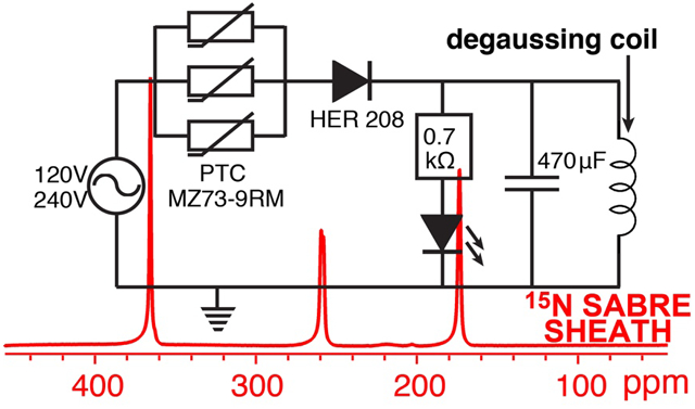
We report on the inexpensive ($80) custom electronics for efficient robust and fast degaussing of mu-metal shields for use in parahydrogen induced polarization experiments. The degaussing process is fully automated and can be performed in ~2 seconds resulting in residual magnetic field of <20 nT. The utility of this device is demonstrated for 15N hyperpolarization of [15N3]metronidazole below 1 microtesla. The reported electronics will be of practical use to those working in the field of parahydrogen utilizing both hydrogenative approaches for magnetic field cycling and non-hydrogenative approaches employing sub-microtesla magnetic fields to create level anti-crossing for polarization transfer from parahydrogen-derived nascent protons to the heteronucleus.
Keywords: parahydrogen, hyperpolarization, magnetic shield, metronidazole, degaussing
Introduction
NMR techniques have inherent low sensitivity due to low nuclear spin polarization (P) or the degree of alignment of nuclear spins with applied magnetic field. However, P can be transiently enhanced by several orders of magnitude via NMR hyperpolarization techniques.[1–5] Corresponding gains in signal-to-noise ratio (SNR) of hyperpolarized (HP) dilute biologically compatible compounds enable new applications: most notably, in vivo tracking of biological processes.[6–9] Parahydrogen Induced Polarization (PHIP) allows for efficient and low-cost hyperpolarization of nuclear spins using parahydrogen (p-H2).[10, 11] PHIP was pioneered in 1986,[10] and the utility of p-H2-induced hyperpolarized (HP) compounds for in vivo imaging applications was demonstrated in 2001.[6] Despite substantial developments over the past decade,[12–14] this hyperpolarization technique is certainly lagging behind compared to more established Spin Exchange Optical Pumping (SEOP)[15] and dissolution Dynamic Nuclear Polarization (d-DNP),[2, 4] which have numerous completed and pending clinical trials.[16–18] It is our opinion that successful PHIP clinical translation requires robust hyperpolarization equipment support similar to that of SEOP and d-DNP techniques. The work reported here is aimed to enable the PHIP community with an inexpensive tool to improve the robustness and precision of PHIP hyperpolarization equipment.
In PHIP, once the symmetry of nascent parahydrogen-derived protons is broken, the spin order can be transferred to X-nucleus (anything but protons, e.g., 13C or 15N) via spin-spin couplings through the use of nanotesla magnetic fields.[19–21] The process of polarization transfer requires precise manipulation of static magnetic fields in the range of 10–1000 nT, where spin level anti-crossings (LAC) are created between nascent p-H2-derived protons and to-be-hyperpolarized nucleus.[22]
In hydrogenative PHIP, p-H2 is first added to the unsaturated precursor in a pairwise manner. Next, the magnetic field is decreased below BLAC (ca. 100 nT). Finally, the adiabatic passage via BLAC enables efficient polarization transfer to X-nucleus, Figure 1b.[23] This approach has been called Magnetic Field Cycling (MFC)[19] or Sweeping (MFS).[24] P13C of up to 21% has been obtained[19] and P13C of 5–10% has been demonstrated for [1-13C]pyruvate,[25–27] the leading 13C HP contrast agent currently under evaluation in many clinical trials.
Figure 1.
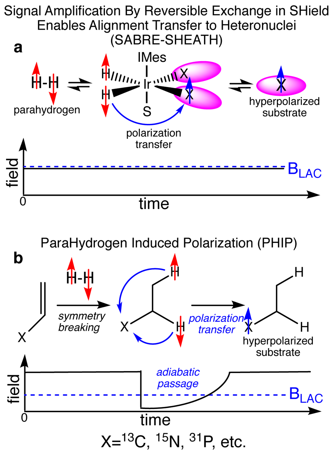
Schematics of SABRE-SHEATH and PHIP MFC hyperpolarization techniques.
The Non-hydrogenative PHIP variant called Signal Amplification by Reversible Exchange (SABRE) employs the process of simultaneous chemical exchange of p-H2 and to-be-hyperpolarized molecule on a metal center.[28–31] The polarization transfer complex (PTC) containing p-H2-derived hydrides and substrate containing X-nucleus (15N,[32] 31P,[33] 13C,[21, 34, 35] etc.) is transiently formed. The efficient polarization transfer from p-H2-derived hydrides to X-nucleus is achieved via LAC creation by matching i) the spin-spin coupling between hydride proton and X-nucleus, ii) difference of gyromagnetic ratios between hydride protons and X-nucleus, iii) and applied static magnetic field BLAC. This condition is fulfilled at magnetic fields in the range of 0.2–1 μT,[20, 36], and this approach was called SABRE-SHEATH (SABRE in SHield Enables Alignment Transfer to Heteronuclei). BLAC is applied throughout the SABRE-SHEATH process (Figure 1a) although alternative pulsed schemes have been developed too.[37] P15N over 50%[38–40] have been demonstrated using SABRE-SHEATH for FDA-approved drug metronidazole, which can be potentially employed for hypoxia sensing applications. 13C polarization exceeding 1% has been demonstrated for 13C-labeled pyruvate.[41, 42]
The Earth’s field is approximately two orders of magnitude stronger than BLAC for PHIP and SABRE polarization of X-nucleus. In practice, multi-layered mu-metal shields represent a convenient and cost-effective approach (ca. $1k–5k) to attenuate the Earth’s field nominally by three orders of magnitude. As a result, the desired nanotesla magnetic field can be obtained. However, mu-metal shields are susceptible to magnetization and can retain a substantial degree of residual magnetization: sometimes in excess of 1,000 nT. While a small (0.1–0.2 μT) residual field can be simply treated as an offset in SABRE-SHEATH or PHIP MFC, the BLAC calibration is required to account for residual static field of the magnetic shield. This is highly inconvenient at best, and it makes the daily equipment operation non-trivial.
Here, we report on simple circuitry to perform fast (2 seconds) automated degaussing procedure of mu-metal shields of up to 27 in. (~0.69 meter) of height with reproducible residual magnetization less than 20 nT. The degaussing process applies alternating electric current with adiabatic decay achieved by thermistors. We employ the process of 15N SABRE-SHEATH hyperpolarization of [15N3]metronidazole as a test bed to demonstrate the utility of the reported electronics circuit.
Materials and Methods
The circuit (Figure 2a) employs 120–240 VAC power mains as a source of alternating current. Three thermistors (9 Ω each) are placed in parallel to boost the current carrying capacity of the circuit during the charging phase. When the switch is activated, the “charging” phase is initiated. During this phase, the current increases causing the thermistors to warm up, thus resulting in an increase of their resistance by ~4–5 orders of magnitude. As a result, in a few hundred milliseconds, the current begins to decay adiabatically due to increasing resistance of the thermistors. The current decay is completed in less than 2 seconds, i.e. the thermistors ensure the mains power is no longer supplied after this relatively short period of time. In practice, we employed a push-button switch, which is un-pressed after approximately 1 second. A diode is added in series with resistors to ensure the flow of power from the mains to the degaussing inductor is unidirectional. The diode output is connected to capacitor (470 μF) and degaussing inductor, see Figure 2. In practice, we have successfully tested a wide range of degaussing inductors made in house (40.4 mH) and also supplied by the vendor for the following shields ZG-203 (4.8 mH), ZG-206 (18.1 mH), ZG-209 (105.8 mH), Magnetic Shield Corp., Bensenville, IL USA. We have also added a LED indicator to inform the user that the circuit was truly energized (light ON) and that the process was completed (dimming light). An ~0.7 kΩ resistor is added in series to protect the LED and to also modulate the decay rate of the electromagnetic field in the LC circuit. The complete list of part numbers, manufacturers’, vendors’ information, and technical drawings can be found in Supporting Information (SI). The cost of construction was $73 – note that some components were purchased in bulk.
Figure 2.
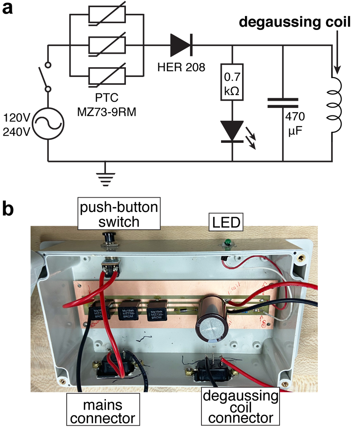
a) Schematics of automated degaussing circuit; b) photograph of the assembled circuit in plastic electric enclosure.
15N SABRE-SHEATH experiments were performed as described previously.[43–45] Briefly, Ir-IMes pre-catalyst[46] and [15N3]metronidazole were dissolved in CD3OD. The prepared 0.6 mL solution contained approximately 2 mM pre-catalyst and 40 mM [15N3]metronidazole. The solution was placed in an economy 5 mm NMR tube jacketed with 0.25 in. (~6.35 mm) OD Teflon extension. The solution was then purged with ultra-high purity argon gas for approximately 2 minutes before connecting it to our p-H2 bubbling setup via Teflon extension described in Figure 3 and Figure S1. Once the tube was connected to the manifold, the catalyst was activated for approximately 1 h using 20 standard cubic centimetres per minute (sccm) flow rate of p-H2 (~98%[47]) at 100 PSI (~690 kPa) overpressure. After catalyst activation, the formation of the polarization transfer complex (PTC) allows for efficient polarization transfer of nuclear spin polarization from p-H2-derived hydrides to 15N nuclei in [15N3]metronidazole. The details of spin-relayed polarization transfer to all three 15N sites are thoroughly reviewed elsewhere.[43–45] For SABRE-SHEATH hyperpolarization, we have employed 70 sccm flow rate for p-H2 bubbling and ZG-203 shield equipped with degaussing solenoid coil. The coil was connected to the degaussing circuit shown in Figure 2, and degaussing was performed using 120 VAC mains. The degaussing circuit was then disconnected and the RF solenoid coil was connected to 5 VDC power supply and current attenuation resistor bank. A residual field of less than 20 nT was measured repeatedly by a three-axis fluxgate magnetometer (Bartington Instruments, Oxford, U.K.) with 10 nT resolution.
Figure 3.
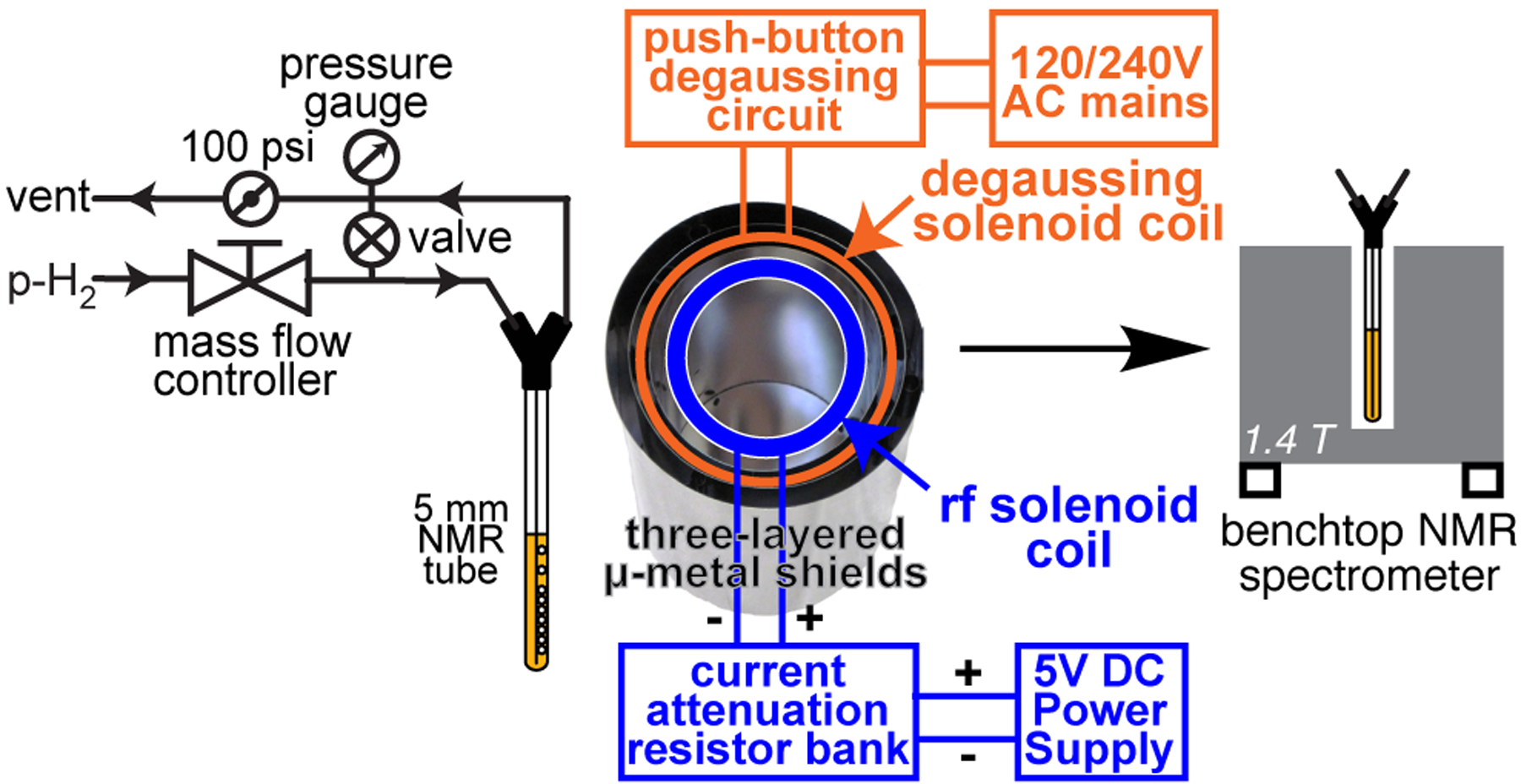
Schematic of experimental setup.
For 15N SABRE-SHEATH experiments, p-H2 was bubbled in the shield at BLAC (created by the RF solenoid inside the shield) for ~1 min at room temperature, 70 sccm and 100 PSI (690 kPa) overpressure. Next, p-H2 flow was ceased via opening the bypass valve, and the sample was quickly transferred for 15N detection in 1.4 T bench-top NMR spectrometer (Nanalysis, Canada). The total delay from p-H2 cessation to 15N NMR acquisition was less than 5 seconds. 15N signal enhancement and polarization levels were computed by employing external signal reference (12.4 M [15N]pyridine, Figure 4b) as described in detail previously.[43]
Figure 4.
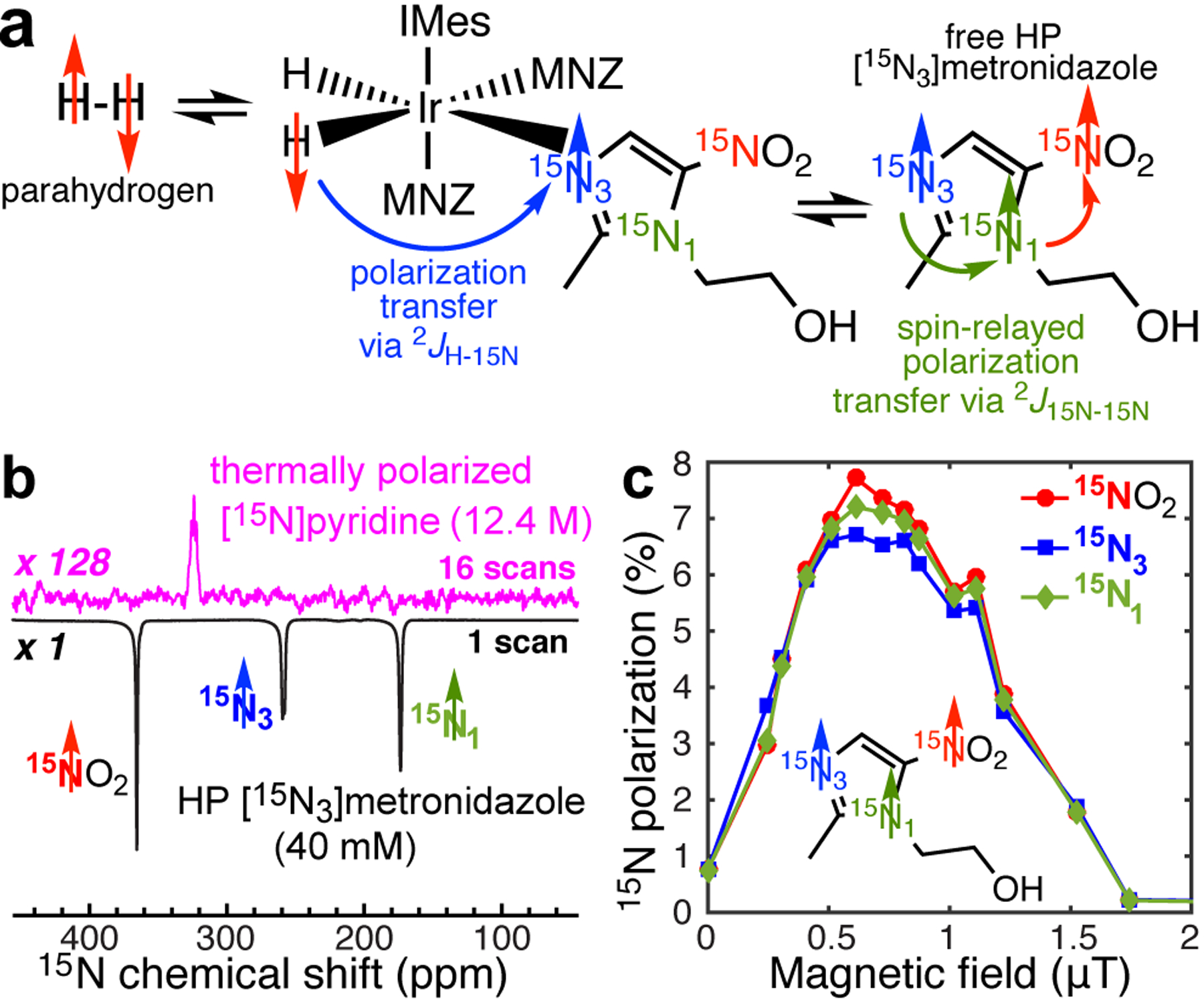
a) Simultaneous chemical exchange of p-H2 and [15N3]metronidazole (MNZ) on activated Ir-IMes catalyst enables spontaneous polarization transfer from p-H2-derived hydrides to 15N3 nucleus of [15N3]metronidazole followed by the spin-relayed spontaneous polarization transfer from 15N3 to 15N1 to 15NO2 sites; b) 15N NMR spectroscopy of [15N3]metronidazole hyperpolarized via SABRE-SHEATH and thermally polarized [15N]pyridine employed as a signal reference using 1.4 T bench-top NMR spectrometer; c) Magnetic field dependence of 15N signal of HP [15N3]metronidazole on the residual magnetic field inside the shield after magnetic shield degaussing to less than 20 nT residual magnetic field.
Results and Discussion
The described above circuit was successfully employed for degaussing three different kinds of magnetic shields (see Methods section) ranging in size from 3” (~7.6 cm) inner diameter (ID) and 9” (~22.9 cm) in height to 9” (~22.9 cm) ID and 27” (~0.69 m) in height using four different degaussing inductor coil configurations. These shields cover a wide range of scenarios for PHIP experiments and certainly provide sufficient volume for clinical-scale production of HP contrast agents.[48] In all cases, the mu-metal shields were degaussed to ≤ 20 nT residual magnetic field, even when the shields were strongly magnetized (>2 μT residual field) prior to degaussing. The degaussing procedure was reproducible – test-retest reproducibility with back-to-back degaussing events (N≥3) spaced by at least 20 mins with all three magnetic shields.
Note that the thermistors warm up during the degaussing process, and therefore require a sufficiently long (20 mins or more) cooling time. In cases, when such long waiting delays is not acceptable, we employed to alternatives: (i) construction of replica circuits and (ii) the use of air cooling to reduce the circuit recovery time to less than 5 min.[49] For example, we have employed one degaussing circuit with continuous air cooling to repeatedly degauss the 27-in. (~0.69-meter) shield after in-situ 13C NMR detection performed at B0 = 7.8 mT.[49] In this study, MFC was employed to produce 13C-hyperpolarized ethyl [1-13C]acetate via hydrogenative PHIP approach. We therefore anticipate the circuit recovery time not to be an issue in most envisioned applications.
The utility of the reported circuit to degauss the magnetic shield to less than 20 nT is demonstrated here for application in 15N SABRE-SHEATH studies. [15N3]metronidazole was successfully hyperpolarized using spin-relayed SABRE-SHEATH,[44] Figure 4a—Figure 4b shows 15N spectrum of HP [15N3]metronidazole recorded using 1.4 T bench-top NMR spectrometer. The 15N signal dependence on the applied magnetic field (by the solenoid coil placed inside the shield, Figure 3b), clearly shows a maximum at ~0.6 μT (Figure 4c), and 15N signal reduction to nearly zero, when no additional field was applied (i.e., the residual in-shield field was < 20 nT). This result is in sharp contrast with the previously published study performed without a precise magnetometer and the reported degaussing circuitry: as a result, the residual magnetic field was likely 0.2 μT resulting in two artifacts: (i) apparent maximum of 15N polarization at ~0.4 μT (vs. ~0.6 μT in Figure 4c) applied via solenoid magnetic field, and (ii) 15N signal phase shift (and thus the null point) at ~0.2 μT.[44] Such a residual magnetic field retained by the shield is therefore highly detrimental to SABRE-SHEATH experiments, because the actual “dialled” magnetic field of the in-shield solenoid (Figure 3) is added on top of the residual magnetic field of the shield, and may lead to systematic experimental biases. The described circuit in this Application paper mitigates these experimental challenges by conveniently fast and robust elimination of the residual in-shield field to below 20 nT.
Conclusion
In summary, we reported on robust and inexpensive ($73 cost of parts) circuitry for fast (~2 s) degaussing of mu-metal magnetic shields for their application with hyperpolarization techniques based on parahydrogen (PHIP and SABRE). Less than 20 nT residual field was reproducibly achieved with mu-metal shields of various sizes. The utility of degaussing was demonstrated by measuring the magnetic field profile in SABRE-SHEATH experiments with 15N hyperpolarization studies of [15N3]metronidazole. The simple circuitry presented here may be of practical use for those working and using PHIP and/or SABRE hyperpolarization techniques.
Supplementary Material
Acknowledgements
We thank the following for funding support: NSF CHE-1904780, NCI 1R21CA220137, NIBIB 1R01EB029829, NHLBI 1R21HL154032, DOD CDMRP W81XWH-15-1-0271 and W81XWH-20-10576.
Footnotes
Institute and/or researcher Twitter usernames: https://twitter.com/waynestatechem, https://twitter.com/e_chekmenev
References
- [1].Goodson BM, Whiting N, Coffey AM, Nikolaou P, Shi F, Gust BM, Gemeinhardt ME, Shchepin RV, Skinner JG, Birchall JR, Barlow MJ, Chekmenev EY, Emagres 2015, 4, 797–810. [Google Scholar]
- [2].Ardenkjaer-Larsen JH, Fridlund B, Gram A, Hansson G, Hansson L, Lerche MH, Servin R, Thaning M, Golman K, Proc. Natl. Acad. Sci. U. S. A 2003, 100, 10158–10163. [DOI] [PMC free article] [PubMed] [Google Scholar]
- [3].Goodson BM, J. Magn. Reson 2002, 155, 157–216. [DOI] [PubMed] [Google Scholar]
- [4].Ardenkjaer-Larsen JH, J. Magn. Reson 2016, 264, 3–12. [DOI] [PubMed] [Google Scholar]
- [5].Green RA, Adams RW, Duckett SB, Mewis RE, Williamson DC, Green GGR, Prog. Nucl. Mag. Res. Spectrosc 2012, 67, 1–48. [DOI] [PubMed] [Google Scholar]
- [6].Golman K, Axelsson O, Johannesson H, Mansson S, Olofsson C, Petersson JS, Magn. Reson. Med 2001, 46, 1–5. [DOI] [PubMed] [Google Scholar]
- [7].Golman K, in’t Zandt R, Thaning M, Proc. Natl. Acad. Sci. U. S. A 2006, 103, 11270–11275. [DOI] [PMC free article] [PubMed] [Google Scholar]
- [8].Day SE, Kettunen MI, Gallagher FA, Hu DE, Lerche M, Wolber J, Golman K, Ardenkjaer-Larsen JH, Brindle KM, Nat. Med 2007, 13, 1382–1387. [DOI] [PubMed] [Google Scholar]
- [9].Brindle KM, J. Am. Chem. Soc 2015, 137, 6418–6427. [DOI] [PubMed] [Google Scholar]
- [10].Bowers CR, Weitekamp DP, Phys. Rev. Lett 1986, 57, 2645–2648. [DOI] [PubMed] [Google Scholar]
- [11].Eisenschmid TC, Kirss RU, Deutsch PP, Hommeltoft SI, Eisenberg R, Bargon J, Lawler RG, Balch AL, J. Am. Chem. Soc 1987, 109, 8089–8091. [Google Scholar]
- [12].Hövener J-B, Pravdivtsev AN, Kidd B, Bowers CR, Glöggler S, Kovtunov KV, Plaumann M, Katz-Brull R, Buckenmaier K, Jerschow A, Reineri F, Theis T, Shchepin RV, Wagner S, Bhattacharya P, Zacharias NM, Chekmenev EY, Angew. Chem. Int. Ed 2018, 57, 11140–11162. [DOI] [PMC free article] [PubMed] [Google Scholar]
- [13].Rayner PJ, Duckett SB, Angew. Chem. Int. Ed 2018, 57, 6742–6753. [DOI] [PubMed] [Google Scholar]
- [14].Reineri F, Cavallari E, Carrera C, Aime S, Magn. Reson. Mater. Phy 2021, 34, 25–47. [DOI] [PMC free article] [PubMed] [Google Scholar]
- [15].Walker TG, J. Phys. Conf. Ser 2011, 294, 012001. [Google Scholar]
- [16].Mugler JP, Altes TA, J. Magn. Reson. Imaging 2013, 37, 313–331. [DOI] [PMC free article] [PubMed] [Google Scholar]
- [17].Kurhanewicz J, Vigneron DB, Ardenkjaer-Larsen JH, Bankson JA, Brindle K, Cunningham CH, Gallagher FA, Keshari KR, Kjaer A, Laustsen C, Mankoff DA, Merritt ME, Nelson SJ, Pauly JM, Lee P, Ronen S, Tyler DJ, Rajan SS, Spielman DM, Wald L, Zhang X, Malloy CR, Rizi R, Neoplasia 2019, 21, 1–16. [DOI] [PMC free article] [PubMed] [Google Scholar]
- [18].Driehuys B, Martinez-Jimenez S, Cleveland ZI, Metz GM, Beaver DM, Nouls JC, Kaushik SS, Firszt R, Willis C, Kelly KT, Wolber J, Kraft M, McAdams HP, Radiology 2012, 262, 279–289. [DOI] [PMC free article] [PubMed] [Google Scholar]
- [19].Johannesson H, Axelsson O, Karlsson M, C. R. Physique 2004, 5, 315–324. [Google Scholar]
- [20].Theis T, Truong ML, Coffey AM, Shchepin RV, Waddell KW, Shi F, Goodson BM, Warren WS, Chekmenev EY, J. Am. Chem. Soc 2015, 137, 1404–1407. [DOI] [PMC free article] [PubMed] [Google Scholar]
- [21].Barskiy DA, Shchepin RV, Tanner CPN, Colell JFP, Goodson BM, Theis T, Warren WS, Chekmenev EY, ChemPhysChem 2017, 18, 1493–1498. [DOI] [PubMed] [Google Scholar]
- [22].Pravdivtsev AN, Yurkovskaya AV, Vieth H-M, Ivanov KL, Kaptein R, ChemPhysChem 2013, 14, 3327–3331. [DOI] [PubMed] [Google Scholar]
- [23].Bales L, Kovtunov KV, Barskiy DA, Shchepin RV, Coffey AM, Kovtunova LM, Bukhtiyarov AV, Feldman MA, Bukhtiyarov VI, Chekmenev EY, Koptyug IV, Goodson BM, J. Phys. Chem. C 2017, 121, 15304–15309. [DOI] [PMC free article] [PubMed] [Google Scholar]
- [24].Eills J, Blanchard JW, Wu T, Bengs C, Hollenbach J, Budker D, Levitt MH, J. Chem. Phys 2019, 150, 174202. [DOI] [PubMed] [Google Scholar]
- [25].Cavallari E, Carrera C, Sorge M, Bonne G, Muchir A, Aime S, Reineri F, Sci. Rep 2018, 8, 8366. [DOI] [PMC free article] [PubMed] [Google Scholar]
- [26].Salnikov OG, Chukanov NV, Shchepin RV, Manzanera Esteve IV, Kovtunov KV, Koptyug IV, Chekmenev EY, J. Phys. Chem. C 2019, 123, 12827–12840. [DOI] [PMC free article] [PubMed] [Google Scholar]
- [27].Cavallari E, Carrera C, Aime S, Reineri F, J. Magn. Reson 2018, 289, 12–17. [DOI] [PubMed] [Google Scholar]
- [28].Muhammad SR, Greer RB, Ramirez SB, Goodson BM, Fout AR, ACS Catalysis 2021, 11, 2011–2020. [Google Scholar]
- [29].Adams RW, Aguilar JA, Atkinson KD, Cowley MJ, Elliott PIP, Duckett SB, Green GGR, Khazal IG, Lopez-Serrano J, Williamson DC, Science 2009, 323, 1708–1711. [DOI] [PubMed] [Google Scholar]
- [30].Adams RW, Duckett SB, Green RA, Williamson DC, Green GGR, J. Chem. Phys 2009, 131, 194505. [DOI] [PubMed] [Google Scholar]
- [31].Mewis RE, Magn. Reson. Chem 2015, 53, 789–800. [DOI] [PubMed] [Google Scholar]
- [32].Truong ML, Theis T, Coffey AM, Shchepin RV, Waddell KW, Shi F, Goodson BM, Warren WS, Chekmenev EY, J. Phys. Chem. C 2015, 119, 8786–8797. [DOI] [PMC free article] [PubMed] [Google Scholar]
- [33].Zhivonitko VV, Skovpin IV, Koptyug IV, Chem. Comm 2015, 51, 2506–2509. [DOI] [PubMed] [Google Scholar]
- [34].Mewis RE, Green RA, Cockett MCR, Cowley MJ, Duckett SB, Green GGR, John RO, Rayner PJ, Williamson DC, J. Phys. Chem. B 2015, 119, 1416–1424. [DOI] [PMC free article] [PubMed] [Google Scholar]
- [35].Norcott P, Burns MJ, Rayner PJ, Mewis RE, Duckett SB, Magn. Reson. Chem 2018, 56, 663–671. [DOI] [PMC free article] [PubMed] [Google Scholar]
- [36].Shchepin RV, Truong ML, Theis T, Coffey AM, Shi F, Waddell KW, Warren WS, Goodson BM, Chekmenev EY, J. Phys. Chem. Lett 2015, 6, 1961–1967. [DOI] [PMC free article] [PubMed] [Google Scholar]
- [37].Tanner CPN, Lindale JR, Eriksson SL, Zhou Z, Colell JFP, Theis T, Warren WS, J. Chem. Phys 2019, 151, 044201. [DOI] [PMC free article] [PubMed] [Google Scholar]
- [38].Barskiy DA, Shchepin RV, Coffey AM, Theis T, Warren WS, Goodson BM, Chekmenev EY, J. Am. Chem. Soc 2016, 138, 8080–8083. [DOI] [PMC free article] [PubMed] [Google Scholar]
- [39].Kidd BE, Gesiorski JL, Gemeinhardt ME, Shchepin RV, Kovtunov KV, Koptyug IV, Chekmenev EY, Goodson BM, J. Phys. Chem. C 2018, 122, 16848–16852. [DOI] [PMC free article] [PubMed] [Google Scholar]
- [40].Fekete M, Ahwal F, Duckett SB, J. Phys. Chem. B 2020, 124, 4573–4580. [DOI] [PMC free article] [PubMed] [Google Scholar]
- [41].Iali W, Roy SS, Tickner BJ, Ahwal F, Kennerley AJ, Duckett SB, Angew. Chem. Int. Ed 2019, 58, 10271–10275. [DOI] [PMC free article] [PubMed] [Google Scholar]
- [42].Tickner BJ, Semenova O, Iali W, Rayner PJ, Whitwood AC, Duckett SB, Catal. Sci. Tech 2020, 10, 1343–1355. [DOI] [PMC free article] [PubMed] [Google Scholar]
- [43].Salnikov OG, Chukanov NV, Svyatova A, Trofimov IA, Kabir MSH, Gelovani JG, Kovtunov KV, Koptyug IV, Chekmenev EY, Angew. Chem. Int. Ed 2021, 60, 2406–2413. [DOI] [PMC free article] [PubMed] [Google Scholar]
- [44].Birchall JR, Kabir MSH, Salnikov OG, Chukanov NV, Svyatova A, Kovtunov KV, Koptyug IV, Gelovani JG, Goodson BM, Pham W, Chekmenev EY, Chem. Comm 2020, 56, 9098–9101. [DOI] [PMC free article] [PubMed] [Google Scholar]
- [45].Shchepin RV, Birchall JR, Chukanov NV, Kovtunov KV, Koptyug IV, Theis T, Warren WS, Gelovani JG, Goodson BM, Shokouhi S, Rosen MS, Yen Y-F, Pham W, Chekmenev EY, Chem. Eur. J 2019, 25, 8829–8836. [DOI] [PMC free article] [PubMed] [Google Scholar]
- [46].Cowley MJ, Adams RW, Atkinson KD, Cockett MCR, Duckett SB, Green GGR, Lohman JAB, Kerssebaum R, Kilgour D, Mewis RE, J. Am. Chem. Soc 2011, 133, 6134–6137. [DOI] [PMC free article] [PubMed] [Google Scholar]
- [47].Nantogma S, Joalland B, Wilkens K, Chekmenev EY Anal. Chem 2021, 93, 3594–3601. [DOI] [PMC free article] [PubMed] [Google Scholar]
- [48].Kadlecek S, Vahdat V, Nakayama T, Ng D, Emami K, Rizi R, NMR Biomed. 2011, 24, 933–942. [DOI] [PubMed] [Google Scholar]
- [49].Joalland B, Schmidt A, Kabir MSH, Chukanov NV, Kovtunov KV, Koptyug IV, Hennig J, Hövener J-B, Chekmenev EY, Anal. Chem 2020, 92, 1340–1345. [DOI] [PMC free article] [PubMed] [Google Scholar]
Associated Data
This section collects any data citations, data availability statements, or supplementary materials included in this article.


