Abstract
Hydrochar, a hydrothermally carbonized product, has gained attention recently as an adsorbent, among its wide environmental applications. In this study, sludge from the paper recycling industry, having a lower pollution load, was used to produce hydrochar, followed by pre-activation and post-activation using KOH. Characterizations were performed for structural morphology (SEM and TEM), molecular functionalities (FTIR) and textural features (BET surface area). Furthermore, Response Surface Methodology (RSM) was used to optimize the adsorption parameters for the removal of orthophosphate with different hydrochars. This study aimed at a low-cost, waste-to-wealth, and negative emission technology for simultaneous solid waste management and orthophosphate removal in aqueous solution. It was predicted from the adsorption experiment that an orthophosphate dose of 100 mg L−1 at substrate pH 5.11 will result in the adsorption of 9.59 mg orthophosphate per g of post-activated hydrochar after 28.6 h, which was validated using further confirmation study.
Orthophosphate removal from aqueous solution by sludge-derived hydrochar was standardized and can be applied to prevent eutrophication.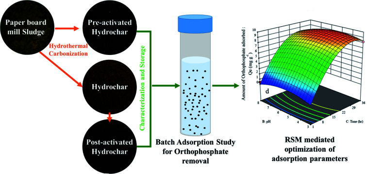
1. Introduction
Hydrochar, a low-cost adsorbent, processes the extensive removal of contaminants from wastewater. Hydrothermal carbonization of solid waste with higher moisture content serves as a superior factor among other thermochemical conversion processes. Multidisciplinary environmental application can be achieved through hydrothermal carbonization, especially for the preparation of adsorbent carbon materials. Besides the fuel applications, surface modification of carbon products widens the array of their environmental applications. The surface modification includes coarseness and development of cracks, thereby leading to the increase in overall surface area of the compound with net negative charge on the surface.1 This leads to the development of remediation potential for environmental contaminants from wastewater. Hydrochar is found to have more significant properties of an adsorbent material, due to the degradation of organic polymers resulting in the formation of carbon nanoparticles.
Generally, the activation of hydrochar can be carried out by physical and chemical activation methods. The use of KOH as a chemical activating agent yields carbon material with a higher surface area when using various biomass as precursors. The main advantage of using KOH as activating agent is that KOH molecules easily come in contact with the outer surface of the carbon material, which ensures the formation of activated carbon with micropores and mesopores.2 Moreover, KOH-activated carbon is superior over other carbon materials activated by ZnCl2, NaCl, HCl and MgCO3 due to its higher activation yield and higher total pore volume.3 KOH activation can be done by either direct chemical activation or char-impregnated chemical activation.2 However, activation in the current study was performed using direct chemical activation. During the activation process, the prevalence of higher temperature causes the breakdown of KOH into K2O, which is further reduced to form metallic K. The space between the carbonaceous layers is broadened by the metallic K vapors, thereby promoting an increased surface area of the carbon material.4 Additionally, the carbon dioxide generated during the simultaneous gasification helps with pore formation on the surface of the adsorbent material. An increase in activation temperature (800 °C) increases the surface area and porosity, but very high temperature causes a decrease in porosity of the adsorbents due to the combination of already-prevailing pores.5 The ratio of activating agent to char influences the surface area, porosity, and surface chemistry of the adsorbent material. Alkaline oxygen containing functional groups like carbonyl, carboxyl, phenolic, hydroxyl, and lactone groups are generated on the surface of the carbon material due to the usage of KOH as activating agent. Increasing the KOH-to-char ratio (1 : 0.5) shows a direct proportionality over the quantity of oxygen functional groups and surface area, thereby promoting enhanced adsorption of the prepared carbon material.6
The global production of paper was about 413 million tons in 2017,7 of which India accounts for 3.18% of the paper, paperboard and newsprint production per annum. These paper products are recycled after utilization through paperboard mill industries, thereby producing recycled paper and packaging materials. The Effluent Treatment Plants (ETP) of these industries generate solid waste known as paperboard mill sludge, which is managed by landfill formation and incineration. The paperboard mill sludge can be used for the production of hydrochar, with specific applications in energy generation and wastewater treatment.8
Phosphorous, an essential element required for functioning of biota, results in the degradation of fresh water bodies through the process of eutrophication when it prevails at higher concentrations in the form of orthophosphate. This potential risk is created by agricultural runoff and sewage. Orthophosphate concentrations above 0.02 mg L−1 promote algal bloom in water bodies, and its maximum permissible limit is 0.05 mg L−1.9 According to the Bureau of Indian Standards IS 10500, the permissible limit for discharge of phosphates in inland surface water is 5 mg L−1. Orthophosphate concentration in municipal wastewater ranges between 4 and 15 mg L−1, while in industrial effluents, it exceeds 25 mg L−1.10 Orthophosphate quantification is performed by different techniques, such as ion chromatography, high-performance liquid chromatography, atomic absorption spectroscopy, etc., among which UV-Vis spectrophotometry is preferred due to the simpler and cost-effective analysis, with the lowest limit of detection of 0.05 μg L−1.11 The removal of orthophosphate from polluted water bodies is achieved by physical, chemical and biological methods like electrodialysis, chemical precipitation, ion exchange, membrane technologies, reverse osmosis and biosorption, which involve high cost and energy consumption.12 However, the mechanism of adsorption is widely considered and applied due to its low cost and high efficiency.13 Some recent research works have illustrated the adsorption of orthophosphate by activated carbon from sewage sludge,14 coffee husk,15 bamboo,16 cocoa pod husk, rice husk, corn cob and palm kernel shell.17 However, there is no previous study on the utilization of paperboard mill sludge for hydrochar production and its application in orthophosphate removal. Moreover, every industry is facing the problem of disposing of large volumes of ETP sludge. Hydrochar production from sludge involves zero cost for raw material, and its disposal promotes a circular economy. Based on this scenario, the present study contemplates on the KOH activation of hydrochar and its utilization in the adsorptive removal of orthophosphates in synthetic wastewater. The orthophosphate adsorption parameters (orthophosphate dose, substrate pH, contact time and hydrochar type) were optimized using RSM.
2. Experimental methods
2.1. Hydrochar production
Paperboard mill sludge was collected from the effluent treatment plant at ITC Ltd., PSPD (Kovai unit), Coimbatore, India, and stored in sample containers at 4 °C. The sludge was homogenized, and about 60 g was taken in a 100 mL hydrothermal autoclave reactor in nitrogen atmosphere, after which the reactor was placed in a conventional hot-air oven.18 The temperature and time for hydrothermal carbonization was previously optimized as 200 °C and 10 h, respectively, using response surface methodology. After completing the predetermined process temperature and time, the reaction was quenched by the keeping the reactor in cold water. The hydrochar (HC) was dried, pulverized and stored for adsorption studies.19
2.1.1. Pre-activation with KOH
The paperboard mill sludge sample with a solid-to-water ratio of 1 : 9 was taken in a 100 mL hydrothermal autoclave reactor. Potassium hydroxide pellets were mixed with the sludge to obtain a KOH-to-sludge ratio of 2 : 1. The reactor was then kept in hot air at 200 °C for 10 h, after which the hydrothermally carbonized sludge was taken out, leached with 5 M HCl and washed with deionized water. The pre-activated hydrochar (PRHC) was dried, pulverized and stored for adsorption studies.20
2.1.2. Post-activation with KOH
Potassium hydroxide pellets were mixed with hydrochar to obtain a KOH-to-hydrochar ratio of 2 : 1 and kept in a tubular furnace at 600 °C for 1 h under nitrogen atmosphere with a heating rate of 5 °C per minute. The activated char samples were then taken and leached with 5 M HCl in order to remove the excess KOH, then washed with deionized water until they reached pH 7. The post-activated hydrochar (POHC) was dried, pulverized and used for adsorption studies.21
2.2. Characterization of hydrochar
The BET surface area of the hydrochar was measured using the Smartsorb 92/93 surface area analyzer. The point of zero charge was determined using the pH drift method. The functional groups prevailing in the samples were determined using FTIR (Model 8400S, Shimadzu, Japan) over the wavenumber range of 400–4000 cm−1.22 The zeta potential was measured using the particle size analyzer (Horiba Scientific Nanopartica SZ-100, Japan) by dispersing hydrochars in Milli-Q water with subsequent sonication.4 The surface, texture and morphological characteristics of the samples were interpreted by scanning electron microscope (SEM) (FEI – Quanta 250, Czech Republic) at a high voltage of 8 kV with 10 000× magnification. The internal morphology of the hydrochar samples was studied using transmission electron microscope (TEM) (FEI – Quanta 250, Czech Republic) operating at 120 kV.23
2.3. Batch adsorption studies
Orthophosphate adsorption was investigated by varying the orthophosphate dose, pH, contact time and hydrochar type (Table 1) at a fixed adsorbent dose of 4 g L−1. Batch adsorption studies were performed at room temperature (25 °C) in 50 mL centrifuge tubes rotated in an end-to-end shaker at 250 rpm, each containing 25 mL of orthophosphate solution of known variations. The pH of the solutions was adjusted using 1% NaOH and 1% HCl, respectively. The quantification of orthophosphate was done using UV-Vis spectrophotometry (Shimadzu UV-1800) at 660 nm by adopting the ammonium molybdate and ascorbic acid method.24
Variables for batch adsorption studies.
| Factor no. | Factor name | Levels of factor | |||||
|---|---|---|---|---|---|---|---|
| I | II | III | IV | V | VI | ||
| 1 | Orthophosphate dose (mg L−1) | 25 | 50 | 75 | 100 | — | — |
| 2 | pH | 3 | 5 | 8 | — | — | — |
| 3 | Contact time (h) | 1 | 3 | 6 | 12 | 24 | 36 |
| 4 | Hydrochar type | HC | PRHC | POHC | — | — | — |
2.3.1. Optimization of orthophosphate adsorption
The integrated optimal (I-optimal) design of Response Surface Methodology (RSM) was employed for the optimization of orthophosphate adsorption by hydrochars. The I-optimal design was chosen to match a quadratic polynomial model with the least number of experiments that facilitated the investigation of interaction between the adsorption parameters and recognized the main factor for response optimization. The adsorption parameters for optimization and their respective coded levels are listed in the Table 1. The amount of orthophosphate adsorbed was set as the target parameter (response) for optimization. Forty-five experimental runs with random combinations of adsorption parameters were suggested, which were performed, and the respective amount of orthophosphate adsorption was calculated (ESI Table 1†). The response data from the experimental run were analyzed using Design-Expert software version 11 from Stat-Ease Inc. 2000.
3. Results and discussion
3.1. Characterization of hydrochars
3.1.1. Surface charge and surface area analysis
The zeta potential of HC was −17.1 mV, while it became further negative for PRHC (−20.6 mV) and POHC (−38 mV), respectively. The small zeta potential value of HC and PRHC showed incipient unstable behavior. However, the more negative value of POHC indicated a higher degree of stability. Generally, zeta potential values greater than +30 mV or less than −30 mV indicate high degrees of stability.25 The surface area of HC, PRHC and POHC were 16.32 m2 g−1, 76.6 m2 g−1 and 86.16 m2 g−1, respectively. The lower surface area of the activated hydrochars was due to higher activation temperature (>800 °C) and longer retention time (>0.5 h), which caused the intercalation of potassium ions into the carbon matrix, accelerating carbon liberation and the collapse of meso and micro pores to form macropores.2 Moreover, sludge-derived carbon exhibited lower surface area due to a higher mineral content than other activated carbon sources.26 The surface charge of HC, PRHC and POHC were 7.7, 7.3 and 9.1, respectively.
3.1.2. Surface functionalities
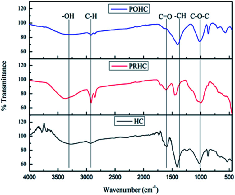
The FTIR spectrum of HC (Fig. 1) portrayed a broad variable OH stretching band around 3200–3600 cm−1 due to the presence of cellulose and a rounded tip at 3260 cm−1 due to phenolic OH groups. The weak intensity of these peaks is an indication that dehydration and decarboxylation reactions occurred during the process.27 The band between 2800 cm−1 and 3000 cm−1 represents the vibration of aliphatic methyl groups with a centroid at 2920 cm−1, which indicated the presence of amino acids by asymmetric C–H stretching. The C O stretching band at 1592 cm−1 indicates the proteins made of amide groups due to the characteristic C–N stretching vibration of amides.28 The presence of –CH aliphatic compounds like –CH2 and –CH3 was portrayed by a sharp peak at 1412 cm−1. The asymmetric stretching of C–O–C at 1026 cm−1 corresponds to the dehydration reaction of alcohol.
Fig. 1. FTIR spectra of hydrochars.
Similar FTIR spectra were obtained for PRHC and POHC, wherein activation has resulted in the increased intensity of O–H, C–H, aromatic C C, aromatic C O and C–H stretching, eventually resulting in broad band shift.29 However, the band at 1404 cm−1 showed reduced intensity due to partial hydrolytic degradation of cellulose after activation.30 The reduction of the peak at 1026 cm−1 corresponding to C–O–C vibrations was due to OH deprotonation at the surface of KOH-activated hydrochars.14 The oxygenated functional groups, especially the carboxylic groups, have shown increased intensification after the activation process. The presence of phenolic, carboxylic and amino groups on the char enhanced its affinity towards orthophosphate.31 This is attributed to the negative zeta potentials of PRHC and POHC, respectively, thereby improving their adsorption capacities.32
3.1.3. Structural morphologies
The scanning electron microscopy of activated hydrochars showed the formation of microspheres due to intensive carbonization (Fig. 2). The presence of KOH during activation boosted the formation of spherical and porous carbon particles that enhanced the adsorptive potential of hydrochars.33 The TEM micrographs of hydrochar samples portrayed the formation of spherical carbon nanoparticles (Fig. 3). The diameter of carbon spheres formed after pre-activation ranged between 20.6 nm to 37.2 nm, while the diameter of carbon spheres formed after post-activation ranged between 20.4 nm to 66.6 nm. The presence of KOH enhanced the removal of impurities from pores and cracks, thus forming activated hydrochar with a cleaner surface. The formation of nanostructure with a porous surface could be attributed to the morphological changes observed on the surface of activated hydrochars. Similar results were found during the hydrothermal carbonization of wheat straw, corn stalk and saw dust, whose KOH activation resulted in the production of much cleaner and porous carbon material that promoted the adsorption of heavy metals from wastewater.32
Fig. 2. SEM micrographs of hydrochars. (A) HC, (B) PRHC and (C) POHC.
Fig. 3. TEM micrographs of hydrochars. (A) HC, (B) PRHC and (C) POHC.
3.2. Orthophosphate adsorption
3.2.1. Effect of pH
The pH of the solution serves as an important factor for orthophosphate adsorption due to the availability of orthophosphate and the surface charge of the adsorbent at different pH levels. The orthophosphate adsorption capacity attained maximum value when the pH was increased from 3 to 5. The hydrochar surface protonated and acquired positive charge at the lower pH of the solution than their pHzpc, promoting the favorable adsorption of orthophosphate. Moreover, the lower pH favors the higher availability of orthophosphates compared to higher pH conditions, and the adsorption energy of orthophosphates is much lower than other phosphate species.16
3.2.2. Effect of contact time
The rate of orthophosphate adsorption by HC, PRHC and POHC gradually increased to 3.90 mg g−1, 4.60 mg g−1 and 5.17 mg g−1 at 24 h, respectively. However, the rate of adsorption showed a drastic decrease after 24 h. The point at which adsorption rate starts decreasing is indicated as equilibrium time for orthophosphate adsorption. The higher rate of adsorption at initial time depicted the presence of readily available adsorption sites, and eventually, the rate decreases gradually over time due to saturation.
3.2.3. Effect of initial concentration
The rate of adsorption of orthophosphate on the HC, PRHC and POHC increased with an increase in initial concentration. When the equilibrium concentration (Ce) increases, the adsorption capacity increases for all the adsorbents. When the initial concentration was increased from 25 mg L−1 to 100 mg L−1 at pH 5, the rate of adsorption capacity increased from 3.18 to 7.19 mg g−1, 4.6 to 10.98 mg g−1 and 5.17 to 12.85 mg g−1 for HC, PRHC and POHC, respectively.
3.3. Statistical analysis of orthophosphate adsorption
The utilization of Design-Expert software led to the optimization of adsorption parameters (orthophosphate dose, substrate pH, contact time and hydrochar type) in order to achieve maximum adsorption of orthophosphate. An analysis of variance (ANOVA) was carried out to analyze the experimental results, as shown in Table 2. The probability (p-value) and Fischer test value (F-value) were used to compute the regression model for orthophosphate adsorption. The model of the response was found to be significant due to the higher F-value and lower p-value.34
ANOVA for orthophosphate removal by different hydrocharsa.
| SS | df | MSS | F-value | p-value | S/NS | |
|---|---|---|---|---|---|---|
| Model | 391.8 | 17 | 23.05 | 31.75 | <0.0001 | S |
| A-Orthophosphate dose (mg L−1) | 29.3 | 1 | 29.39 | 40.48 | <0.0001 | S |
| B-pH | 2.04 | 1 | 2.04 | 2.81 | 0.1054 | NS |
| C-Time (h) | 200.7 | 1 | 200.78 | 276.5 | <0.0001 | S |
| D-Carbon material | 14.8 | 2 | 7.44 | 10.25 | 0.0005 | S |
| AB | 1.60 | 1 | 1.60 | 2.20 | 0.1493 | NS |
| AC | 18.15 | 1 | 18.15 | 25.01 | <0.0001 | S |
| AD | 4.13 | 2 | 2.07 | 2.85 | 0.0756 | NS |
| BC | 0.28 | 1 | 0.283 | 0.391 | 0.5370 | NS |
| BD | 1.72 | 2 | 0.860 | 1.19 | 0.3210 | NS |
| CD | 3.44 | 2 | 1.72 | 2.37 | 0.1124 | NS |
| A 2 | 5.09 | 1 | 5.09 | 7.02 | 0.0133 | S |
| B 2 | 8.54 | 1 | 8.54 | 11.76 | 0.0020 | S |
| C 2 | 74.75 | 1 | 74.75 | 102.9 | <0.0001 | S |
| Residual | 19.6 | 27 | 0.725 | |||
| Lack of fit | 19.4 | 18s | 1.08 | 48.79 | <0.0001 | S |
| Pure error | 0.198 | 9 | 0.0221 | |||
| Cor total | 411.4 | 44 | ||||
| Std. dev. | 0.8520 | R 2 | 0.9524 | |||
| Mean | 3.81 | Adjusted R2 | 0.9224 | |||
| C.V.% | 22.34 | Predicted R2 | 0.8407 | |||
S – significant, NS – non-significant.
The best fitted model for orthophosphate removal was a quadratic model, with R2 value of 0.9524, and the corresponding equations for HC (1), PRHC (2) and POHC (3) were derived.
| Y = 0.08A + 1.91B + 0.45C − 0.003AB + 0.02AC − 0.003BC − 0.0005A2 − 0.16B2 − 0.01C2 − 6.98 | 1 |
| Y = 0.1A + 1.76B + 0.48C − 0.003AB + 0.001AC − 0.002BC − 0.0006A2 − 0.16B2 − 0.01C2 − 7.36 | 2 |
| Y = 0.1A + 2.01B + 0.49C − 0.003AB + 0.001AC − 0.002BC − 0.0006A2 − 0.16B2 − 0.01C2 − 8.25 | 3 |
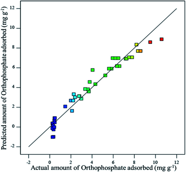
where Y denotes the amount of orthophosphate adsorbed (mg g−1), A denotes the orthophosphate dose (mg L−1), B denotes the substrate pH and C depicts the contact time (h). The effect of specific factor and the interaction among the factors were pointed out by coefficients with one and two factors, respectively. The positive sign denotes a synergistic relation, while the negative sign denotes an antagonistic relation. The experimental values and the predicted values for orthophosphate adsorption were found to have good correlation, which confirmed the robustness of the developed model (Fig. 4).
Fig. 4. Relationship between actual and predicted values of orthophosphate removal.
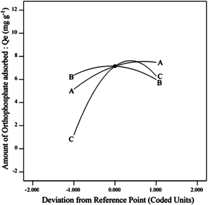
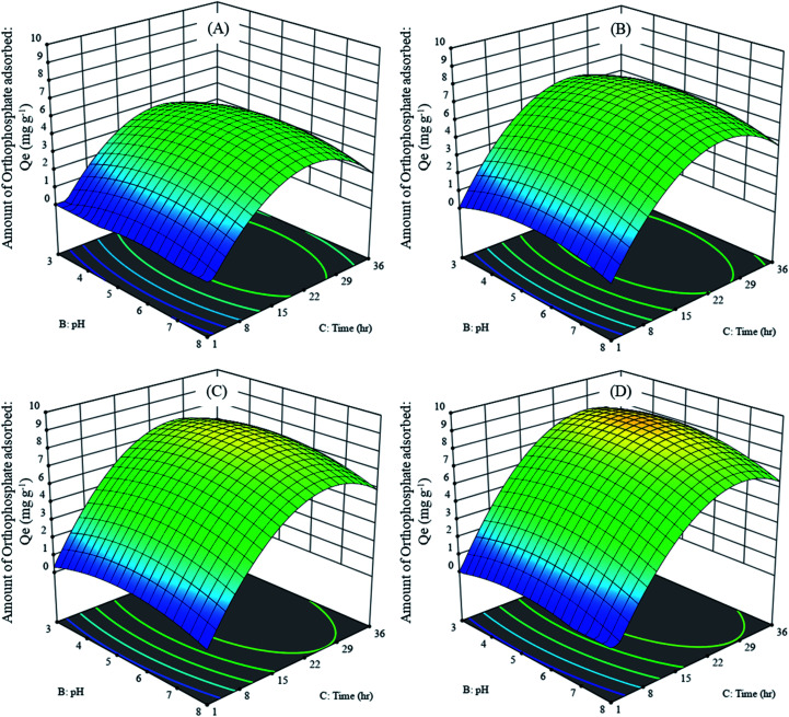
The effect of adsorption parameters on orthophosphate removal was determined using a perturbation plot (Fig. 5) and three-dimensional response surface plots (Fig. 6). The perturbation plot helps in evaluating the effect of all adsorption parameters at a specific point and monitoring its behavior to check the changes undergone by every response to the respective change in adsorption parameter.34 The extent of sensitivity of orthophosphate removal to the adsorption parameters is highlighted by a steep slope or a curvature. The yellow region in the three-dimensional plots denotes higher orthophosphate adsorption, while the blue region denotes lower adsorption. The amount of adsorbed orthophosphate increased with the increase in contact time, up to 24 h, after which it started to decline. In addition, the amount of orthophosphate adsorption varied with the substrate pH, orthophosphate dose and the hydrochar type (ESI Fig. S1–S3†). The statistical optimization has resulted in the projection of some solutions (optimized adsorption parameters), among which the adsorption experiment involving post-activated hydrochar with orthophosphate dose of 100 mg L−1 at a substrate pH 5.11 was concluded to be the optimized adsorption parameter due to its higher predicted probability of 90.5%. This may result in the adsorption of 9.59 mg orthophosphate per g of post-activated hydrochar after 28.6 h, which was validated using further confirmation study.
Fig. 5. Effect of perturbation plot on orthophosphate removal.
Fig. 6. Three-dimensional response surface curve of adsorption parameters on average orthophosphate adsorbed by different hydrochars at an initial orthophosphate dose of (A) 25 mg L−1, (B) 50 mg L−1, (C) 75 mg L−1 and (D) 100 mg L−1.
3.4. Adsorption isotherm and kinetics
The adsorption of orthophosphate on hydrochar was examined using kinetic and isotherm parameters at pH 3, pH 5 and pH 8, respectively. The kinetic models employed for adsorption are pseudo-first order, pseudo-second order, Elovich and intraparticle models (ESI Tables 2 and 3†). The coefficient of determination (R2) indicated the best suited model for studying the mechanism of adsorption.
The kinetic parameters at the initial orthophosphate concentration of 25 mg L−1 for different pH levels are depicted in Table 3. Pseudo second-order kinetics emerged as the best fitting model (R2) for the orthophosphate adsorption by HC (0.7377), PRHC (0.7126) and POHC (0.7335) at pH 5, with maximum adsorption capacity of 2.39, 2.77 and 3.21 mg g−1, respectively. The R2 values of pseudo-first order were found lower for HC (0.7122), PRHC (0.6374) and POHC (0.6256). The intraparticle diffusion model for hydrochars also fitted well, indicating it as the rate-limiting mechanism of adsorption.
Kinetic parameters for orthophosphate adsorption by hydrochars.
| Kinetic parameters | pH 3 | pH 5 | pH 8 | |||||||
|---|---|---|---|---|---|---|---|---|---|---|
| HC | PRHC | POHC | HC | PRHC | POHC | HC | PRHC | POHC | ||
| Pseudo-first order | R 2 | 0.7637 | 0.6899 | 0.5476 | 0.7122 | 0.6374 | 0.6256 | 0.8035 | 0.7291 | 0.6551 |
| K 1 (min−1) | 0.0004 | 0.0004 | 0.0004 | 0.0004 | 0.0004 | 0.0006 | 0.0004 | 0.0004 | 0.0004 | |
| Pseudo-second order | R 2 | 0.7489 | 0.7157 | 0.7049 | 0.7377 | 0.7126 | 0.7335 | 0.7506 | 0.7247 | 0.6961 |
| K 2 (g mg−1 min−1) | 0.0610 | 0.0999 | 0.1031 | 0.0716 | 0.1137 | 0.1750 | 0.0480 | 0.0762 | 0.0970 | |
| Elovich | R 2 | 0.7612 | 0.7488 | 0.7038 | 0.7456 | 0.7373 | 0.7038 | 0.7634 | 0.7591 | 0.7351 |
| α (mg g−1 min−1) | 55.6626 | 68.9872 | 68.8631 | 59.4897 | 71.4767 | 80.7558 | 51.6533 | 62.1344 | 70.0282 | |
| β (mg g−1) | 1.2116 | 1.0164 | 0.9705 | 1.1381 | 0.9649 | 0.8445 | 1.3152 | 1.1163 | 1.0134 | |
| Intraparticle | R 2 | 0.7443 | 0.7372 | 0.6718 | 0.7295 | 0.7202 | 0.7365 | 0.7497 | 0.7422 | 0.7206 |
| K i (mg g−1 h0.5) | 0.288 | 0.3892 | 0.3222 | 0.3106 | 0.3833 | 0.4146 | 0.2743 | 0.3373 | 0.3973 | |
The parameters for Langmuir, Freundlich and Temkin isotherm models are exhibited in Table 4. Langmuir model showed maximum R2 values for HC (0.996), PRHC (0.987) and POHC (0.975) at pH 5. The theoretical maximum orthophosphate adsorption capacities at pH 5 for HC, PRHC and POHC were 8.23 mg g−1, 13.4 mg g−1 and 15.1 mg g−1, respectively (ESI Fig. S4 and S5†). The RL value ranges between 0 and 1 irrespective of pH, indicating the favorable adsorption process.
Isotherm parameters for orthophosphate adsorption by hydrochars.
| Isotherm parameters | pH 3 | pH 5 | pH 8 | |||||||
|---|---|---|---|---|---|---|---|---|---|---|
| HC | PRHC | POHC | HC | PRHC | POHC | HC | PRHC | POHC | ||
| Freundlich | R 2 | 0.580 | 0.410 | 0.665 | 0.911 | 0.997 | 0.997 | 0.844 | 0.993 | 0.996 |
| K f (mg1−1/n L1/n g−1) | 1.351 | 1.343 | 1.418 | 1.365 | 1.404 | 1.607 | 1.251 | 1.211 | 1.298 | |
| n | 3.516 | 2.558 | 2.396 | 3.185 | 2.496 | 2.706 | 3.257 | 2.378 | 2.257 | |
| Langmuir | R 2 | 0.984 | 0.997 | 0.986 | 0.996 | 0.987 | 0.975 | 0.985 | 0.994 | 0.996 |
| X m (mg g−1) | 6.845 | 11.669 | 14.641 | 8.230 | 13.405 | 15.106 | 6.557 | 11.148 | 13.793 | |
| K l (L g−1) | 0.140 | 0.105 | 0.070 | 0.133 | 0.081 | 0.049 | 0.201 | 0.150 | 0.093 | |
| R l | 0.510 | 0.448 | 0.493 | 0.478 | 0.479 | 0.576 | 0.431 | 0.374 | 0.438 | |
| Temkin | R 2 | 0.815 | 0.994 | 0.984 | 0.933 | 0.988 | 0.967 | 0.851 | 0.998 | 0.996 |
| B (kJ mol−1) | 1.798 | 0.971 | 0.785 | 1.457 | 0.860 | 0.816 | 1.801 | 0.991 | 0.801 | |
| K t (L g−1) | 1.685 | 1.458 | 1.459 | 1.225 | 1.405 | 1.139 | 1.179 | 2.004 | 1.894 | |
3.5. Mechanism of orthophosphate adsorption
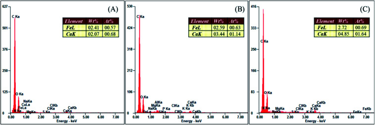
The KOH post-activation of sewage sludge-derived hydrochar showed a maximum orthophosphate adsorption of 14.3 mg g−1 when the initial concentration of orthophosphate was 150 mg L−1. The mechanism involved in the adsorption of orthophosphate by hydrochar includes ion exchange, ligand exchange, hydrogen bonding and diffusion reactions.35 Moreover, KOH activation promotes the dissolution of calcium and iron. The embedding of these elements in the skeletal part of the hydrochar has resulted in the enhanced adsorption of orthophosphate by forming respective orthophosphate precipitates.14 The EDAX of hydrochars (Fig. 7) confirmed the presence of calcium and iron for the enhanced adsorption of orthophosphates. However, lower quantities of calcium and iron in the hydrochars were responsible for lower adsorption capacities as compared with other activated hydrochars. The hydroxyl groups present in the activated hydrochar were responsible for the removal of orthophosphate, as the activated hydrochar possessed 1.7 times OH richness than raw hydrochar, and adsorption takes place through an ion exchange mechanism.14 Similarly, coffee husk-derived ZnCl2 activated hydrochar exhibited a higher orthophosphate adsorption of 59.38 mg g−1 to 63.87 mg g−1 at a pH range of 5 to 9, with an initial orthophosphate concentration of 50 mg L−1.15
Fig. 7. EDAX analyses of hydrochars. (A) HC, (B) PRHC and (C) POHC.
3.6. Safe disposal of orthophosphate-adsorbed hydrochar
The disposal of orthophosphate-adsorbed hydrochar does not create any environmental problems because it can be used for soil amendment and slowly release phosphate nutrient fertilizer. Soil leaching experiments of phosphate-laden rice husk biochar exhibited increased phosphorus availability in low P index soils.36 Similarly, phosphate-laden cotton stalk biochar enhanced black gram yield and served as microbial population multiplier in soil microbial fuel cells.37 This suggests the sustainable recovery of residual phosphates from agricultural runoff and their reutilization as nutrient for soil microbes and plant growth, thus promoting the circular economy of phosphate management.
4. Conclusion
KOH activation of hydrochar-produced carbon microspheres with higher proportion of oxygenated functional groups facilitated the maximum removal of orthophosphate from aqueous solution. The adsorption by post-activated hydrochar was optimized to be 9.59 mg g−1 at the orthophosphate dose of 100 mg L−1 and at substrate pH 5.11 after 28.6 h, which was validated by confirmation study. Hence, the eutrophication of orthophosphate-enriched water bodies can be controlled. This concurrent novel approach directs an efficient wet sludge management and low-cost water treatment system. Further scaled-up studies can be performed for the restoration of water bodies polluted with orthophosphate.
Author contributions
Oumabady Sadish: methodology, formal analysis, investigation, writing – original draft; Selvaraj Paul Sebastian: conceptualization, validation, writing – review and editing, project administration; Sara Parwin Banu Kamaludeen: supervision, validation, writing – review and editing; Ettiyagounder Parameswari: resources, supervision; Kathirvel Suganya: supervision, resources; R. Sangeetha Piriya: formal analysis, investigation.
Conflicts of interest
There are no conflicts to declare.
Supplementary Material
Acknowledgments
This study was financially supported by ITC Ltd., (PSPD unit), Coimbatore, Tamil Nadu, India. The laboratory experiments and characterization were carried out in the Department of Environmental Sciences, Tamil Nadu Agricultural University, Coimbatore, Tamil Nadu, India.
Electronic supplementary information (ESI) available. See DOI: 10.1039/d0ra10943f
References
- Fang J. Gao B. Chen J. Zimmerman A. R. Chem. Eng. J. 2015;267:253–259. doi: 10.1016/j.cej.2015.01.026. [DOI] [Google Scholar]
- Hui T. S. Zaini M. A. A. Carbon Lett. 2015;16:275–280. doi: 10.5714/CL.2015.16.4.275. [DOI] [Google Scholar]
- Grycova B. Pryszcz A. Matejova L. Lestinsky P. Chem. Eng. Trans. 2018;70:1897–1902. [Google Scholar]
- Hwang H. R. Choi W. J. Kim T. J. Kim J. S. Oh K. J. J. Anal. Appl. Pyrolysis. 2008;83:220–226. doi: 10.1016/j.jaap.2008.09.011. [DOI] [Google Scholar]
- Hunsom M. Autthanit C. Chem. Eng. J. 2013;229:334–343. doi: 10.1016/j.cej.2013.05.120. [DOI] [Google Scholar]
- Nunthaprechachan T. Pengpanich S. Hunsom M. Chem. Eng. J. 2013;228:263–271. doi: 10.1016/j.cej.2013.04.067. [DOI] [Google Scholar]
- FAOSTAT, http://www.fao.org/faostat/en/#data, (accessed 15 July 2019)
- Oumabady S. Paul Sebastian P. S. Kamaludeen S. P. B. Ramasamy M. Kalaiselvi P. Parameswari E. Sci. Rep. 2020;10:773. doi: 10.1038/s41598-019-57163-7. [DOI] [PMC free article] [PubMed] [Google Scholar]
- USEPA, Ecol. Restor. A Tool To Manag. Stream Qual., 1995, vol. 1–2 [Google Scholar]
- Mekonnen D. T. Alemayehu E. Lennartz B. Water. 2020;12:1381. doi: 10.3390/w12051381. [DOI] [Google Scholar]
- Ganesh S. Khan F. Ahmed M. K. Velavendan P. Pandey N. K. Kamachi Mudali U. Water Sci. Technol. 2012;66:2653–2658. doi: 10.2166/wst.2012.468. [DOI] [PubMed] [Google Scholar]
- Bunce J. T. Ndam E. Ofiteru I. D. Moore A. Graham D. W. Front. Environ. Sci. 2018;6:8. doi: 10.3389/fenvs.2018.00008. [DOI] [Google Scholar]
- Yang Q. Wang X. Luo W. Sun J. Xu Q. Chen F. Zhao J. Wang S. Yao F. Wang D. Li X. Zeng G. Bioresour. Technol. 2018;247:537–544. doi: 10.1016/j.biortech.2017.09.136. [DOI] [PubMed] [Google Scholar]
- Spataru A. Jain R. Chung J. W. Gerner G. Krebs R. Lens P. N. L. RSC Adv. 2016;6:101827–101834. doi: 10.1039/C6RA22327C. [DOI] [Google Scholar]
- Cruz J. F. Valdiviezo G. Carrión L. Rimaycuna J. Ainassaari K. Gómez M. M. Solis J. L. Keiski R. L. Cruz G. J. F. J. Phys.: Conf. Ser. 2019;1173:012007. doi: 10.1088/1742-6596/1173/1/012007. [DOI] [Google Scholar]
- Jiang D. Chu B. Amano Y. Machida M. Colloids Surf., A. 2018;558:429–437. doi: 10.1016/j.colsurfa.2018.09.016. [DOI] [Google Scholar]
- Eduah J. O. Nartey E. K. Abekoe M. K. Henriksen S. W. Andersen M. N. Environ. Technol. Innovation. 2020;17:100572. doi: 10.1016/j.eti.2019.100572. [DOI] [Google Scholar]
- Lin Y. Ma X. Peng X. Hu S. Yu Z. Fang S. Appl. Therm. Eng. 2015;91:574–582. doi: 10.1016/j.applthermaleng.2015.08.064. [DOI] [Google Scholar]
- Nakason K. Panyapinyopol B. Kanokkantapong V. Viriya-empikul N. Kraithong W. Pavasant P. J. Energy Inst. 2018;91:184–193. doi: 10.1016/j.joei.2017.01.002. [DOI] [Google Scholar]
- Jain A. Balasubramanian R. Srinivasan M. P. Microporous Mesoporous Mater. 2015;203:178–185. doi: 10.1016/j.micromeso.2014.10.036. [DOI] [Google Scholar]
- Puccini M. Stefanelli E. Hiltz M. Seggiani M. Vitolo S. Chem. Eng. Trans. 2017;57:169–174. [Google Scholar]
- Trakal L. Bingöl D. Pohořelý M. Hruška M. Komárek M. Bioresour. Technol. 2014;171:442–451. doi: 10.1016/j.biortech.2014.08.108. [DOI] [PubMed] [Google Scholar]
- Kliewer C. E., in Zeolite Characterization and Catalysis, Springer, 2009, pp. 169–196 [Google Scholar]
- Li S. Liu D. Metall. Anal. 2006;26:82–83. [Google Scholar]
- Kumar A. and Dixit C. K., in Advances in Nanomedicine for the Delivery of Therapeutic Nucleic Acids, Elsevier Inc., 2017, pp. 44–58 [Google Scholar]
- Kong L. Hu X. Xie Z. Ren X. Long J. Su M. Diao Z. Chen D. Shih K. Hou L. Sci. Rep. 2018;8:13421. doi: 10.1038/s41598-018-31750-6. [DOI] [PMC free article] [PubMed] [Google Scholar]
- Elaigwu S. E. Greenway G. M. Int. J. Ind. Chem. 2016;7:449–456. doi: 10.1007/s40090-016-0081-0. [DOI] [Google Scholar]
- Jaria G. Calisto V. Silva C. P. Gil M. V. Otero M. Esteves V. I. Sci. Total Environ. 2019;653:393–400. doi: 10.1016/j.scitotenv.2018.10.346. [DOI] [PubMed] [Google Scholar]
- Mihajlović M. Petrović J. Kragović M. Stojanović M. Milojković J. Lopičić Z. Koprivica M. RAD Assoc. J. 2017;2:65–67. [Google Scholar]
- Regmi P. Garcia Moscoso J. L. Kumar S. Cao X. Mao J. Schafran G. J. Environ. Manage. 2012;109:61–69. doi: 10.1016/j.jenvman.2012.04.047. [DOI] [PubMed] [Google Scholar]
- Li H. Dong X. da Silva E. B. de Oliveira L. M. Chen Y. Ma L. Q. Chemosphere. 2017;178:466–478. doi: 10.1016/j.chemosphere.2017.03.072. [DOI] [PubMed] [Google Scholar]
- Sun K. Tang J. Gong Y. Zhang H. Environ. Sci. Pollut. Res. 2015;22:16640–16651. doi: 10.1007/s11356-015-4849-0. [DOI] [PubMed] [Google Scholar]
- Zhang X. Li Y. Wang M. Han L. Liu X. Energy Fuels. 2020;34:587–598. doi: 10.1021/acs.energyfuels.9b03754. [DOI] [Google Scholar]
- Nizamuddin S. Mubarak N. M. Tiripathi M. Jayakumar N. S. Sahu J. N. Ganesan P. Fuel. 2016;163:88–97. doi: 10.1016/j.fuel.2015.08.057. [DOI] [Google Scholar]
- Loganathan P. Vigneswaran S. Kandasamy J. Bolan N. S. Crit. Rev. Environ. Sci. Technol. 2014;44:847–907. doi: 10.1080/10643389.2012.741311. [DOI] [Google Scholar]
- Pratiwi E. P. A. Hillary A. K. Fukuda T. Shinogi Y. Geoderma. 2016;277:61–68. doi: 10.1016/j.geoderma.2016.05.006. [DOI] [Google Scholar]
- Krishna Veni D. Kannan P. Jebakumar Immanuel Edison T. N. Senthilkumar A. J. Waste Manage. 2017;68:752–759. doi: 10.1016/j.wasman.2017.06.032. [DOI] [PubMed] [Google Scholar]
Associated Data
This section collects any data citations, data availability statements, or supplementary materials included in this article.


