Abstract
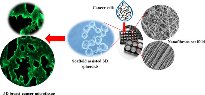
Three-dimensional (3D) tissue culture has attracted a great deal of attention as a result of the need to replace the conventional two-dimensional cell cultures with more meaningful methods, especially for understanding the sophisticated nature of native tumor microenvironments. However, most techniques for 3D tissue culture are laborious, expensive, and limited to spheroid formation. In this study, a low-cost and highly effective nanofibrous scaffold is presented for spontaneous formation of reproducible 3D breast cancer microtissues. Experimentally, aligned and non-aligned chitosan/poly(ethylene oxide) nanofibrous scaffolds were prepared at one of two chitosan concentrations (2 and 4 wt %) and various electrospinning parameters. The resulting fabricated scaffolds (C2P1 and C4P1) were structurally and morphologically characterized, as well as analyzed in silico. The obtained data suggest that the fiber diameter, surface roughness, and scaffold wettability are tunable and can be influenced based on the chitosan concentration, electrospinning conditions, and alignment mode. To test the usefulness of the fabricated scaffolds for 3D cell culture, a breast cancer cell line (MCF-7) was cultured on their surfaces and evaluated morphologically and biochemically. The obtained data showed a higher proliferation rate for cells grown on scaffolds compared to cells grown on two-dimensional adherent plates (tissue culture plate). The MTT assay revealed that the rate of cell proliferation on nanofibrous scaffolds is statistically significantly higher compared to tissue culture plate (P ≤ 0.001) after 14 days of culture. The formation of spheroids within the first few days of culture shows that the scaffolds effectively support 3D tissue culture from the outset of the experiment. Furthermore, 3D breast cancer tissues were spontaneously formed within 10 days of culture on aligned and non-aligned nanofibrous scaffolds, which suggests that the scaffolds imitate the in vivo extracellular matrix in the tumor microenvironment. Detailed mechanisms for the spontaneous formation of the 3D microtissues have been proposed. Our results suggest that scaffold surface topography significantly influences tissue formation and behavior of the cells.
1. Introduction
In vitro tumor models have created valuable cancer testing resources and act as cost-effective tools for drug screening platforms; however, cancer recurrence still largely remains uncontrolled as a result of metastasis, which is the source of most tumor-related deaths.1 The creation of models for in vitro three-dimensional (3D) cell culture is important to understand the biology of the cancer.2 The key challenge is to reframe the tumor in simpler and more measurable systems in order to classify both inherent genomic signatures and extrinsic chemical, mechanical, and/or physical factors that drive human pathophysiology.3 Traditionally, cancer studies have been done in two-dimensional (2D) monoculture and in in vivo animal models the latter of which have now a major bottleneck in the understanding of this disease.4 There is important evidence to show that the malignant behavior of cancer cells is guided by components of its environment.5 Cells grown in 2D monolayers adhere to rigid solid surfaces on their basal side and are exposed to liquid along their top surface, which in addition to the absence of extracellular matrix (ECM) components, lead them to have different gene expression, morphology, polarity, and stiffness than cancer cells in a tumor microenvironment.6 The animal models have their limitations in predicting how a tested drug will affect humans as these models do not have the same stroma–tumor interaction as humans and lack a competent immune system, which restricts new research from being successfully translated into clinical settings.7
Such drawbacks led to the development of models that can more closely mimic in vivo conditions. One such method is 3D cell culture8 where cells are cultured on ECM-like scaffolds in a spatially defined manner. This technique allows the study of cell–cell and cell–scaffold interactions, which simulate the cells native microenvironment found in vivo, in terms of their cell–cell adhesion and junctions, cell growth patterns, and 3D microenvironment.9 The potential of 3D cell culture for cancer research,10 drug development,11 stem cell studies,12 and tissue engineering13,14 has been recognized.
In tumor biology, in vivo cancer cells interact spatially and/or pathophysiologically with ECM components and with other cells in their vicinity.15 It is possible through 3D cell culture to build an environment that better represents the situation in the body than animal models, so that the cells will act in a more physiologically appropriate manner.16 To fill the gap between monolayer cell culture and in vivo microenvironments, various cell culture scaffolds have been developed to mimic the in vivo microenvironment of cells.17
Standard models used for 3D cell culture such as spinner flasks or gyratory rotation devices, hanging drop culture, and ultra-low attachment microplates offer large-scale methods for the production of 3D spheres which, however, cannot be miniaturized and are not consistent with high-throughput screening methods.18 Therefore, new scaffold-free 3D culture techniques with high efficiency have been developed.19 Recently, nanofiber scaffolds have been used as standard matrices for culturing a variety of cell types, as they mimic the components of in vivo ECM and enable cell–scaffold interactions in a similar manner to in vivo created tissue-realistic cell niches in vitro.20,21 Currently, polymeric pre-fabricated electrospun nanofiber scaffolds act as inert matrices to which cells can adhere, migrate, stimulate differentiation and gene expression, or cover scaffold compartments to create 3D cultures with a specific geometric configuration.22,23 Among the methods of nanofiber production, the solution electrospinning technique is considered to be a basic and quick strategy to produce nanofibrous scaffolds with diameters ranging from nanometers to micrometers.21 Cellular motility, cancer progression, metastasis, invasive capability, drug resistance, and gene expression are affected by the mechanical properties and surface topography (fiber diameter, pore size, wettability, surface roughness, and alignment) of the nanofibrous scaffold.24,25 Electrospinning parameters can be tuned to produce scaffolds for specific cell culture needs. A previous study revealed that breast cancer cells (MCF-7) cultured on a polycaprolactone nanofibrous scaffold show an increase in cancer stem cell marker expression, as well as upregulation of epithelial-to-mesenchymal transitions and mammosphere formation capability.26 One of the most popular polymers used to produce nanofibers is chitosan (CS). CS is a polysaccharide polymer derived from chitin. It is biodegradable, biocompatible, antibacterial, and environmentally friendly and has therefore been widely used for many applications.27 CS and its hydrophobic surface chemistry facilitate cell adhesion and spheroid formation due to its glycosaminoglycan-mimicking structure.28
Despite the evolution in utilizing spheroids as a screening tool for anti-cancer compounds, many researchers have noticed several problems with the current spheroid generation methods that restrict their use as a reliable high-throughput platform.3,29 Cell handling on some platforms produce artificial cell–matrix or cell–cell interactions,23 indicating instability of the spheroid with central necrosis, lack of cell viability and thus minimal mechanical resemblance to the native ECM.30 Their high cost, slow and tedious labor-intensive handling has restricted the use of 3D spheroids, as well as the requirement for special additives and equipment.31 Furthermore, the initial need to distribute only one spheroid per well and the large number of cells required has also limited the use of 3D cell cultures.3
Here, we have successfully fabricated electrospun nanofibers with different parameters and tested their efficacy in mimicking the biological ECM to support the growth of MCF-7 cells. We found it to be a reliable, cost-effective scaffold for the spontaneous formation of 3D breast cancer microtissues without the need for growth factors.
2. Results and Discussion
2.1. Characterization of CS/PEO Nanofibrous Scaffolds
Aligned and non-aligned (random) scaffolds were fabricated in order to study their surface topography and their impact on the spontaneous formation of breast cancer microtissues. Both aligned and non-aligned scaffolds were prepared using two different polymers (CS/PEO) with varying CS concentrations (2 and 4 wt %) using one of two different pump flow rates (0.006–0.024 mL/min).
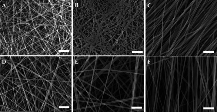
The scanning electron microscopy (SEM) images revealed that the collector had an impact on the morphology of the electrospun fibers. In addition to the morphology of the scaffold, the diameter of the fibers is also slightly affected by the rotating speed of the collector. The aligned nanofiber scaffolds fabricated using the same polymer solution and under the same electrospinning conditions (except the method of collection) show a slight decrease in the average diameter of the fibers. This phenomenon is attributed to the centrifugal forces from the rotating drum collector drawing the fibers out, as previously reported.13 As shown in Figure 1, the non-aligned nanofibers produced scaffolds with many more interconnected pores, compared to the aligned scaffolds. Moreover, the average fiber diameter (Figure S1) depends on the CS concentration. For instance, the average fiber diameter for both non-aligned and aligned C2P1 scaffolds ranged from 83 ± 10 to 137 ± 20 nm. On the other hand, it ranged from 134 ± 18 to 199 ± 30 nm for both non-aligned and aligned C4P1 scaffolds, which is obviously high compared to the C2P1 scaffolds. When the polymer concentration is increased, the chains of polymers within the liquid have more opportunity to become entangled, resulting in additional resistance against the liquid being stretched.32
Figure 1.
SEM micrographs of non-aligned (random) and aligned electrospun nanofibrous scaffolds showing the effect of various electrospinning processing parameters on the fiber diameter of the scaffolds. (A) R-R1-C2P1, (B) R-R4-C2P1, (C) A-R4-C2P1, (D) R-R1-C4P1, (E) R-R4-C4P1, and (F) A-R4-C4P1. The scale bar is 1 μm.
The pump flow rate is another factor which affects the fiber diameter. A low solution flow rate is needed to sustain the Taylor cone via the capillary force. By increasing the solution flow rate, the average fiber diameter increases for both the C2P1 and C4P1 scaffolds (Figure S2). The average fiber diameter increased from 83 ± 10 to 137 ± 20 nm in the case of C2P1 scaffolds and from 134 ± 18 to 199 ± 30 nm for the C4P1 scaffolds when the flow rate was increased from 0.006 to 0.024 mL/min. Furthermore, increasing the flow rate was associated with increasing the diameter of the fibers as a result of increasing the initial radius of the electrospinning jet, which indeed reduces the bending instability.33
Besides fiber diameter, the distribution of the pore size within the scaffolds and the mean flow pore (MFP) size were measured to correlate their values with the electrospinning parameters. The scaffold pore size was found to mainly be dependent on the scaffold fiber diameter and its packing density. The obtained data showed that the pore size of the CS/PEO nanofibrous scaffold was within the sub-micron range with values varying according to the surface topography. The MFP size for both non-aligned and aligned C2P1 scaffolds ranged from 563 ± 0.02 to 939 ± 0.07 nm, whereas the values ranged from 705 ± 0.1 nm to 1.49 ± 0.1 μm for the C4P1 scaffolds (Figure S3). The R-R4-C2P1 and R-R4-C4P1 scaffolds with the larger fiber diameter possess large-sized pores and low fiber packing density. Previous studies reported relevant data that support a direct relation between fiber diameters and pore size distribution.34 The aligned nanofibrous scaffold had densely packed fibers and a small pore size compared with the non-aligned scaffold; this phenomenon is attributed to the centrifugal forces from the rotating drum collector drawing the fibers in one consistent direction, thus conferring some orientation on them.13,35
The scaffold thickness was determined using a micrometer and the thickness for both non-aligned and aligned C2P1 scaffolds ranged from 19 ± 1.4 to 9 ± 1.4 μm, whereas the values ranged from 31 ± 1.4 to 16 ± 1.4 μm for the C4P1 scaffolds. From those, the scaffolds’ thicknesses are significantly decreased when the fiber deposition area increases due to raising the pump flow rate. Moreover, C4P1 scaffolds are thicker than C2P1 scaffolds produced under the same condition due to the high viscosity of CS solution, in addition to the low deposition area of C4P1 scaffolds.
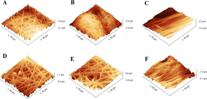
To determine the scaffold surface nanotopography, the surface roughness for both random and aligned scaffolds was calculated by analyzing a scanning area of 30 × 30 μm2 using atomic force microscopy (AFM) (Figure 2).
Figure 2.
3D AFM images of random and aligned electrospun nanofibrous scaffolds synthesized using two different solutions (C2P1 and C4P1) in addition to the effect of the pump flow rate on each of them. (A) R-R1-C2P1, (B) R-R4-C2P1, (C) A-R4-C2P1, (D) R-R1-C4P1, (E) R-R4-C4P1, and (F) A-R4-C4P1.
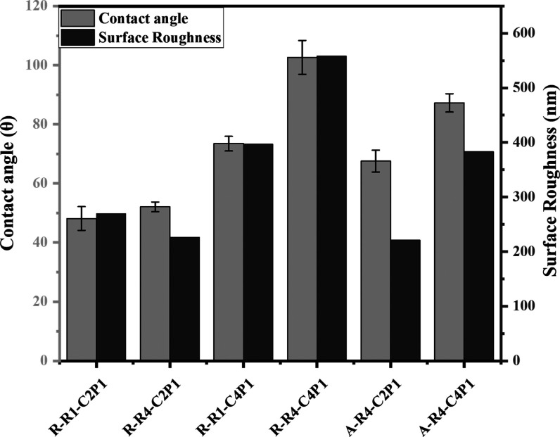
The AFM images offer a detailed comparison of average surface roughness for both types of scaffolds. The C2P1 scaffolds showed the smoothest surface with a roughness value of 158.46 and 294.81 nm for both non-aligned and aligned scaffolds, respectively. However, for C4P1 scaffolds, the roughness was high with values between 325.6 and 558.37 nm for both non-aligned and aligned scaffolds, respectively. The increase in surface roughness value for C4P1 scaffolds compared to C2P1 scaffolds could be due to the increase in the fiber diameter because of increasing the CS concentration and pump flow rate.36 However, the roughness of the R-R4-C2P1 scaffold was decreased due to the formation of cross-linked or fused fibers. The findings of the SEM measurements are consistent with AFM analysis. Moreover, the aligned nanofibrous scaffolds showed low surface roughness compared to the non-aligned ones, mainly due to the smaller fiber diameter and the formation of a surface with long parallel grooves.
The contact angles of the fabricated scaffolds were measured to evaluate their wettability. It was clear from the obtained data that the C4P1 scaffolds are more resistant to water adsorption than the C2P1 scaffolds (Figure 3). The contact angle values ranged from 48 ± 4 to 65.5 ± 3 for C2P1 scaffolds. In contrast, the values ranged from 73 ± 2 to 102 ± 5 for both CP41 scaffold types. The values of the contact angle are strongly affected by the roughness of a surface. Previous studies reported relevant data about the relation between the scaffold roughness and the measured contact angle.37
Figure 3.
Wettability and surface roughness of non-aligned and aligned electrospun nanofibrous scaffolds. The figure describes the effect of the CS concentration and pump flow rate on the surface wettability and roughness of the prepared scaffolds.
The Fourier transform infrared (FTIR) spectra of CS/PEO nanofibrous scaffolds (Figure S4) confirmed the successful mixing of CS with PEO polymers. The spectrum reflected a band at 3432 cm–1 which is attributed to the −OH group and the stretching vibration of the −NH2 bands of CS, whereas the peak at 2880 cm–1 originated from −CH2– stretching vibration of CS/PEO. Furthermore, the peaks at 1544 and 1645 cm–1 were due to the carbonyl stretching of the amide bands C=O–NH and the N–H bending of the CS amino groups, respectively. Another peak of CS (C–O stretching) was detected at 1029 cm–1 but overlapped with intense PEO bands of 1145, 1098, and 1035 cm–1 assigned to C–O–C stretching vibrations.38
2.2. Cell Morphology and Tissue Formation
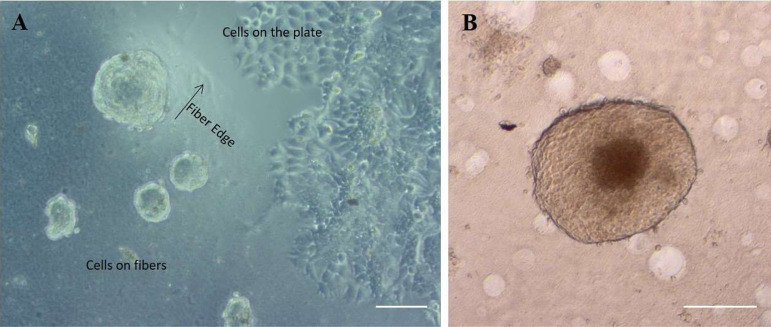
Human breast cancer cells (MCF-7) were cultured on all the six electrospun nanofibrous scaffolds as well as on ultra-low attachment plates (ULAPs) and adherent cell culture plates [tissue culture plate (TCP)]. It was obvious from the images obtained by optical microscopy that cells acquired different morphological behaviors dependent upon the basal surface they were grown on. For instance, cells cultured on adherent plates appeared to have a flattened, trigonal morphology and formed a confluent monolayer cell sheet. In contrast, on the surface of nanofibrous scaffolds, cells took on close to round structures which self-assemble to form aggregates. In addition, they were uniformly distributed on the surfaces of the scaffolds (Figure 4A). Typical spheroids have a spherical geometry with an outward proliferative zone, beyond which the innermost cells become quiescent (created by food and oxygen transport gradients) that surrounds a necrotic zone which dies because sufficient oxygen and fresh growth medium fail to diffuse far enough to reach them, imitating the cellular heterogeneity noticed in solid tumors, and the size of this spheroid had reached a diameter greater than 500 μm (Figure 4B).
Figure 4.
(A) Phase contrast image showing the difference in MCF-7 cell morphology at the interface between the C2P1 nanofibrous scaffolds and the plate bottom after 72 h in culture. The scale bar is 100 μm. (B) Optical image shows typically formed spheroid with three distinct zones. The scale bar is 200 μm.
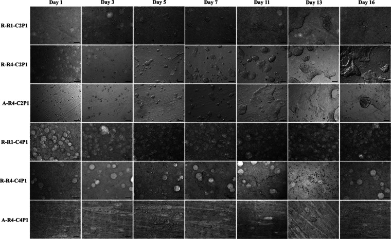
From day 3, a notable increase in cell number was observed, with the formation of numerous cell aggregates (Figure 5). The size of these aggregates increased from day to day, forming spheroids. Furthermore, spheroid formation was similar for both non-aligned and aligned nanofibrous scaffolds, which might be due to the possession of similar characteristics (roughness, fiber diameter, and wettability) within the same scaffold type (C2P1 and C4P1), but they did not show the same pattern when cultured on scaffolds with different CS concentrations.
Figure 5.
Optical images of MCF-7 cells seeded on non-aligned (R-R1-C2P1, R-R4-C2P1, R-R1-C4P1, and R-R4-C4P1) or aligned (A-R4-C2P1 and A-R4-C4P1) nanofibrous scaffolds after 16 days. The images show an increase in cell number and diameter of the formed spheroids until some of them form microtissues at day 10 of culture. The scale bar is 200 μm.
It was noticeable that MCF-7 cells cultured on the C2P1 scaffolds formed aggregates within the first 3 days of a culture that persisted up to 16 days of the experiment. These spheroids started to spontaneously fuse to form 3D breast cancer microtissues after 10 days of culture without the introduction of external growth factors (Figure 5). On the other hand, cells cultured on C4P1 scaffolds formed spheroids at the same time, but quickly disassociated from 8 to 10 days of time in culture (Figure 5). As mentioned before, the CS content within the two types of nanofibrous scaffolds was different; therefore, we suggest that not only the morphological characteristics of the scaffolds are crucial to determine the cell proliferation but also the CS content in those scaffolds.
2.3. Number and Distribution of Spheroids
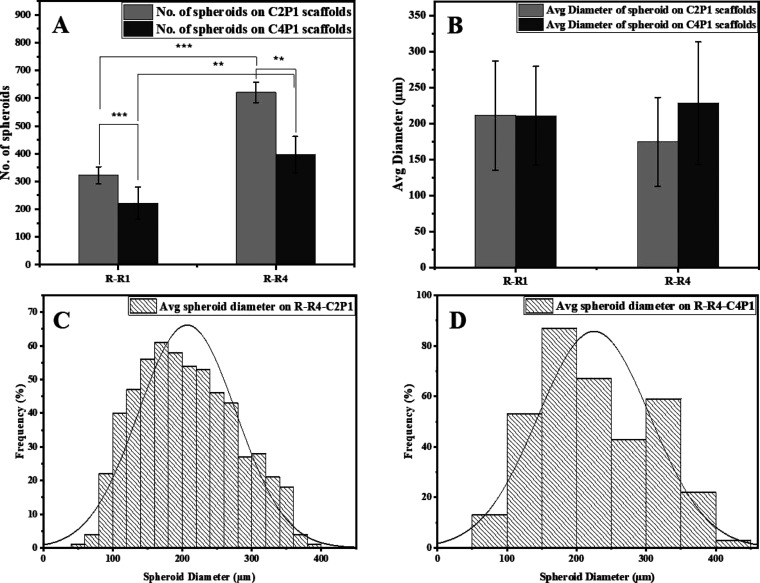
In order to understand the behavior of MCF-7 breast cancer cells in response to the surface topography of four different scaffolds, it was necessary to correlate the number of spheroids formed in the early stage of culture to the scaffold characteristics. After 7 days of culture, the formation of MCF-7 spheroids was captured by an optical microscope and analyzed to quantify their number and diameter. As shown in Figure 6A, the numbers of spheroids formed on the C2P1 scaffolds were significantly higher compared to the numbers of spheroids formed on C4P1 scaffolds. It was also clear that surface topography of the scaffolds can influence the formation of spheroids, where the number of spheroids formed on the R-R1-C2P1 scaffold was 322 ± 31 spheroids per well, but the spheroid number increased to 621 ± 36 spheroids per well on the R-R4-C2P1 scaffold. Similarly, the number of spheroids on C4P1 scaffolds increased on the R-R4-C4P1 scaffold (397 ± 65 spheroids per well) compared to the R-R1-C4P1 scaffold (222 ± 57 spheroids per well).
Figure 6.
Effects of scaffold surface topography on MCF-7 spheroid formation. (A) Number of MCF-7 spheroids formed on R-R1 and R-R4 for the C2P1 and C4P1 scaffolds after 7 days of culturing. (B) Average spheroid diameter on R-R1 and R-R4 for the C2P1 and C4P1 scaffolds. (C,D) Histograms show spheroid size distribution on R-R4 of C2P1 and C4P1 scaffolds, respectively.
The high spheroid numbers counted on R-R4-C2P1 and R-R4-C4P1 scaffold surfaces could be due to the large fiber diameter, pore size, and small packing density which led to better cell proliferation. The scaffolds with large pores permit cell infiltration and migration allowing cells to reach the scaffolds’ depth and proliferate; this is to facilitate nutrient and oxygen exchange leading to the increase of spheroid numbers.25,39 However, in the case of scaffolds (R-R1-C2P1 and R-R1-C4P1) with high packing density, only the surface of the scaffolds is available for cell proliferation. The surface roughness, fiber diameter, pore size, and wettability were known to influence the cell adhesiveness and cell spreading capability.40 Furthermore, CS has been reported to be mucoadhesive,41 so the C2P1 scaffolds are more favorable for spheroid formation than the C4P1 scaffolds which are more adhesive. Differences in CS concentration influence the scaffolds’ surface charge as CS has a positive charge due to the amine group. When the concentration increases the positive charge at the surface, the zeta potential increases and affects the formation and stability of the formed 3D spheroids.42
On the other hand, the average diameter of MCF-7 spheroids grown on C2P1 and C4P1 scaffolds was not affected by surface topography as spheroids’ diameter ranged from 211 ± 76 to 174.9 ± 61 μm for C2P1 scaffolds and from 211 ± 68 to 228.2 ± 85 μm for C4P1 scaffolds (Figure 6B). This means that surface topography has a great impact on the number of spheroids formed but not on their diameter (Figure 6C,D). Besides differences in the number of spheroids in the first week, no obvious morphological differences could be recognized among the spheroids formed on the C2P1 and C4P1 scaffolds within this week.
2.4. Cell Viability
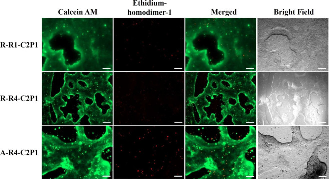
In order to evaluate MCF-7 cell viability on all the six nanofibrous scaffolds, we carried out a cell viability assay using calcein AM and ethidium homodimer-1 staining. Figure 7 shows an intense green fluorescence signal (living cells) and a very weak red fluorescence signal (dead cells) on C2P1 scaffolds, indicating the high viability of cells within the 3D microtissues after 17 days of incubation time. This indicates the possible involvement of cell migration to form compact 3D breast cancer microtissues.
Figure 7.
Fluorescence images of MCF-7 cell tissue viability assessment on randomly (R-R1-C2P1, R-R4-C2P1) and aligned (A-R4-C2P1) C2P1 scaffolds after 17 days. Calcein AM (green) stains the living cells whereas ethidium homodimer-1 (red) stains the dead cells. The scale bar is 200 μm.
The 3D breast cancer microtissues displayed good cell viability without apparent death. Most dead cells are single cells that lost their viability and remained outside the viable 3D breast cancer microtissues after they died. As discussed above, the CS concentration was observed to impact the overall viability of the growing spheroids and their stability on the nanofibrous scaffolds within the first 8–10 days. After that time point, we no longer observed any significant difference in viability and morphology of the MCF-7 breast cancer microtissues formed on C2P1 scaffolds for the non-aligned and aligned fibers. This is most likely due to all the scaffolds’ surface topographies promoting cell–cell interactions instead of cell–matrix ones, resulting in the formation of spheroids maturing into 3D breast cancer microtissues. Another reason is that no much difference in values of the scaffold surface topography was observed, and we found that the huge difference was between C2P1 and C4P1 scaffolds not between random and aligned scaffolds of the same concentration.
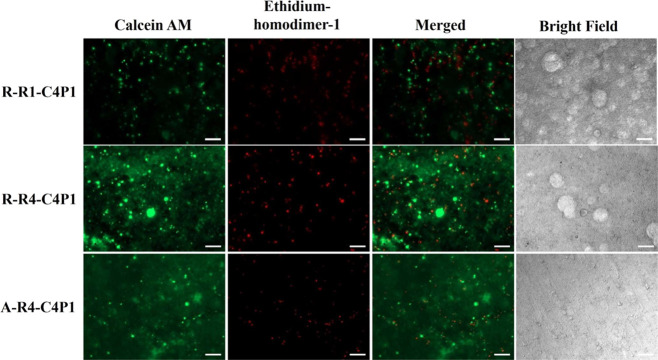
In contrast to the C2P1 scaffolds, the C4P1 scaffolds showed an intense red fluorescence signal, indicating pronounced cell death, and a weak green fluorescence signal from the cells remaining on the surfaces (Figure 8) due to dissociation of the formed spheroids after 17 days of seeding. Varying the conditions used to create C4P1 scaffolds had no effect on spheroid formation, viability, or the formation of 3D breast cancer microtissues.
Figure 8.
Fluorescence images of MCF-7 cell viability assessment of non-aligned (R-R1-C4P1 and R-R4-C4P1) and aligned (A-R4-C4P1) C4P1 scaffolds after 17 days. Calcein AM (green) stains the living cells whereas ethidium homodimer-1 (red) stains the dead cells. The scale bar is 200 μm.
Interestingly, the size, shape, and viability of the 3D cancer microtissues formed on C2P1 scaffolds was better than that of spheroids formed by using a commercially available ULAP. In our case, using an ULAP, the size of the MCF-7 spheroids increased with the incubation time and exhibited a diameter of 522 μm over 17 days of culture with good cell viability (Figure S5). However, cell culture on the TCP showed an intense red fluorescence signal, indicating vast cell death due to a long time of incubation which leads to cell stress and death after 17 days of culturing (Figure S6).
2.5. Cell Proliferation
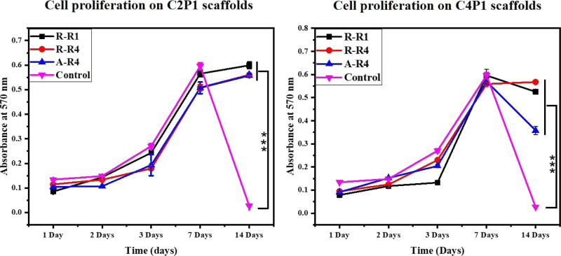
A series of 3-(4,5-dimethylthiazol-2-yl)-2,5-diphenyltetrazolium bromide (MTT) assays were performed to determine the proliferation of MCF-7 cells after 1, 2, 3, 7, and 14 days of culture. In this experiment, a TCP was used as the negative control. The CS/PEO nanofibrous scaffolds effectively support cell adhesion and proliferation, and CS and PEO are highly biocompatible materials.43 The MCF-7 cells were followed over a 14 day time course. Cell viability for all six scaffolds was about the same value during the first week of the experiment (Figure 9).
Figure 9.
Proliferation of MCF-7 cells cultured on the tested scaffolds compared to standard tissue culture plates used as the control.
On day 7 of the culture, cells reached a plateau and stopped growing at an exponential rate. Strikingly, cultures grown on TCP completely died in the second week of the experiment but remained viable when grown on nanofibrous scaffolds. C2P1 scaffolds were slightly superior in supporting cell growth compared to C4P1, on which viability also declined in the second week of culture.
Considering the cell seeding densities were the same in nanofibrous scaffolds (C2P1 and C4P1) and TCP, the difference might result from the expanded space (large surface area compared to the volume) for cell growth in CS/PEO nanofibrous scaffolds. In addition, the porous morphology and large surface area of the nanofibrous scaffolds may have assisted tissue oxygenation resulting in enhanced cell adhesion, spreading, and proliferation like in vivo structures do.44
2.6. Microscopy of MCF7 Cells on Nanofibrous Scaffolds
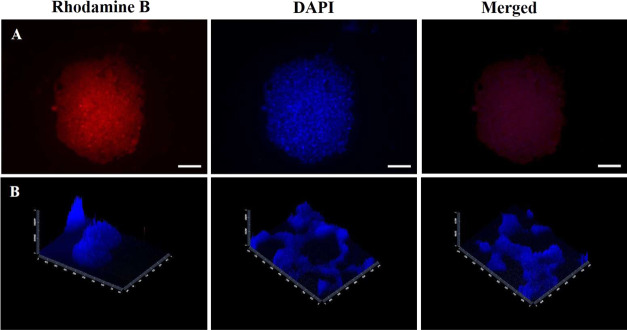
Fluorescence images reveal cell morphology grown on nanofibrous scaffolds at different culture times. The taken images show that cells on nanofibrous scaffolds exhibited a round shuttle-like shape which self-assembled with each other to form 3D spheroids (Figure 10A).
Figure 10.
(A) Fluorescence images of MCF-7 spheroid cytoskeleton stained with rhodamine-B and spheroid nuclei stained with DAPI formed on C2P1 scaffolds. (B) Z-stack images of the formed spheroids and 3D microtissue nuclei stained with DAPI. The scale bar is 100 μm.
Morphological analysis demonstrated the presence of specific sites of intercellular connections in addition to the discontinuous areas where plasma membranes of adjacent cells were in adhesive contact which indicate cell–cell connections. Furthermore, Z-sections were able to be imaged for the nanofibrous scaffolds to analyze how cells interact with each other and with their microenvironment in all three spatial dimensions. Furthermore, it shows how 3D microtissues engulf the nanofiber surface (Figure 10B).
2.7. Scanning Electron Microscopy
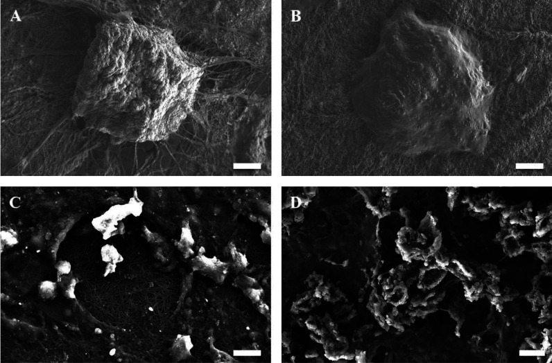
SEM images display that the formed spheroids have a smooth surface, tight cell junctions, and indistinguishable cellular boundaries with interweaving of the fibers into and around the spheroids and the 3D microtissues that assist in anchoring and stabilization (Figure 11). Both morphological forms exhibit cell–scaffold and cell–cell interactions.
Figure 11.
SEM images of the spheroids (A,B) and 3D microtissues (C,D) formed on the surface of C2P1 nanofibrous scaffolds at different culture times. The scale bar is 20 and 10 μm.
2.8. Immunofluorescence Staining
Ki-67 (green) was used to determine the proliferative potential and growth of the cells in the microtissues formed after 27 days of culture on the two randomly C2P1 scaffolds, using DAPI (blue) to stain and visualize the nuclei of the cells (Figure 12). Ki-67 is highly expressed in the microtissues but not in the 2D monolayer, highlighting the high proliferative activity of cells in the 3D microtissues. Essentially, these types of morphological differences resemble the microenvironment of the in vivo tumor, where cells are generally present as multicellular proliferative clusters.
Figure 12.
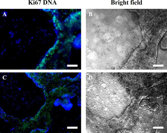
Fluorescence images of immunofluorescence staining for MCF-7 3D microtissues formed after 27 days of culturing on non-aligned (randomly oriented) nanofibrous scaffolds [(A, B-R-R1-C2P1) and (C, D-R-R4-C2P1)]. (A,C) Merged images of anti-Ki-67 (green) and DAPI (blue) stains of the nuclei and (B,D) bright field images. Ki-67 expression is limited to the 3D microtissues but not in the 2D monolayer. The scale bar is 200 μm.
Ki-67 showed that most cells were actively proliferating within the microtissues formed after 27 days of incubation time, which indicates that a lot of cells within the microtissues are healthy and continue to proliferate. On the other hand, a small number of quiescent, non-proliferating but viable cells are present, which resemble the situation in vivo in cancer microtissues. Ki-67 is highly expressed in the microtissues but not in the 2D monolayer, highlighting the high proliferative activity of cells in the 3D microtissues.
2.9. Mechanism of 3D Tissue Formation
The surface topography of the CS/PEO scaffolds discussed above plays an essential role in the behavior of tumor cells and the spontaneous formation of the breast cancer microtissues that resemble in vivo cancer tissues. The dimensions and morphology of CS/PEO nanofibrous scaffolds resemble the nano- and sub-micron scale of ECM structures in the in vivo tumor microenvironment.45 The characteristics and surface topography of these scaffolds induce spheroid formation and the development of microtissues by mechanisms which are currently not completely understood but we suppose the following possibilities as potential mechanisms for the formation: (i) cell–cell interactions result in tight cell aggregates which form the spheroid through self-assembly and then the formed spheroids are held together forming the 3D microtissues and (ii) outward proliferation of a fiber-attached cell to form a spheroid which enlarges in size and proliferates more and more forming the 3D microtissues. We found that cells cultured on C4P1 scaffolds formed spheroids that quickly dissociated within 8–10 days of culturing, whereas cells grown on C2P1 scaffolds first formed spheroids and then 3D microtissues which persisted for the duration of culture. Moreover, the number of spheroids on the same type of scaffolds depended on the conditions used when creating the scaffold. We show that the pore size, roughness, packing density, and fiber diameter of the C2P1 scaffolds create a surface topography that is very suitable for the stable and spontaneous formation of microtissues. In addition, these scaffolds have a suitable balance of hydrophobicity and hydrophilicity which facilitates the formation of tumor spheroids.23,46
Based on our observations, each spheroid forms a number of elongated extensions or protrusions out of the spheroid structure and makes contact with scaffold surfaces (Figure S8). These finger-like protrusions resemble those produced by cancer cells penetrating the ventral membrane during the initial stages of the migration of metastases. They are considered as matrix-degrading structures involved in ECM proteolysis.47 The formation of this protrusion confirms that CS/PEO scaffolds act as ECM for the MCF-7 cells without the need for external growth factors. Also, this protrusion plays an important role in directing cell migration and leads to the metastases of cancer cells.48 The spheroids start migrating to fuse with each other and form breast cancer microtissues, which is a mechanically strong structure. The breast cancer microtissues display good cell viability and bioactivity, especially for a long culture time on all C2P1 scaffolds and a number of dead cells diffuse out of the 3D microtissues.
Most studies currently rely on mechanical spheroid formation involving a method using a specific inverted cone-shaped, non-adherent culture dish by rotating, shaking, and stirring motions.49 In our case, we found that by using exactly the right materials and conditions, we were able to generate spontaneously formed spheroids which did not rely on mechanical manipulation. The mechanically formed spheroids have a short life span whereas the spontaneously formed spheroids go on to form mechanically strong cancer microtissues. Previously, spheroid formation was reported to take 5–10 days,50 or as much as several weeks on polymer-based scaffolds, or through serum-free medium with a specific growth factor [epidermal growth factor, basic fibroblast growth factor, B27 minus, vitamin A (Invitrogen), and Lif1];51 however, here rapid spheroid formation was observed on the CS/PEO scaffolds after merely 48–72 h in the absence of external growth factors.
The creation of spontaneously formed 3D cancer microtissues is an important step in drug screening and development. The 3D cultures have far fewer interactions between cells and the scaffolds so that cell migration on the scaffold surface is apparently easier and cell–cell interactions are facilitated. Taken together, the balance between cell–cell and cell–scaffold interactions affects cell adhesion, viability, and migration on the scaffold surfaces. The evidence for the low level of interaction between MCF-7 cells and the scaffolds is that the cells are not affected by the degree of alignment of the nanofibers.
3. Conclusions
3D breast cancer cell culture on CS/PEO nanofibrous scaffolds is one effective, high-profile, and proactive cell culture platform compared to the TCP and other 3D cell cultures such as ULAPs. The network structure of nanofibrous scaffolds can imitate the native ECM microenvironment of the in vivo tumor. Therefore, the surface topography of CS/PEO scaffolds was varied in order to determine the behavior of MCF-7 breast cancer cells on these surfaces. Different scaffold surface topographies were produced by changing the electrospinning processing parameters such as the polymer concentration, pump flow rate, and method of collection. Based on our results, as the polymer concentration and pump flow rate increase, the fiber diameter, pore size, hydrophobicity, and surface roughness increases.
CS/PEO nanofibrous scaffolds sustained cell viability and active cell growth for at least 17 days. The scaffold surface topography affects the tumor cells’ behavior. C2P1 scaffolds formed a higher number of spheroids and formed more breast cancer microtissues than C4P1 scaffolds. Whether the fibers were specifically aligned or not made no appreciable difference for C2P1 scaffolds with regard to the formation of 3D breast cancer microtissues.
Our platform is a simple and low-cost fabrication method. Although, the cancer phenotype has not been studied thoroughly, these scaffolds offering cancer cells a natural microenvironment with non-toxic components and FDA approved. Besides, the fabrication hypothesis is formed without the use of potentially hazardous chemicals. The novel in this platform is the formation of stable and reproducible 3D tissue-like structures which did not stop at the stage of forming spheroids as mentioned in the literature. The obtained 3D tissue-like structures will be used as a drug screening and development platform, which will lead to results that mimic the in vivo one.
4. Experimental Section
4.1. Scaffold Fabrication
CS/PEO nanofibrous scaffolds were manufactured via electrospinning. In detail, CS solutions were prepared by dissolving CS powder with an average molecular weight of 200,000 g/mol (International Laboratory, USA) in 90% glacial acetic acid (AA 99%, Chem-Lab, Belgium). CS solutions of 2 and 4 wt % were prepared by continuous and vigorous stirring overnight at room temperature. A separate solution of PEO was prepared by dissolving PEO with an average molecular weight of 600,000 g/mol (Sigma-Aldrich, USA) in glacial acetic acid under the same conditions used with CS. The solutions were mixed at a ratio of 3:1 CS to PEO, producing C2P1 (2 wt % CS) and C4P1 (4 wt % CS) solutions (Table 1). Each of the blended solutions was then placed in a 5 mL syringe with a 21 gauge blunt tip. The polymer was ejected using a syringe pump (KD Scientific, Holliston, MA, USA) at a flow rate of 0.006–0.024 mL/min. The complete set of experiments is represented in Table 1 with employing varied electrospinning processing parameters.
Table 1. Summary of the Different Electrospinning Processing Parameters Used in Our Study.
| sample name | CS (wt %) | PEO (wt %) | solution ratio (CS/PEO) | dry ratio (CS/PEO) | flow rate (mL/min) | voltage (kV) | distance (cm) |
|---|---|---|---|---|---|---|---|
| R-R1-C2P1 | 2 | 3 | 3:1 | 2:1 | 0.006 | 19 | 20.5 |
| R-R4-C2P1 | 2 | 3 | 3:1 | 2:1 | 0.024 | 19 | 20.5 |
| A-R4-C2P1 | 2 | 3 | 3:1 | 2:1 | 0.024 | 19 | 9 |
| R-R1-C4P1 | 4 | 3 | 3:1 | 4:1 | 0.006 | 19 | 20.5 |
| R-R4-C4P1 | 4 | 3 | 3:1 | 4:1 | 0.024 | 19 | 20.5 |
| A-R4-C4P1 | 4 | 3 | 3:1 | 4:1 | 0.024 | 19 | 9 |
For collecting non-aligned nanofibers, a stationary grounded collector covered with aluminum foil was placed at a distance of 20 cm from the tip of the nozzle. Aligned nanofibers were prepared by placing a drum collector at a distance of 9 cm from the tip of the nozzle rotating at 2000 rpm (Table 1). A voltage of 19 kV was applied between the nozzle tip and the stationary/drum collector.
4.2. Scaffold Characterization
Microstructure and morphology of the electrospun CS/PEO nanofibers were analyzed using a scanning electron microscope (Carl Zeiss Sigma 500 VP, Jena, Germany) operated at an acceleration voltage of 10 kV. Before the SEM examination, the samples were coated with gold for 1 min. ImageJ software was used to analyze the average fiber diameter.
The scaffold pore size was measured by capillary flow porometry (POROLUX 1000 Porometer, IB-FT GmbH, Berlin, Germany). Porefil wetting fluid was applied to wet the scaffold when the sample was pressurized under air to an applied pressure of 3 bar. The bubble point and average pore size were determined.
The surface topography and morphology of the scaffolds were analyzed using an atomic force microscope (Nanosurf Flex, Liestal, CH). The thin nanofibrous scaffolds were affixed onto the atomic force microscope holder using a double-sided tape. The measurements were performed at room temperature in the tapping mode using an aluminum–gold tip at a resonance frequency of 190 kHz. NanoSurf Easy Scan software was used to calculate the root mean square and surface roughness of the 30 × 30 μm2 scanning area.
To assess the scaffolds’ hydrophilicity, the contact angle was measured using the contact angle measuring system (OCA 25, DataPhysics GmbH, Germany). In detail, 10 μL of deionized water was dropped on top of the scaffolds. Then, high-resolution images were captured after 5 s of incubation and the average contact angle was calculated based on five measurements at different locations.
FTIR measurements were carried out to investigate the functional groups of CS/PEO electrospun nanofibrous scaffolds. Absorption spectra were recorded in the energy range of 500–4000 cm–1 using a Bruker Vertex 70 spectrophotometer (Billerica, MA, USA) coupled with a diamond attenuated total reflection unit.
4.3. Cell Culture
Human breast cancer cell line MCF-7 was obtained from the American Type Culture Collection (ATCC; Rockville, MD, USA). Cells were cultured in Dulbecco’s modified Eagle’s medium high glucose (4,500 mg/L d-glucose anhydrous) and supplemented with 10% FBS, 50 U/mL penicillin, 50 μg/mL streptomycin, and 1% l-glutamine (Biowest, Nuaillé, France). The cells were maintained in a 5% CO2 humidified incubator at 37 °C.
The electrospun nanofibrous scaffolds were cut into discs using a hole puncher with 6.4 mm internal diameter. The discs were sterilized for 20 min at 120 °C in a drying oven and then sprayed with 70% ethanol/water and exposed to UV irradiation for 2 h. The nanofibrous scaffolds were soaked in media overnight before cell seeding. Then, 200 μL of a MCF-7 human breast cancer cell suspension was added to each well (3,500 cells/well) of a 96-well plate.
4.4. Cell Proliferation Assay
The MTT assay was applied to test the cell proliferation on the fabricated scaffolds and non-coated cell culture plates. Only viable cells retain the ability to transform the yellow tetrazolium salt into water-insoluble purple crystals of formazan. The scaffolds were cut into discs using a hole puncher with 16 mm internal diameter and then placed into new wells of 24-well plates and sterilized with the protocol mentioned in the previous section. Thereafter, a suspension of 40,000 MCF-7 cells was seeded in each well. Cell culture was maintained for 14 days. After 24, 48, 72 h, 1, and 2 weeks, samples were collected and the MTT assay was performed. Briefly, the scaffolds and adherent wells were first washed with phosphate-buffered saline (PBS), then treated with 1 mL of Dulbecco’s modified Eagle’s medium and 200 μL of MTT and incubated for 4 h. Next, 750 μL of sodium dodecyl sulfate was added to dissolve the formazan crystals. Three 100 μL aliquots from each well were transferred into a 96-well plate and the absorbance was measured at 570 nm using a microplate reader (800 TS microplate absorbance reader, BioTek Instruments, USA).
4.5. Spheroid Diameter and Number Estimation
The number of spheroids resulting from a suspension of 40,000 MCF-7 cells seeded into 24-well plates was counted from complete planar images taken systematically across each scaffold. Formed rounded aggregates of size greater than 50 μm were counted as spheroids. For the measurement of spheroid diameter, all-optical images were taken of each scaffold with an inverted fluorescence microscope (Axio Vert.A1, Carl Zeiss, Oberkochen, Germany) and analyzed using ZEN 2 (blue edition) software (Carl Zeiss).
4.6. Cell Viability Assay
The cell viability assay of MCF-7 cells was performed using the viability/cytotoxicity kit (Thermo Fisher Scientific, Waltham, MA, USA), as per the manufacturer’s instructions. Briefly, the cells were stained with 2 μM calcein AM and 2 μM ethidium homodimer-1 diluted in 1× RPMI 1640 for 15 min at 37 °C. Images were taken using an inverted fluorescence microscope.
4.7. Immunofluorescence Staining
To observe the proliferating nuclei within the grown 3D microtissues on C2P1 nanofibrous scaffolds, samples were stained with Ki-67. In brief, after culturing for 27 days, the cell nuclei on the scaffolds were fixed with 4% paraformaldehyde for 15 min. Then, samples were permeabilized with 0.5% Triton X-100 for 15 min and washed with PBS three times. The cells were then blocked in 1% bovine serum albumin solution for 30 min, followed by washing three times with PBS. Finally, the nuclei of cells were stained with anti-Ki-67 and DAPI for 20 min and observed using a fluorescence microscope.
4.8. Statistical Analysis
All experiments were done in triplicate. Data are reported as the average ± standard deviation. Results were analyzed using SPSS software version 16.0 with Student’s t-test and ANOVA to study the effect of scaffolds with different surface topography on the cancer cell proliferation and number of spheroids formed on their surface. One star (*) means a p-value < 0.05, two stars (**) mean a p-value < 0.01, and three stars (***) mean a p-value < 0.001.Corresponding Author Ahmed S. G. Khalil:asg05@fayoum.edu.eg Co-authors: Amna M. I. Rabie: am1329@fayoum.edu.eg Ahmed S. M. Ali: as1215@fayoum.edu.eg Munir A. Al-Zeer: al-zeer@tu-berlin.de Ahmed Barhoum: ahmed.barhoum@science.helwan.edu.eg Salwa EL-Hallouty: hallouty68@gmail.com Wafaa G. Shousha: wafaashousha@gmail.com Johan
Acknowledgments
A.S.G.K. acknowledges the financial support from the Arab-German Young Academy for Sciences and Humanities (AGYA), Germany.
Supporting Information Available
The Supporting Information is available free of charge at https://pubs.acs.org/doi/10.1021/acsomega.1c05646.
Scaffold characterization as the distribution of fiber diameter; main flow pore size; FTIR spectra; optical images of the control and its cell viability; and images of the spheroid and 3D microtissue protrusions (PDF)
The authors declare no competing financial interest.
Supplementary Material
References
- Bahcecioglu G.; Basara G.; Ellis B. W.; Ren X.; Zorlutuna P. Breast cancer models: Engineering the tumor microenvironment. Acta Biomater. 2020, 106, 1–21. 10.1016/j.actbio.2020.02.006. [DOI] [PMC free article] [PubMed] [Google Scholar]
- Kapałczyńska M.; Kolenda T.; Przybyła W.; Zajączkowska M.; Teresiak A.; Filas V.; Ibbs M.; Bliźniak R.; Łuczewski Ł.; Lamperska K. 2D and 3D cell cultures–a comparison of different types of cancer cell cultures. Arch. Med. Sci. 2018, 14, 910. 10.5114/aoms.2016.63743. [DOI] [PMC free article] [PubMed] [Google Scholar]
- Katt M. E.; Placone A. L.; Wong A. D.; Xu Z. S.; Searson P. C. In vitro tumor models: advantages, disadvantages, variables, and selecting the right platform. Front. Bioeng. Biotechnol. 2016, 4, 12. 10.3389/fbioe.2016.00012. [DOI] [PMC free article] [PubMed] [Google Scholar]
- Sawy A. M.; Barhoum A.; Gaber S. A. A.; El-Hallouty S. M.; Shousha W. G.; Maarouf A. A.; Khalil A. S. G. Insights of doxorubicin loaded graphene quantum dots: Synthesis, DFT drug interactions, and cytotoxicity. Mater. Sci. Eng., C 2021, 122, 111921. 10.1016/j.msec.2021.111921. [DOI] [PubMed] [Google Scholar]
- Zanoni M.; Piccinini F.; Arienti C.; Zamagni A.; Santi S.; Polico R.; Bevilacqua A.; Tesei A. 3D tumor spheroid models for in vitro therapeutic screening: a systematic approach to enhance the biological relevance of data obtained. Sci. Rep. 2016, 6, 19103. 10.1038/srep19103. [DOI] [PMC free article] [PubMed] [Google Scholar]
- Sacchi M.; Bansal R.; Rouwkema J. Bioengineered 3d models to recapitulate tissue fibrosis. Trends Biotechnol. 2020, 38, 623–636. 10.1016/j.tibtech.2019.12.010. [DOI] [PubMed] [Google Scholar]
- Hoarau-Véchot J.; Rafii A.; Touboul C.; Pasquier J. Halfway between 2D and animal models: are 3D cultures the ideal tool to study cancer-microenvironment interactions?. Int. J. Mol. Sci. 2018, 19, 181. 10.3390/ijms19010181. [DOI] [PMC free article] [PubMed] [Google Scholar]
- De León S. E.; Pupovac A.; McArthur S. L. Three-Dimensional (3D) cell culture monitoring: Opportunities and challenges for impedance spectroscopy. Biotechnol. Bioeng. 2020, 117, 1230–1240. 10.1002/bit.27270. [DOI] [PubMed] [Google Scholar]
- Rijal G.; Li W. A versatile 3D tissue matrix scaffold system for tumor modeling and drug screening. Sci. Adv. 2017, 3, e1700764 10.1126/sciadv.1700764. [DOI] [PMC free article] [PubMed] [Google Scholar]
- Liu T.; Chien C.-C.; Parkinson L.; Thierry B. Advanced micromachining of concave microwells for long term on-chip culture of multicellular tumor spheroids. ACS Appl. Mater. Interfaces 2014, 6, 8090–8097. 10.1021/am500367h. [DOI] [PubMed] [Google Scholar]; a Zhao Y.; Xiong J.; Shi X.; Ko F. Capturing cancer cells using hyaluronic acid-immobilized electrospun random or aligned PLA nanofibers. Colloids Surf., A 2019, 583, 123978. 10.1016/j.colsurfa.2019.123978. [DOI] [Google Scholar]
- Nam K.-H.; Smith A. S. T.; Lone S.; Kwon S.; Kim D.-H. Biomimetic 3D tissue models for advanced high-throughput drug screening. J. Lab. Autom. 2015, 20, 201–215. 10.1177/2211068214557813. [DOI] [PMC free article] [PubMed] [Google Scholar]
- Baptista L.; Kronemberger G.; Côrtes I.; Charelli L.; Matsui R.; Palhares T.; Sohier J.; Rossi A.; Granjeiro J. Adult stem cells spheroids to optimize cell colonization in scaffolds for cartilage and bone tissue engineering. Int. J. Mol. Sci. 2018, 19, 1285. 10.3390/ijms19051285. [DOI] [PMC free article] [PubMed] [Google Scholar]
- Stachewicz U.; Qiao T.; Rawlinson S. C. F.; Almeida F. V.; Li W.-Q.; Cattell M.; Barber A. H. 3D imaging of cell interactions with electrospun PLGA nanofiber membranes for bone regeneration. Acta Biomater. 2015, 27, 88–100. 10.1016/j.actbio.2015.09.003. [DOI] [PubMed] [Google Scholar]
- Yap K. K.; Dingle A. M.; Palmer J. A.; Dhillon R. S.; Lokmic Z.; Penington A. J.; Yeoh G. C.; Morrison W. A.; Mitchell G. M. Enhanced liver progenitor cell survival and differentiation in vivo by spheroid implantation in a vascularized tissue engineering chamber. Biomaterials 2013, 34, 3992–4001. 10.1016/j.biomaterials.2013.02.011. [DOI] [PubMed] [Google Scholar]; a Park S. M.; Lee S. J.; Lim J.; Kim B. C.; Han S. J.; Kim D. S. Versatile Fabrication of Size-and Shape-Controllable Nanofibrous Concave Microwells for Cell Spheroid Formation. ACS Appl. Mater. Interfaces 2018, 10, 37878–37885. 10.1021/acsami.8b15821. [DOI] [PubMed] [Google Scholar]
- Song H.; Cai G.-h.; Liang J.; Ao D.-s.; Wang H.; Yang Z.-h. Three-dimensional culture and clinical drug responses of a highly metastatic human ovarian cancer HO-8910PM cells in nanofibrous microenvironments of three hydrogel biomaterials. J. Nanobiotechnol. 2020, 18, 90. 10.1186/s12951-020-00646-x. [DOI] [PMC free article] [PubMed] [Google Scholar]
- Benatti A. C. B.; Pattaro A. F.; Rodrigues A. A.; Xavier M. V.; Kaasi A.; Barbosa M. I. R.; Jardini A. L.; Filho R. M.; Kharmandayan P.. Bioreabsorbable polymers for tissue engineering: PLA, PGA, and their copolymers. In Materials for Biomedical Engineering; Holban A.-M., Grumezescu A. M., Eds.; Elsevier, 2019; Chapter 4, pp 83–116. [Google Scholar]
- Fisher M. F.; Rao S. S. Three-dimensional culture models to study drug resistance in breast cancer. Biotechnol. Bioeng. 2020, 117, 2262–2278. 10.1002/bit.27356. [DOI] [PubMed] [Google Scholar]; a Montanez-Sauri S. I.; Beebe D. J.; Sung K. E. Microscale screening systems for 3D cellular microenvironments: platforms, advances, and challenges. Cell. Mol. Life Sci. 2015, 72, 237–249. 10.1007/s00018-014-1738-5. [DOI] [PMC free article] [PubMed] [Google Scholar]
- Langhans S. A. Three-dimensional in vitro cell culture models in drug discovery and drug repositioning. Front. Pharmacol. 2018, 9, 6. 10.3389/fphar.2018.00006. [DOI] [PMC free article] [PubMed] [Google Scholar]; a Panek M.; Grabacka M.; Pierzchalska M. The formation of intestinal organoids in a hanging drop culture. Cytotechnology 2018, 70, 1085–1095. 10.1007/s10616-018-0194-8. [DOI] [PMC free article] [PubMed] [Google Scholar]
- Shao C.; Chi J.; Zhang H.; Fan Q.; Zhao Y.; Ye F. Development of cell spheroids by advanced technologies. Adv. Mater. Technol. 2020, 5, 2000183. 10.1002/admt.202000183. [DOI] [Google Scholar]
- Qasim S.; Zafar M.; Najeeb S.; Khurshid Z.; Shah A.; Husain S.; Rehman I. Electrospinning of chitosan-based solutions for tissue engineering and regenerative medicine. Int. J. Mol. Sci. 2018, 19, 407. 10.3390/ijms19020407. [DOI] [PMC free article] [PubMed] [Google Scholar]; a Ahmed S.; Annu; Ali A.; Sheikh J. A review on chitosan centred scaffolds and their applications in tissue engineering. Int. J. Biol. Macromol. 2018, 116, 849–862. 10.1016/j.ijbiomac.2018.04.176. [DOI] [PubMed] [Google Scholar]; b Qu F.; Holloway J. L.; Esterhai J. L.; Burdick J. A.; Mauck R. L. Programmed biomolecule delivery to enable and direct cell migration for connective tissue repair. Nat. Commun. 2017, 8, 1780. 10.1038/s41467-017-01955-w. [DOI] [PMC free article] [PubMed] [Google Scholar]
- Cavo M.; Serio F.; Kale N. R.; D’Amone E.; Gigli G.; del Mercato L. L. Electrospun nanofibers in cancer research: from engineering of in vitro 3D cancer models to therapy. Biomater. Sci. 2020, 8, 4887–4905. 10.1039/d0bm00390e. [DOI] [PubMed] [Google Scholar]
- Guduric V.; Fénelon M.; Fricain J.-C.; Catros S.. Membrane scaffolds for 3D cell culture. In Current Trends and Future Developments on (Bio-) Membranes; Basile A., Annesini M. C., Piemonte V., Charcosset C., Eds.; Elsevier, 2020; Chapter 7, pp 157–189. [Google Scholar]; a Wu T.; Mo X.; Xia Y. Moving Electrospun Nanofibers and Bioprinted Scaffolds toward Translational Applications. Adv. Healthcare Mater. 2020, 9, 1901761. 10.1002/adhm.201901761. [DOI] [PMC free article] [PubMed] [Google Scholar]
- Girard Y. K.; Wang C.; Ravi S.; Howell M. C.; Mallela J.; Alibrahim M.; Green R.; Hellermann G.; Mohapatra S. S.; Mohapatra S. A 3D fibrous scaffold inducing tumoroids: a platform for anticancer drug development. PLoS One 2013, 8, e75345 10.1371/journal.pone.0075345. [DOI] [PMC free article] [PubMed] [Google Scholar]
- Sasaki R.; Domura R.; Okamoto M. Cellular morphologies, motility, and epithelial–mesenchymal transition of breast cancer cells incubated on electrospun polymeric fiber substrates in hypoxia. Mater. Today Chem. 2019, 11, 29–41. 10.1016/j.mtchem.2018.10.003. [DOI] [PubMed] [Google Scholar]; b Patel M.; Hong H. J.; Koh W.-G. Micropatterned fibrous scaffolds for biomedical application. J. Ind. Eng. Chem. 2019, 80, 729–738. 10.1016/j.jiec.2019.02.029. [DOI] [Google Scholar]; c Carvalho M. P.; Costa E. C.; Miguel S. P.; Correia I. J. Tumor spheroid assembly on hyaluronic acid-based structures: A review. Carbohydr. Polym. 2016, 150, 139–148. 10.1016/j.carbpol.2016.05.005. [DOI] [PubMed] [Google Scholar]; d Kim H. H.; Kim M. J.; Ryu S. J.; Ki C. S.; Park Y. H. Effect of fiber diameter on surface morphology, mechanical property, and cell behavior of electrospun poly (ε-caprolactone) mat. Fibers Polym. 2016, 17, 1033–1042. 10.1007/s12221-016-6350-x. [DOI] [Google Scholar]
- Lowery J. L.; Datta N.; Rutledge G. C. Effect of fiber diameter, pore size and seeding method on growth of human dermal fibroblasts in electrospun poly (ε-caprolactone) fibrous mats. Biomaterials 2010, 31, 491–504. 10.1016/j.biomaterials.2009.09.072. [DOI] [PubMed] [Google Scholar]
- Feng S.; Duan X.; Lo P.-K.; Liu S.; Liu X.; Chen H.; Wang Q. Expansion of breast cancer stem cells with fibrous scaffolds. Integr. Biol. 2013, 5, 768–777. 10.1039/c3ib20255k. [DOI] [PubMed] [Google Scholar]
- Kalantari K.; Afifi A. M.; Jahangirian H.; Webster T. J. Biomedical applications of chitosan electrospun nanofibers as a green polymer–Review. Carbohydr. Polym. 2019, 207, 588–600. 10.1016/j.carbpol.2018.12.011. [DOI] [PubMed] [Google Scholar]; a Sedghi R.; Gholami M.; Shaabani A.; Saber M.; Niknejad H. Preparation of novel chitosan derivative nanofibers for prevention of breast cancer recurrence. Eur. Polym. J. 2020, 123, 109421. 10.1016/j.eurpolymj.2019.109421. [DOI] [Google Scholar]
- Jhala D.; Rather H. A.; Vasita R. Extracellular matrix mimicking polycaprolactone-chitosan nanofibers promote stemness maintenance of mesenchymal stem cells via spheroid formation. Biomed. Nanomater. 2020, 15, 035011. 10.1088/1748-605x/ab772e. [DOI] [PubMed] [Google Scholar]
- Mehta G.; Hsiao A. Y.; Ingram M.; Luker G. D.; Takayama S. Opportunities and challenges for use of tumor spheroids as models to test drug delivery and efficacy. J. Controlled Release 2012, 164, 192–204. 10.1016/j.jconrel.2012.04.045. [DOI] [PMC free article] [PubMed] [Google Scholar]
- Souza G. R.; Molina J. R.; Raphael R. M.; Ozawa M. G.; Stark D. J.; Levin C. S.; Bronk L. F.; Ananta J. S.; Mandelin J.; Georgescu M.-M.; Bankson J. A.; Gelovani J. G.; Killian T. C.; Arap W.; Pasqualini R. Three-dimensional tissue culture based on magnetic cell levitation. Nat. Nanotechnol. 2010, 5, 291–296. 10.1038/nnano.2010.23. [DOI] [PMC free article] [PubMed] [Google Scholar]; a Yan S.; Wei J.; Liu Y.; Zhang H.; Chen J.; Li X. Hepatocyte spheroid culture on fibrous scaffolds with grafted functional ligands as an in vitro model for predicting drug metabolism and hepatotoxicity. Acta Biomater. 2015, 28, 138–148. 10.1016/j.actbio.2015.09.027. [DOI] [PubMed] [Google Scholar]
- Benien P.; Swami A. 3D tumor models: history, advances and future perspectives. Future Oncol. 2014, 10, 1311–1327. 10.2217/fon.13.274. [DOI] [PubMed] [Google Scholar]; a Ryu N.-E.; Lee S.-H.; Park H. Spheroid culture system methods and applications for mesenchymal stem cells. Cells 2019, 8, 1620. 10.3390/cells8121620. [DOI] [PMC free article] [PubMed] [Google Scholar]
- Rahmani M.; Khani M.-M.; Rabbani S.; Mashaghi A.; Noorizadeh F.; Faridi-Majidi R.; Ghanbari H. Development of poly (mannitol sebacate)/poly (lactic acid) nanofibrous scaffolds with potential applications in tissue engineering. Mater. Sci. Eng., C 2020, 110, 110626. 10.1016/j.msec.2020.110626. [DOI] [PubMed] [Google Scholar]; a Merchiers J.; Meurs W.; Deferme W.; Peeters R.; Buntinx M.; Reddy N. K. Influence of Polymer Concentration and Nozzle Material on Centrifugal Fiber Spinning. Polymers 2020, 12, 575. 10.3390/polym12030575. [DOI] [PMC free article] [PubMed] [Google Scholar]; b Prabu G. T. V.; Dhurai B. A Novel Profiled Multi-Pin Electrospinning System for Nanofiber Production and Encapsulation of Nanoparticles into Nanofibers. Sci. Rep. 2020, 10, 4302. 10.1038/s41598-020-60752-6. [DOI] [PMC free article] [PubMed] [Google Scholar]
- Acik G.; Cansoy C. E.; Kamaci M. Effect of flow rate on wetting and optical properties of electrospun poly (vinyl acetate) micro-fibers. Colloid Polym. Sci. 2019, 297, 77–83. 10.1007/s00396-018-4443-3. [DOI] [Google Scholar]; a Zargham S.; Bazgir S.; Tavakoli A.; Rashidi A. S.; Damerchely R. The effect of flow rate on morphology and deposition area of electrospun nylon 6 nanofiber. J. Eng. Fibers Fabr. 2012, 7, 155892501200700. 10.1177/155892501200700414. [DOI] [Google Scholar]
- Nelson M. T.; Keith J. P.; Li B.-B.; Stocum D. L.; Li J. Electrospun composite polycaprolactone scaffolds for optimized tissue regeneration. Proc. Inst. Mech. Eng., Part N 2012, 226, 111–121. 10.1177/1740349912450828. [DOI] [Google Scholar]; a Soliman S.; Sant S.; Nichol J. W.; Khabiry M.; Traversa E.; Khademhosseini A. Controlling the porosity of fibrous scaffolds by modulating the fiber diameter and packing density. J. Biomed. Mater. Res., Part A 2011, 96A, 566–574. 10.1002/jbm.a.33010. [DOI] [PubMed] [Google Scholar]; b Ameer J. M.; Pr A. K.; Kasoju N. Strategies to tune electrospun scaffold porosity for effective cell response in tissue engineering. J. Funct. Biomater. 2019, 10, 30. 10.3390/jfb10030030. [DOI] [PMC free article] [PubMed] [Google Scholar]; c Han D. G.; Ahn C. B.; Lee J.-H.; Hwang Y.; Kim J. H.; Park K. Y.; Lee J. W.; Son K. H. Optimization of electrospun poly (caprolactone) fiber diameter for vascular scaffolds to maximize smooth muscle cell infiltration and phenotype modulation. Polymers 2019, 11, 643. 10.3390/polym11040643. [DOI] [PMC free article] [PubMed] [Google Scholar]
- Kiselev P.; Rosell-Llompart J. Highly aligned electrospun nanofibers by elimination of the whipping motion. J. Appl. Polym. Sci. 2012, 125, 2433–2441. 10.1002/app.36519. [DOI] [Google Scholar]; a Ghobeira R.; Asadian M.; Vercruysse C.; Declercq H.; De Geyter N.; Morent R. Wide-ranging diameter scale of random and highly aligned PCL fibers electrospun using controlled working parameters. Polymer 2018, 157, 19–31. 10.1016/j.polymer.2018.10.022. [DOI] [Google Scholar]; b Ramalingam M.; Ramakrishna S.. Nanofiber Composites for Biomedical Applications; Woodhead Publishing, 2017. [Google Scholar]; c Patrojanasophon P.; Tidjarat S.; Opanasopit P.; Ngawhirunpat T.; Rojanarata T. Influence of nanofiber alignment on the release of a water-soluble drug from cellulose acetate nanofibers. Saudi. Pharm. J. 2020, 28, 1210–1216. 10.1016/j.jsps.2020.08.011. [DOI] [PMC free article] [PubMed] [Google Scholar]
- Cho D.; Chen S.; Jeong Y.; Joo Y. L. Surface hydro-properties of electrospun fiber mats. Fibers Polym. 2015, 16, 1578–1586. 10.1007/s12221-015-5258-1. [DOI] [Google Scholar]; a Milleret V.; Simona B.; Neuenschwander P.; Hall H.. Tuning electrospinning parameters for production of 3D-fiber-fleeces with increased porosity for soft tissue engineering applications. 2011, 21 (), 286–303. 10.22203/ecm.v021a22 [DOI] [PubMed] [Google Scholar]; b Zhijiang C.; Yi X.; Haizheng Y.; Jia J.; Liu Y. Poly (hydroxybutyrate)/cellulose acetate blend nanofiber scaffolds: Preparation, characterization and cytocompatibility. Mater. Sci. Eng., C 2016, 58, 757–767. 10.1016/j.msec.2015.09.048. [DOI] [PubMed] [Google Scholar]
- Kubiak K. J.; Wilson M. C. T.; Mathia T. G.; Carval P. Wettability versus roughness of engineering surfaces. Wear 2011, 271, 523–528. 10.1016/j.wear.2010.03.029. [DOI] [Google Scholar]; a Kurusu R. S.; Demarquette N. R. Surface modification to control the water wettability of electrospun mats. Int. Mater. Rev. 2019, 64, 249–287. 10.1080/09506608.2018.1484577. [DOI] [Google Scholar]; b Szewczyk P. K.; Ura D. P.; Metwally S.; Knapczyk-Korczak J.; Gajek M.; Marzec M.; Bernasik A.; Stachewicz U. Roughness and fiber fraction dominated wetting of electrospun fiber-based porous meshes. Polymers 2018, 11, 34. 10.3390/polym11010034. [DOI] [PMC free article] [PubMed] [Google Scholar]; c Wu H.; Zhang R.; Sun Y.; Lin D.; Sun Z.; Pan W.; Downs P. Biomimetic nanofiber patterns with controlled wettability. Soft Matter 2008, 4, 2429–2433. 10.1039/b805570j. [DOI] [Google Scholar]
- Dilamian M.; Montazer M.; Masoumi J. Antimicrobial electrospun membranes of chitosan/poly (ethylene oxide) incorporating poly (hexamethylene biguanide) hydrochloride. Carbohydr. Polym. 2013, 94, 364–371. 10.1016/j.carbpol.2013.01.059. [DOI] [PubMed] [Google Scholar]; a Wardhani R. A. K.; Asri L.; Nasir M.; Purwasasmita B. S. Preparation of Chitosan-Polyethylene Oxide-Colocasia esculenta Flour Nanofibers using Electrospinning Method. J. Mech. Eng. Sci. 2019, 3, 1–7. 10.17977/um016v3i12019p001. [DOI] [Google Scholar]
- O’Brien F. J.; Harley B. A.; Yannas I. V.; Gibson L. J. The effect of pore size on cell adhesion in collagen-GAG scaffolds. Biomaterials 2005, 26, 433–441. 10.1016/j.biomaterials.2004.02.052. [DOI] [PubMed] [Google Scholar]; a Krifa M.; Yuan W. Morphology and pore size distribution of electrospun and centrifugal forcespun nylon 6 nanofiber membranes. Text. Res. J. 2016, 86, 1294–1306. 10.1177/0040517515609258. [DOI] [Google Scholar]
- Li X.; Li N.; Chen K.; Nagasawa S.; Yoshizawa M.; Kagami H. Around 90 contact angle of dish surface is a key factor in achieving spontaneous spheroid formation. Tissue Eng., Part C 2018, 24, 578–584. 10.1089/ten.tec.2018.0188. [DOI] [PubMed] [Google Scholar]; a Milleret V.; Hefti T.; Hall H.; Vogel V.; Eberli D. Influence of the fiber diameter and surface roughness of electrospun vascular grafts on blood activation. Acta Biomater. 2012, 8, 4349–4356. 10.1016/j.actbio.2012.07.032. [DOI] [PubMed] [Google Scholar]; b Tsai N.-C.; She J.-W.; Wu J.-G.; Chen P.; Hsiao Y.-S.; Yu J. Poly (3, 4-ethylenedioxythiophene) polymer composite bioelectrodes with designed chemical and topographical cues to manipulate the behavior of pc12 neuronal cells. Adv. Mater. Interfaces 2019, 6, 1801576. 10.1002/admi.201801576. [DOI] [Google Scholar]; c Kim M. S.; Lee B.; Kim H. N.; Bang S.; Yang H. S.; Kang S. M.; Suh K.-Y.; Park S.-H.; Jeon N. L. 3D tissue formation by stacking detachable cell sheets formed on nanofiber mesh. Biofabrication 2017, 9, 015029. 10.1088/1758-5090/aa64a0. [DOI] [PubMed] [Google Scholar]; d Morra M.; Volpe C. D. Correlation between substratum roughness and wettability, cell adhesion, and cell migration. J. Biomed. Mater. Res. 1998, 42, 473–474. . [DOI] [PubMed] [Google Scholar]; e van der Meer A.; Eijkel J. C.. Flow Patterned Wettability for Rapid Prototyping of 3D Cell Culture Geometry. Microfluidic Tooling for 3D Cell-Culture. Ph.D. Thesis, Universiteit Twente, 2019; p 15. [Google Scholar]
- Sogias I. A.; Williams A. C.; Khutoryanskiy V. V. Why is chitosan mucoadhesive?. Biomacromolecules 2008, 9, 1837–1842. 10.1021/bm800276d. [DOI] [PubMed] [Google Scholar]; a Tentor F.; Siccardi G.; Sacco P.; Demarchi D.; Marsich E.; Almdal K.; Goswami S. B.; Boisen A. Long lasting mucoadhesive membrane based on alginate and chitosan for intravaginal drug delivery. J. Mater. Sci.: Mater. Med. 2020, 31, 25. 10.1007/s10856-020-6359-y. [DOI] [PubMed] [Google Scholar]; b Renu S.; Markazi A. D.; Dhakal S.; Lakshmanappa Y. S.; Shanmugasundaram R.; Selvaraj R. K.; Renukaradhya G. J. Oral Deliverable Mucoadhesive Chitosan-Salmonella Subunit Nanovaccine for Layer Chickens. Int. J. Nanomed. 2020, 15, 761. 10.2147/ijn.s238445. [DOI] [PMC free article] [PubMed] [Google Scholar]
- Liu Y.; Guan Y.; Zhang Y. Chitosan as inter-cellular linker to accelerate multicellular spheroid generation in hydrogel scaffold. Polymer 2015, 77, 366–376. 10.1016/j.polymer.2015.09.073. [DOI] [Google Scholar]; a Wang G.; Zhao T.; Song X.; Zhong W.; Yu L.; Hua W.; Xing M. M. Q.; Qiu X. 3-D multicellular tumor spheroid on ultrathin matrix coated single cancer cells provides a tumor microenvironment model to study epithelial-to-mesenchymal transitions. Polym. Chem. 2015, 6, 283–293. 10.1039/c4py01161a. [DOI] [Google Scholar]
- Pilehrood M. K.; Dilamian M.; Mirian M.; Sadeghi-Aliabadi H.; Maleknia L.; Nousiainen P.; Harlin A. Nanofibrous chitosan-polyethylene oxide engineered scaffolds: a comparative study between simulated structural characteristics and cells viability. BioMed Res. Int. 2014, 2014, 438065. 10.1155/2014/438065. [DOI] [PMC free article] [PubMed] [Google Scholar]; a Wang J.-Z.; Zhu Y.-X.; Ma H.-C.; Chen S.-N.; Chao J.-Y.; Ruan W.-D.; Wang D.; Du F.-g.; Meng Y.-Z. Developing multi-cellular tumor spheroid model (MCTS) in the chitosan/collagen/alginate (CCA) fibrous scaffold for anticancer drug screening. Mater. Sci. Eng., C 2016, 62, 215–225. 10.1016/j.msec.2016.01.045. [DOI] [PubMed] [Google Scholar]
- Li K.; Sun H.; Sui H.; Zhang Y.; Liang H.; Wu X.; Zhao Q. Composite mesoporous silica nanoparticle/chitosan nanofibers for bone tissue engineering. RSC Adv. 2015, 5, 17541–17549. 10.1039/c4ra15232h. [DOI] [Google Scholar]
- Lannutti J.; Reneker D.; Ma T.; Tomasko D.; Farson D. Electrospinning for tissue engineering scaffolds. Mater. Sci. Eng., C 2007, 27, 504–509. 10.1016/j.msec.2006.05.019. [DOI] [Google Scholar]; a Bate T. S. R.; Gadd V. L.; Forbes S. J.; Callanan A. Response differences of HepG2 and Primary Mouse Hepatocytes to morphological changes in electrospun PCL scaffolds. Sci. Rep. 2021, 11, 3059. 10.1038/s41598-021-81761-z. [DOI] [PMC free article] [PubMed] [Google Scholar]
- Chai Y. W.; Lee E. H.; Gubbe J. D.; Brekke J. H. 3D cell culture in a self-assembled nanofiber environment. PLoS One 2016, 11, e0162853 10.1371/journal.pone.0162853. [DOI] [PMC free article] [PubMed] [Google Scholar]; a Chua K.-N.; Lim W.-S.; Zhang P.; Lu H.; Wen J.; Ramakrishna S.; Leong K. W.; Mao H.-Q. Stable immobilization of rat hepatocyte spheroids on galactosylated nanofiber scaffold. Biomaterials 2005, 26, 2537–2547. 10.1016/j.biomaterials.2004.07.040. [DOI] [PubMed] [Google Scholar]
- Hoffmann C.; Mao X.; Dieterle M.; Moreau F.; Al Absi A.; Steinmetz A.; Oudin A.; Berchem G.; Janji B.; Thomas C. CRP2, a new invadopodia actin bundling factor critically promotes breast cancer cell invasion and metastasis. Oncotarget 2016, 7, 13688. 10.18632/oncotarget.7327. [DOI] [PMC free article] [PubMed] [Google Scholar]; a Jacquemet G.; Hamidi H.; Ivaska J. Filopodia in cell adhesion, 3D migration and cancer cell invasion. Curr. Opin. Cell Biol. 2015, 36, 23–31. 10.1016/j.ceb.2015.06.007. [DOI] [PubMed] [Google Scholar]
- Albuschies J.; Vogel V. The role of filopodia in the recognition of nanotopographies. Sci. Rep. 2013, 3, 1658. 10.1038/srep01658. [DOI] [PMC free article] [PubMed] [Google Scholar]; a Cao D.; Li D.; Huang Y.; Ma Y.; Zhang B.; Zhao C.; Deng S.; Luo M.; Yin T.; Wei Y.-Q.; Wang W. 5-Azacytidine promotes invadopodia formation and tumor metastasis through the upregulation of PI3K in ovarian cancer cells. Oncotarget 2017, 8, 60173. 10.18632/oncotarget.18580. [DOI] [PMC free article] [PubMed] [Google Scholar]
- Achilli T.-M.; Meyer J.; Morgan J. R. Advances in the formation, use and understanding of multi-cellular spheroids. Expert Opin. Biol. Ther. 2012, 12, 1347–1360. 10.1517/14712598.2012.707181. [DOI] [PMC free article] [PubMed] [Google Scholar]; a Cui X.; Hartanto Y.; Zhang H. Advances in multicellular spheroids formation. J. R. Soc., Interface 2017, 14, 20160877. 10.1098/rsif.2016.0877. [DOI] [PMC free article] [PubMed] [Google Scholar]
- Kim M.; Mun H.; Sung C. O.; Cho E. J.; Jeon H.-J.; Chun S.-M.; Jung D. J.; Shin T. H.; Jeong G. S.; Kim D. K.; Choi E. K.; Jeong S.-Y.; Taylor A. M.; Jain S.; Meyerson M.; Jang S. J. Patient-derived lung cancer organoids as in vitro cancer models for therapeutic screening. Nat. Commun. 2019, 10, 3991. 10.1038/s41467-019-11867-6. [DOI] [PMC free article] [PubMed] [Google Scholar]; a Li Y.; Kumacheva E. Hydrogel microenvironments for cancer spheroid growth and drug screening. Sci. Adv. 2018, 4, eaas8998 10.1126/sciadv.aas8998. [DOI] [PMC free article] [PubMed] [Google Scholar]
- Reynolds D. S.; Tevis K. M.; Blessing W. A.; Colson Y. L.; Zaman M. H.; Grinstaff M. W. Breast cancer spheroids reveal a differential cancer stem cell response to chemotherapeutic treatment. Sci. Rep. 2017, 7, 10382. 10.1038/s41598-017-10863-4. [DOI] [PMC free article] [PubMed] [Google Scholar]
Associated Data
This section collects any data citations, data availability statements, or supplementary materials included in this article.


