Abstract
The identification of specific design concepts for the in silico design of ionic liquids (ILs) has been accomplished using theoretical methods. Molecular building blocks, such as interchangeable functional groups, are used to design a priori new ILs which have subsequently been experimentally investigated. The conformational design concepts are developed by separately and systematically changing the central (imide), bridging (sulfonyl) and end (trifluoromethyl) group of the bis(trifluoromethanesulfonyl)imide [N(Tf)2]− anion and examining the resultant potential energy surfaces. It is shown that these design concepts can be used to tune separately the minimum energy geometry, transition state barrier height and relative stability of different conformers. The insights obtained have been used to design two novel anions for ILs, trifluoroacetyl(methylsulfonyl)imide [N(Ms)(TFA)]− and acetyl(trifluoromethanesulfonyl)imide [N(Tf)(Ac)]−. The computationally predicted structures show excellent agreement with experimental structures obtained from X-ray crystallography. [C4C1im][N(Tf)(Ac)] and [C4C1im][N(Ms)(TFA)] ILs have been synthesised and ion diffusion coefficients examined using pulsed field gradient stimulated echo NMR spectroscopy. Significantly increased diffusion was observed for the more flexible [N(Tf)(Ac)]− compared with the more rigid [N(Ms)(TFA)]− analogue. Furthermore, a pronounced impact on the fluidity was observed. The viscosity of the IL with the rigid anion was found to be twice as high as the viscosity of the IL with the flexible anion. The design concepts presented in this work will enable researchers in academia and industry to tailor anions to provide ILs with specific desired properties.
Interchangeable functional groups for imide ions are investigated computationally, new ILs with low/high viscosity are designed a priori and experimentally characterised.
Introduction
Ionic liquids (ILs) are liquids composed entirely of ions, with those that are liquid at or around room temperature being particularly interesting for practical applications. The useful properties of ILs, such as negligible vapour pressure or wide electrochemical window, offer advantages in many applications.1–3 However, ILs form an extremely large and diverse group, which makes it difficult to identify a suitable subset for empirical investigation. ILs are excellent candidates for applied molecular engineering, provided that this diversity can be tamed. Terms such as ‘designer solvents’4,5 or ‘task-specific ionic liquids’6,7 have been coined to describe the attractive idea of designing ionic liquids to meet a given set of physicochemical requirements.
The high temperatures prevalent in classical molten salts prohibit many applications (due to problems with containment and decomposition of the solvent or solutes). Identifying alternative solvents which are fluid at lower temperatures and which promote high solute mobility are important for a range of applications, including drug delivery,8 anti-electrostatic coatings,9 recovery of precious or rare earth metals from industrial waste,10,11 and battery electrolytes.12,13 Thus, finding or developing a priori ILs with a low viscosity that facilitates rapid solute transport is an important goal. Excessive viscosities can become unfavourable to lubrication and liquid handling on an industrial scale, even for applications that do not directly depend upon viscosity.
ILs with low melting points (at or around room temperature) can be obtained by choosing large asymmetric organic ions with high conformational flexibility.14,15 However, to further advance the development of low viscosity ILs it is important to understand, at a significantly more detailed level, the underlying phenomena which influence the viscosity and transport properties of ILs.14 To date, molecular dynamics (MD) simulations in combination with experimental approaches have provided good insight into the structure and dynamics of ILs.16–19 Quantum chemical methods have proven valuable in developing an understanding at the molecular level and in the design of new and advanced ILs.5,20,21 In addition, quantum chemical methods are important for the development of force fields which are required as input for MD methods. Without an accurate potential for the constituent ions, dynamic properties derived from MD simulations will be misleading.
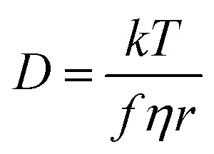
The transport properties of ILs arise from a number of important factors on the molecular level, including size, shape, mass, degree of fluorination and ion conformational flexibility.22 There are well established connections between molecular quantities and transport properties, such as those given by the classical Stokes–Einstein–Sutherland relation, eqn (1).23
 |
1 |
Here, the diffusion coefficient D of a solute in a fluid is determined by the viscosity η of the fluid and the hydrodynamic radius r of the solute, k is the Boltzmann constant, and T is the temperature. The factor f based on Stokes' law is usually chosen between 6π (stick conditions where solvent molecules adhere to a boundary) or 4π (slip conditions), with 6π being the prevalent choice for ILs. The classical description of viscosity links with the forces acting between molecules and their velocity and momentum, to which size and mass contribute. The combined impact of these factors is complex. For example, increasing fluorination will reduce interactions between the ions and increase fluidity. However, the increase in size and mass of the ions (relative to H) will also decrease fluidity.24–26 A careful consideration of probe molecules and the underlying assumptions can reveal much about the structure and dynamics of ionic liquids.27 Nevertheless, simple relations such as (1) can also fail due to the formation of heterogeneous domains within an IL.23,28–31
A widely used design element for ILs relies on employing short and flexible alkyl side chains on cations to increase fluidity. Conformational flexibility is the ability of a molecule to exist in two or more structural/atomic arrangements separated by energy barriers low enough to be easily overcome at relevant temperatures. Enhanced conformational flexibility contributes to increased molecular mobility. In addition, the availability of many different conformers increases the entropy of the liquid phase. Thus, flexible ions tend to lead to a decrease in both the viscosity and the melting point of ILs.15,32 For example, the lower viscosity of phosphonium ILs compared to ammonium ILs is in part due to a more facile rotation around the P–C bond.33 It has been established that, if the barrier for the alkyl chain rotation is increased, the dynamics slows down.33–35 Moreover, flexible side chains moving in the region surrounding the positive charge make it kinetically more difficult for anions to approach.36 Alkyl side chains also shield the charged core of IL ions, leading to reduced Coulomb interactions and thus reduced viscosity.36 A caveat is that the alkyl chain must be short enough to be mobile. Long alkyl chains are harder to move (larger mass), and beyond approximately six CH2 units exhibit sufficiently strong van der Waals attractions to form nanoscale lipophilic domains within the IL. Thus, studying alkyl side chain flexibility can be complicated by simultaneous changes to the overall ion–ion intermolecular interactions.16
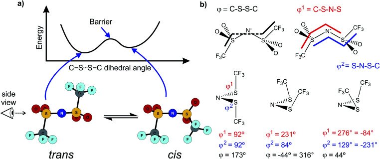
Alkyl side chain flexibility has been extensively studied,22,33,34,36,37 however there are very few investigations of other forms of conformational flexibility, particularly for anions. One set of anions that has been examined is the bis(trifluoromethanesulfonyl)imide [N(Tf)2]− and closely related analogues such as bis(fluorosulfonyl)imide [N(Fs)2]−. Both anions generate ILs which have low viscosities compared to other ILs.38–40 Both [N(Fs)2]− and [N(Tf)2]− anions exist as a mixture of two conformers, typically denoted as cis (cisoid) and trans (transoid), Fig. 1a. Cis and trans are defined through the torsion or dihedral angles of each “arm” (φ1, φ2), Fig. 1b. If the barrier separating the cis and trans conformers is small, fast reorientation of the CF3 groups relative to each other through rotation around the C–S–S–C torsion angle occurs. Using a combination of theory and experiment, a direct connection has been established between the dynamics of cis–trans interconversion and ion transport for several [N(Tf)2]− based ILs.35,41 There are also a few examples of more exotic combinations, such as the mixed (fluorosulfonyl)(trifluoromethanesulfonyl)imide [N(Fs)(Tf)]− anion.42
Fig. 1. (a) 1D potential energy surface showing the cis and trans minima and barrier for interconversion for [N(Tf)2]−. The eye indicates the perspective used in the projection in Fig. 2. (b) Minimum geometries for [N(Tf)2]− and the choice of dihedral angles.
ILs can be formed with a very wide range of anions and tuning the anion chemical structure offers a way to control the properties of the resulting IL. Viscosity can be reduced by employing “non-interacting” anions such as [BF4]− and [PF6]−. However, another route into reducing IL viscosity can be accessed through understanding conformer flexibility (in larger anions).
[N(Tf)2]− has played a central role in the development of low melting point, low viscosity ILs.43 [N(Tf)2]− salts are readily available (due to the use of Li[N(Tf)2] in battery technology), and the thermal, chemical and electrochemical stability of [N(Tf)2]− is well documented.13,44,45 New cations are often first tested with [N(Tf)2]− due to a predictable formation of low melting point ILs. New anions are often compared against [N(Tf)2]−, which provides a common reference for the IL community. Moreover, chemical analogues of [N(Tf)2]− can be easily envisaged. The [N(Tf)2]− anion is thus a logical starting point for a systematic study of anion conformational flexibility, not only to produce new ionic liquids, but also to better understand those that already exist.
While the cis–trans barrier height is typically the primary focus, equally important is the relative energy of the two conformers which determines the relative concentration of each conformer. If one of the conformers is not populated at room temperature, then this conformer will only have a marginal influence on the physical properties of the liquid. The energy difference and relative concentration of the two conformers of [N(Tf)2]− has been investigated for several ILs. In most cases, the trans conformer is found to be more stable by 3 to 5 kJ mol−1.46–49 However, the cis conformation is entropically favoured, as there are twice as many symmetrically equivalent structures compared to the trans conformer.37 Thus, an approximately equimolar mixture of cis and trans structures is found at room temperature.35,37,40,47
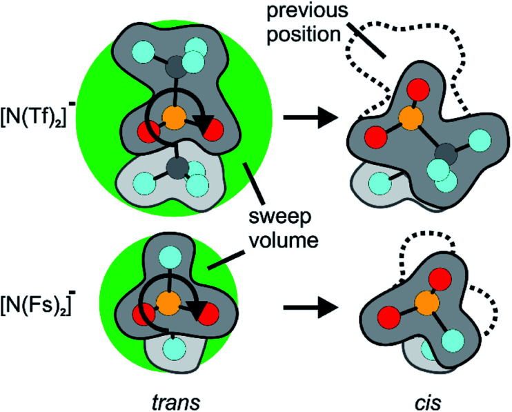
Similar findings have been reported for [N(Fs)2]−, which also exists as a mixture of cis and trans conformers.40,50 However, ILs based on [N(Fs)2]− do not show a pronounced correlation between the barrier height of cis–trans interconversion and ion transport.35 Thus, in contrast to ILs with the [N(Tf)2]− anion, conformational relaxation is not the dominant mechanism for translational relaxation. This difference between [N(Tf)2]− and [N(Fs)2]− based ILs can be explained by the larger size of the CF3 groups in [N(Tf)2]− (i.e. N(SO2CF3)2−) compared to the fluorine atoms in [N(Fs)2]− (i.e. N(SO2F)2−), Fig. 2.41 The fluorine end group in [N(Fs)2]− is comparable in size to the oxygen atoms of the sulfonyl group, whereas the CF3 groups in [N(Tf)2]− take up a larger volume. Rotation around the N–S bonds does not change the shape of the molecule significantly for [N(Fs)2]−. The CF3 groups increase the steric hindrance, for example, the C–S–S–C angle in cis-[N(Tf)2]− is twice that of the F–S–S–F angle in cis-[N(Fs)2]−.50 In addition, the bulky CF3 groups in [N(Tf)2]− increase the sweep volume; the volume required for the trans to cis rotation, Fig. 2.
Fig. 2. Reorientation of the CF3 group in [N(Tf)2]− compared to the much smaller volume for F in [N(Fs)2]−. The sweep volume is represented by the bright green circles.
A flexible anion such as [N(Tf)2]− samples many different conformations, and is entropically favoured. The rotational motion of the bulky CF3 group also leads to the creation of voids, i.e. free volume. The voids can be dynamically occupied by a solute or another solvent molecule. Thus, conformational flexibility facilitates translational motion within the IL, leading to increased diffusion and fluidity.25,51 The correlation between conformational reorganisation of bulky groups and ion transport is evidenced by the higher activation volume for diffusion of [N(Tf)2]− compared to [N(Fs)2]−.41 The free volume in ILs with highly flexible ions such as [N(Tf)2]− can also increase the solubility of gases, which is an important aspect for practical applications such as CO2 capture.52
In this paper we predict how conformational flexibility can be tuned to obtain optimum transport properties. A detailed examination is made of the [N(Tf)2]−cis–trans potential energy surface (PES) establishing a robust methodology. The method is then extended to analyse chemically modified analogues of [N(Tf)2]− in order to obtain a range of anions with different conformational properties. From this range, anions can then be selected as the basis for ILs for further experimental or theoretical investigation. Understanding how the [N(Tf)2]− or [N(Fs)2]− anions produce a high fluidity, delivers information that can be applied more generally to other IL anions. Circumventing the use of highly fluorinated anions that are expensive and environmentally damaging to produce is highly desirable.53,54 Routes to high flexibility, other than through fluorination, are described. Moreover, the insights obtained can be used to design novel ILs with high molar conductivity, fluidity and ion mobility. High fluidity ILs are of significant interest for any application that relies on fast diffusion, for example, battery and supercapacitor technologies.
Materials and methods
Syntheses
Syntheses were performed using standard Schlenk conditions. Starting material TfNH2 was obtained from Fluorochem in 99% purity, MsNH2 was obtained from TCI in >98% purity, and both used as received. The syntheses of the free acids uses an improved literature procedure via acidic catalysis.55 NMR for the precursors and neat IL show no evidence of impurities, NMR spectra are provided in the ESI, Sections 10 and 11.† The drying procedures led to an IL water content of less than 100 ppm determined by Karl-Fischer titration. The absence of halides after the metathesis has been confirmed by testing with aqueous silver nitrate solution. This approach is comparable in sensitivity to ion exchange chromatography. Due to the extremely low solubility of silver chloride; a negative silver nitrate test corresponds to a chloride content below ≈10 ppm.56
N-((Trifluoromethyl)sulfonyl)acetamide [H][N(Tf)(Ac)]
25.3 g trifluoromethanesulfonamide (170 mmol, 1.00 eq.) was dissolved in 250 mL acetonitrile. To the homogeneous solution 50 mL acetic anhydride (54 g, 529 mmol, 3.11 eq.) and 300 μL concentrated sulfuric acid (0.55 g/5.60 mmol/3 mol%) was added. The reaction mixture was heated to 60 °C for 3 h and then allowed to cool to room temperature overnight while stirring. The solvent was removed under reduced pressure, and the residue dissolved in 150 mL water together with 20 mL brine. The aqueous solution was continuously extracted with methylene chloride over 3 days using a Kutscher–Steudel extractor. The methylene chloride was then removed under reduced pressure. 300 mL toluene was added to the residue, and the mixture cooled to 4 °C overnight. The toluene was decanted carefully and replaced by 300 mL of fresh toluene, repeating the procedure. The raw product was sublimed in high vacuum with a bath temperature of 30 °C, using a cold finger cooled with dry ice. 8.16 g of the title compound (43 mmol/25% yield) were obtained as colourless solid. Sublimation should be slow and at or below 30 °C, to avoid co-sublimation of trifluoromethanesulfonamide, the absence of which was confirmed by 19F and 13C NMR.
1H NMR (CD3CN, 400 MHz, δ in ppm): 9.93 (br s, 1H, NH), 2.16 (s, 3H, COCH3).
13C{1H} NMR (CD3CN, 100 MHz, δ in ppm): 168.64 (s, COCH3), 120.27 (q, 1JC/F = 320.7 Hz, CF3), 24.47 (s, COCH3).
19F{1H} NMR (CD3CN, 377 MHz, δ in ppm): −77.78 (s, SO2CF3).
HRMS, ESI−: m/z found 189.9792, calc. 189.9786 (M − H)−.
Sodium acetyl(trifluoromethylsulfonyl)imide [Na][N(Tf)(Ac)]
5.80 g N-((trifluoromethyl)sulfonyl)acetamide (30.4 mmol/1.00 eq.) was dissolved at 0 °C in 25 mL of water. This solution was slowly neutralised with 2.58 g sodium bicarbonate (30.7 mmol/1.01 eq.). The resulting homogeneous solution was frozen in liquid nitrogen and allowed to thaw under high vacuum. The resulting solid was dried under high vacuum to constant mass, giving 6.51 g of the title compound (30.6 mmol/quantitative yield) as a colourless solid.
1H NMR (CD3CN, 400 MHz, δ in ppm): 1.91 (s, COCH3).
13C{1H} NMR (CD3CN, 100 MHz, δ in ppm): 180.84 (s, COCH3), 121.63 (q, 1JC/F = 322.6 Hz, CF3), 27.42 (s, COCH3).
19F{1H} NMR (CD3CN, 377 MHz, δ in ppm): −79.98 (s, SO2CF3).
1-Butyl-3-methylimidazolium acetyl(trifluoromethylsulfonyl)imide [C4C1im][N(Tf)(Ac)]
4.55 g 1-butyl-3-methylimidazolium chloride (26.0 mmol/1.00 eq.), 6.47 g NaN(Tf)(Ac) (30.4 mmol/1.17 eq.), 250 mL methylene chloride, and 20 mL water were stirred together for 1 h. The organic phase was separated and washed three times each with 20 mL water. No halide was found when testing the last washing water with aqueous silver nitrate solution. The organic phase was dried over 4 Å molecular sieves and stirred over charcoal for 1 h. The solvent was removed under reduced pressure and the residue dried in high vacuum while stirring at 40 °C for several days up to a week, giving 4.01 g of the title compound (12.2 mmol/47% isolated yield) as colourless liquid.
1H NMR (DMSO-d6 capillary, 400 MHz, δ in ppm): 8.74 (s, 1H, NCHN), 7.27 (s, 1H, CH2NCHCHN), 7.17 (s, 1H, NCHCHNCH3), 3.75 (t, 3JH/H = 7.4 Hz, 2H, NCH2), 3.48 (s, 3H, NCH3), 1.41 (s, 3H, COCH3), 1.33 (p, 3JH/H = 7.4 Hz, 2H, CH2CH2CH3), 0.79 (h, 3JH/H = 7.1 Hz, 2H, CH2CH3), 0.36 (t, 3JH/H = 7.4 Hz, 3H, CH2CH3).
13C{1H} NMR (DMSO-d6 capillary, 101 MHz, δ in ppm): 176.56 (s, COCH3), 136.33 (s, NCHN), 122.65 (s, NCHCHNCH3), 121.41 (s, CH2NCHCHN), 119.98 (q, 1JC/F = 324.7 Hz, SO2CF3), 48.11 (s, NCH2), 34.60 (s, NCH3), 30.93 (s, CH2CH2CH3), 25.50 (s, COCH3), 18.08 (s, CH2CH3), 11.79 (s, CH2CH3).
19F{1H} NMR (DMSO-d6 capillary, 377 MHz, δ in ppm): −79.13 (s, SO2CF3).
HRMS, ESI+: m/z found 139.1236, calc. 139.1235 (C4C1im)+.
HRMS, ESI−: m/z found 189.9791, calc. 189.9786 (N(Tf)(Ac))−.
2,2,2-Trifluoro-N-(methanesulfonyl)acetamide [H][N(Ms)(TFA)]
10.1 g methanesulfonamide (106 mmol/1.00 eq.) was dissolved in 100 mL acetonitrile. To the homogeneous solution was added 47.6 g trifluoroacetic anhydride (227 mmol/2.14 eq.) and 180 μL concentrated sulfuric acid (0.33 g/3.36 mmol/3 mol%). The reaction mixture was stirred at room temperature for 4 days. Subsequently, the solvent was removed at reduced pressure without heating over 20 °C. The residue was washed twice with toluene and twice with pentane, allowing the mixture to stand at 4 °C overnight before decanting the solvent. Excess acetic anhydride and acetic acid can inhibit the crystallisation in the first washing steps, in which case the toluene mixture was cooled with dry ice, the toluene decanted from the frozen residue, and the process repeated until crystallisation occurred at 4 °C. The residue was sublimed in high vacuum with a bath temperature of 50 °C, using a cold finger cooled with dry ice. 17.3 g of the title compound (90.6 mmol/85% yield) was obtained as a colourless solid. Sublimation should be slow and at or below 50 °C to avoid co-sublimation of methanesulfonamide, the absence of which was confirmed by 1H and 13C NMR.
1H NMR (CD3CN, 400 MHz, δ in ppm): 10.42 (br s, 1H, NH), 3.32 (s, 3H, SO2CH3).
13C{1H} NMR (CD3CN, 100 MHz, δ in ppm): 156.76 (q, 2JC/F = 41.1 Hz, COCF3), 115.75 (q, 1JC/F = 287.8 Hz, COCF3), 42.04 (s, SO2CH3).
19F{1H} NMR (CD3CN, 377 MHz, δ in ppm): −76.29 (s, COCF3).
HRMS, ESI−: m/z found 189.9791, calc. 189.9786 (M − H)−.
Sodium (methanesulfonyl)(2,2,2-trifluoroacetyl)imide [Na][N(Ms)(TFA)]
7.56 g 2,2,2-trifluoro-N-(methylsulfonyl)acetamide (39.6 mmol/1.00 eq.) was dissolved at 0 °C in 25 mL of water. The solution was slowly neutralised with 3.32 g sodium bicarbonate (39.5 mmol/1.00 eq.). The resulting homogeneous solution was frozen in liquid nitrogen and allowed to thaw under high vacuum. The resulting solid was dried under high vacuum to constant mass, giving 8.5 g of the title compound (39.8 mmol/quantitative yield) as a colourless solid.
1H NMR (D2O, 400 MHz, δ in ppm): 3.14 (s, SO2CH3).
13C{1H} NMR (D2O, 100 MHz, δ in ppm): 163.98 (q, 2JC/F = 36.1 Hz, COCF3), 116.68 (q, 1JC/F = 287.2 Hz, COCF3), 39.45 (s, SO2CH3).
19F{1H} NMR (D2O, 377 MHz, δ in ppm): −75.66 (s, COCF3).
1-Butyl-3-methylimidazolium (methylsulfonyl)(2,2,2-trifluoroacetyl)imide [C4C1im][N(Ms)(TFA)]
5.76 g 1-butyl-3-methylimidazolium chloride (33.0 mmol/1.00 eq.), 8.5 g NaN(Ms)(TFA) (39.8 mmol/1.21 eq.), 250 mL methylene chloride, and 20 mL water were stirred together for 1 h. The organic phase was separated and washed three times with each 20 mL water. No halide was found when testing the last washing water with aqueous silver nitrate solution. The organic phase was dried over molecular sieves 4 Å, and the solvent was removed under reduced pressure. Drying the residue in high vacuum while stirring at 40 °C for several days up to a week gave 4.11 g of the title compound (12.5 mmol/46% isolated yield) as colourless liquid.
1H NMR (DMSO-d6 capillary, 400 MHz, δ in ppm): 8.69 (s, 1H, NCHN), 7.27 (s, 1H, CH2NCHCHN), 7.19 (s, 1H, NCHCHNCH3), 3.76 (t, 3JH/H = 7.0 Hz, 2H, NCH2), 3.47 (s, 3H, NCH3), 2.48 (s, 3H, SO2CH3), 1.31 (p, 3JH/H = 7.1 Hz, 2H, CH2CH2CH3), 0.76 (h, 3JH/H = 7.3 Hz, 2H, CH2CH3), 0.33 (t, 3JH/H = 7.3 Hz, 3H, CH2CH3).
13C{1H} NMR (DMSO-d6 capillary, 101 MHz, δ in ppm):
160.84 (q, 2JC/F = 33.5 Hz, COCF3), 136.11 (s, NCHN), 122.74 (s, NCHCHNCH3), 121.49 (s, CH2NCHCHN), 116.66 (q, 1JC/F = 289.8 Hz, COCF3), 48.07 (s, NCH2), 38.85 (s, SO2CH3), 34.70 (s, NCH3), 30.88 (s, CH2CH2CH3), 18.01 (s, CH2CH3), 11.80 (s, CH2CH3).
19F{1H} NMR (DMSO-d6 capillary, 377 MHz, δ in ppm): −76.08 (s, SO2CF3).
HRMS, ESI+: m/z found 139.1229, calc. 139.1235 (C4C1im)+.
HRMS, ESI−: m/z found 189.9788, calc. 189.9786 (N(Ms)(TFA))−.
Physicochemical measurements
Pulsed field gradient stimulated echo NMR spectra for the determination of self-diffusion coefficients were recorded for the pure substance with an external DMSO-d6 capillary on a BRUKER AVANCE III HD 500 spectrometer with 5 mm BBO SmartProbe at 297 K. The pulse sequence developed by D. Wu et al.57 with bipolar pulsed field gradients, longitudinal eddy current delay of 5 ms,57,58 and spoiler gradients with 1 ms duration was used (ledbpgp2s in the BRUKER library). From this experiment, the self-diffusion coefficients D are obtained using the Stejskal–Tanner eqn (2).58–60
 |
2 |
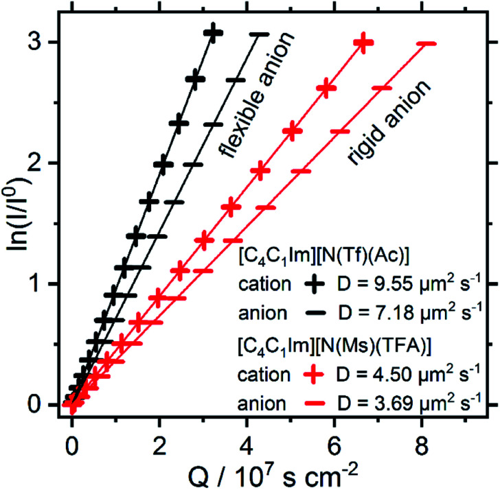
Here, I/I0 is the attenuation of the NMR signal with increasing magnetic field strength g, γ is the gyromagnetic ratio of the observed nucleus, δ is the duration of the gradient pulse (the sum of the duration of the two magnetic field gradient pulses of opposite polarity), Δ the diffusion waiting time, and τ the time between the two bipolar pulses. The relaxation delay was set to 7 times the spin-lattice relaxation time T1, which was determined in an inversion recovery experiment. The duration of the 90° pulse was determined for every sample. 16 linearly spaced magnetic field gradient strengths from 2% to 95% of the maximum magnetic field gradient were used. For each magnetic field gradient, 16 scans were recorded, preceded by 4 dummy scans. The highest magnetic field gradient strength applied during the experiment was 41.271 gauss per cm with a smoothed square gradient pulse shape (SMSQ10.100). The spinner was turned off during the experiment, and the gas flow set to 535 L h−1. Diffusion coefficients can be calibrated against water, a correction value close to 1 means that the effective gradient in the experiment was close to the requested one. In our experimental setup, using water as calibrant, we obtain a gradient correction factor of 1.020. To correct for the deviation, the diffusion coefficients in Fig. 15 can be multiplied by 0.96. However, the deviation is small and within experimental error.
Fig. 15. Steijskal–Tanner plot and self-diffusion coefficients at 297 K of the ILs studied in this work. The experimental uncertainty in the diffusion values is 4% of the absolute value. The reported values are for the nominal gradient strength of the experimental setup.
Dynamic viscosity was determined on a Physica MCR 501 Rheometer (Anton Paar, Graz, Austria) using a cone-plate setup with CP50-1 cone with 49.94 mm diameter and 1.008° cone angle. Prior to the measurements, the samples were dried in high vacuum overnight. The sample temperature was controlled by an H-PTD20H Peltier temperature control equipped with a hood for dry air flow to prevent uptake from ambient water. After temperature equilibration of the sample the shear-dependent viscosity was measured with applied shear rates from 20 to 100 s−1 in linear steps taking 30 points per measurement with 10 seconds time per shear rate. Maximum temperature deviation during the measurement was ±0.003 °C. Since there were no time and shear-rate dependent effects observable, the obtained viscosity values per temperature were averaged. For the temperature dependent viscosity this general procedure was applied from 25 to 105 °C in 5 °C steps. The assumed uncertainty for the viscosity values is about ±2% as estimated by measuring commercial viscosity standards.
Thermal transitions have been determined as described previously.61
Computational details
Calculations have been performed using the Gaussian 09 software package, revision D.01.62 For all calculations, no symmetry was applied.
To benchmark the geometry, full optimisations for all five stationary points of the [N(Tf)2]− anion were carried out at the MP2/6-311+G(d,p), MP2-cc-pVDZ, MP2-aug-cc-pVDZ, MP2-cc-pVTZ, MP2=full/cc-pVTZ, M052X/6-311+G(d,p),63 M06/6-311+G(d,p),64 RB3LYP-GD3BJ/6-311+G(d,p), ω-B97XD/6-311+G(d,p),65 B2PLYPD3/6-311+G(d,p),66 B2PLYP/6-311+G(d,p),67 RB3LYP/6-311+G(d,p), RB3LYP-GD3BJ/6-311+G(d,p) using the SMD parameters for [C4C1im][N(Tf)2],68 M06-GD3/6-311+G(d,p), RHF/6-311+G(d,p), M06/aug-cc-pVTZ, M06/aug-cc-pVDZ, RB3LYP-GD3BJ/6-311G(d,p) and RB3LYP-GD3BJ/6-31+G(d,p) levels of theory, employing a convergence criterion of 10−9 on the density matrix and 10−7 on the energy. Only the two minima (cis and trans) were optimised for RCCSD/cc-pVDZ. Minima and first order saddle points were located and confirmed as such by frequency analysis which confirmed no imaginary or a single imaginary normal mode respectively. Frequency calculations employed a tightened convergence criterion of 10−11 on the density matrix and 10−9 on the energy.
For the energy benchmark calculations, the following levels of theory were used for all five stationary points: MP2/6-311+G(d,p), MP2/cc-pVDZ, MP2/aug-cc-pVDZ, MP2/cc-pVTZ, MP2=full/cc-pVTZ, M052X/6-311+G(d,p), M06/6-311+G(d,p), RB3LYP-GD3BJ/6-311+G(d,p), ω-B97XD/6-311+G(d,p), B2PLYPD3/6-311+G(d,p), B2PLYP/6-311+G(d,p), RB3LYP/6-311+G(d,p), MP2/cc-pVTZ//RB3LYP-GD3BJ/6-311+G(d,p), MP2/cc-pVTZ//M06/6-311+G(d,p), RB3LYP-GD3BJ/6-311+G(d,p) with SMD, M06-GD3/6-311+G(d,p), RHF/6-311+G(d,p), M06/aug-cc-pVTZ, M06/aug-cc-pVDZ, MP2/cc-pVTZ//M06/aug-cc-pVTZ, RB3LYP-GD3BJ/6-311G(d,p), RB3LYP-GD3BJ/6-31+G(d,p) and MP2=full/cc-pVTZ//RB3LYP-GD3BJ/6-311+G(d,p). RCCSD/cc-pVDZ, RCCSD/cc-pVTZ//RCCSD/cc-pVDZ, RCCSD(T)/cc-pVTZ//RCCSD/cc-pVDZ, RCCSD(T)/cc-pVDZ//RCCSD/cc-pVDZ were only used to calculate the energy of the two minima, cis and trans. These energy calculations employed a convergence criterion of 10−9 on the density matrix and 10−7 on the energy.
For the PESs, optimised scans were carried out at the B3LYP-GD3BJ/6-311+G(d,p) level of theory, where GD3BJ stands for Grimme's D3 dispersion correction69 with Becke–Johnson damping.70 All coordinates were optimised except for the two backbone dihedrals which were scanned. For each system, the two dihedrals were scanned from 0 to 360 degrees in steps of 10 degrees, except for [N(Tf)2]−, [CH(Tf)2]−, [N(Tf)(TFA)]− and [N(Fs)2]−, which were scanned in steps of 5 degrees. Subsequently a single point energy calculation was performed at the MP2/cc-pVTZ level of theory (on the B3LYP-GD3BJ/6-311+G(d,p) optimised structure) for every optimised scan structure (i.e. not just the minima). Overall, this required 50 000 MP2 level computations.
From the PES, initial guess structures for stationary points (minima and transition states) were selected and fully optimised (without constraining the backbone dihedral angles) at the B3LYP-GD3BJ/6-311+G(d,p) level of theory. Subsequently, a MP2(full)/cc-pVTZ single point calculation was performed for every converged structure.
Results and discussion
Deriving design elements from theoretical methods
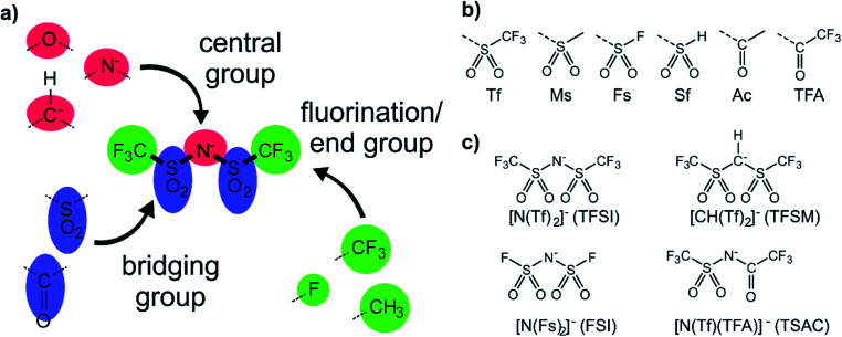
The anions examined in this work are centred around isoelectronic chemical modification of the [N(Tf)2]− anion, Fig. 3a. The central group is either imide (R2N−), methanide (R2CH−) or divalent oxygen (R2O) (red in Fig. 3a). Employing divalent oxygen in the central position allows uncharged systems to be considered. A central design aspect of ILs is delocalisation of charge over a conjugated system.71,72 To this end, bridging groups are preferably carbonyl or sulfonyl (blue in Fig. 3a). Combining charge delocalisation with an electron withdrawing end group allows for further stabilization of the charge. Fluorine as the most electronegative element is often employed, as are fluorinated side chains (green in Fig. 3a). For example, when replacing methyl with trifluoromethyl, the beneficial influence of the fluorination usually compensates for the higher mass of the ions.26,38 The design components central, bridging and end groups are used here to create a set of a priori designed anions, which are interrogated both computationally and experimentally. The nomenclature for the full set of “[N(Tf)2]−a priori analogues” examined here is given in Fig. 3b. A small number of the proposed anions are already known, Fig. 3c. For example, [N(Tf)(TFA)]− has been shown to yield ILs with low viscosities and melting points,73 and [CH(Tf)2]− has been investigated as an intermediate to [C(Tf)3]−,74,75 but rarely as an anion in ILs.76
Fig. 3. (a) Building blocks used in the design of new anions (b) nomenclature of combinations of bridging group and end group (c) combinations of central group, bridging group and end group that yield well-known anions.
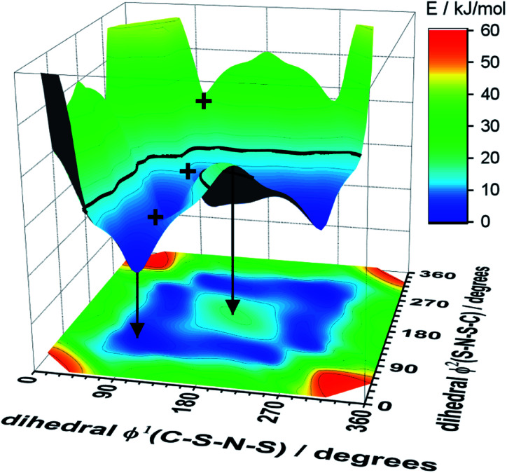
A powerful tool for the investigation of conformational flexibility is analysis of the cis–trans transformation PES. The PES is obtained by plotting the energy as a function of the two C–S–N–S dihedral angles, while all other coordinates are optimized. The PES of [N(Tf)2]− is shown in Fig. 4 and can be compared to that of Canongia Lopes et al.37 All the potential energy surfaces computed as part of this work are available in the ESI, Section 9.†
Fig. 4. The upper part of the image is the 3D potential energy surface (PES) of the [N(Tf)2]− anion and the lower surface the 2D projection. Plus symbols mark selected transition states. The arrows indicate how a local minimum and maximum are mapped on the 2D projection. The bold line at 15 kJ mol−1 will facilitate comparison with other surfaces. The lowest energy conformer is taken as zero reference.
The energy difference between the cis and trans conformers of [N(Tf)2]− is small and thus the theoretical investigation is challenging. For the screening of a large number of structures, computationally less expensive methods such as density functional theory (DFT) are often preferable. However in many situations, more accurate PESs are required, for example in MD force field development.77 Moreover, in many studies only the accuracy of minima and not transition states (TS) are examined; TS often include more electron correlation than minima. In these cases, higher levels of theory, such as second-order Møller–Plesset perturbation theory (MP2), are desirable. Dissociation energies obtained at the MP2 level with large basis sets typically have errors in the region of 10 kJ mol−1.78 Extensive studies, such as those required for PES exploration are only feasible for single point MP2 energy evaluations on structures optimised at a lower level. The error associated with changes in correlation energy upon formation or breaking of bonds is difficult to compute, however, correlation effects are less critical for the calculation of relative energies of conformers, where no bonds are broken or formed.79 Smith et al. found (for alkane conformers) energy deviations of less than 1 kJ mol−1 between MP2/cc-pVTZ//MP2/6-311G(2df,p) and high quality coupled cluster calculations.80
To ensure robust computational results, a benchmarking study has been undertaken on the [N(Tf)2]− anion, the results are presented in the ESI, Section 4.† The energies and geometries of five key stationary points for (gas phase) isolated [N(Tf)2]− have been calculated at different levels of theory and compared against a benchmark MP2(full)/cc-pVTZ level computation. For the [N(Tf)2]− PES there are two unique structurally distinct minima, 1 cis and 1 trans conformer, however, due to the symmetry there are twice as many cis conformers on the full PES. There are three unique structures corresponding to transition states (transitions between each cis and the trans conformer, and the transition state connecting the two cis structures). Four criteria are evaluated; the combined root-mean-square deviation (RMSD) of the five barriers, the absolute relative energy of the two cis to trans minima, and the RMSD of the dihedral angles (φ1, φ2) for each stationary point.
The energy difference between cis and trans conformers is well within experimental results  48–50 for all the tested methods, except Hartree–Fock. In general, the RMSD for the energy barriers of the DFT functionals is close to 1 kJ mol−1, in agreement with recent literature.81 The accuracy can be improved by an order of magnitude to ≈0.1 kJ mol−1 using correlated methods (MP2, CCSD(T)) but at substantial cost. For lower computational effort the DFT energy can be significantly improved by performing a single point MP2/cc-pVTZ calculation on the optimised DFT geometry. In this work, MP2/cc-pVTZ//RB3LYP-GD3BJ/6-311+G(d,p) has been selected because the accuracy is within the desired limit and the method allows for comparison with other computations carried out within the group.
The MP2(FC)/cc-pVTZ//M06/6-311+G(d,p) method exhibits a marginally improved performance. Structurally, the widely used B3LYP hybrid functional performed rather poorly, however including dispersion corrections decreased the RMSD of the dihedrals to less than 3°. Further computational detail is available in the Computational methods section.
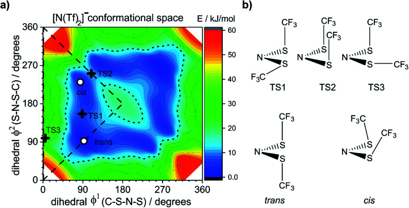
The dihedral 2D-PES for [N(Tf)2]− (MP2/cc-pVTZ//RB3LYP-GD3BJ/6-311+G(d,p)) is presented in Fig. 5a, dark blue represents low energy and red high energy. The PES has two mirror planes, thus the triangular area enclosed by the long dashed lines is sufficient to describe the full PES, all other minima or transition states are symmetrically equivalent. Within the unique “quarter” are 2 minima (circles), one cis and one trans (the global minimum), Fig. 5b. The minima are separated by transition states (crosses). The TS1 and TS3 barriers convert cis–trans, and TS2 separates two cis conformers, Fig. 5b. TS1, TS2 and TS3 have energies of 7, 11 and 24 kJ mol−1, respectively (relative to the global minimum, trans).
Fig. 5. (a) PES of [N(Tf)2]−, (b) stationary point structures (oxygen atoms not shown). Open circles denote minima, black crosses denote transition states. The dotted line is drawn at 15 kJ mol−1 to facilitate comparison with other surfaces. The lowest energy conformer is taken as the zero reference.
Classical molecular dynamics simulations of [N(Tf)2]− sample mostly the blue region, encased by the dotted line drawn at 15 kJ mol−1. TS2 (between the two cis conformers) is crossed much less on a molecular dynamics time scale (hundreds of picoseconds) than TS1.37 In a Boltzmann-distributed system with two levels separated by 15 kJ mol−1, approximately 0.2% of the particles are in the higher energy level. In the following, the 15 kJ mol−1 line will be used as a common reference to compare different PESs.
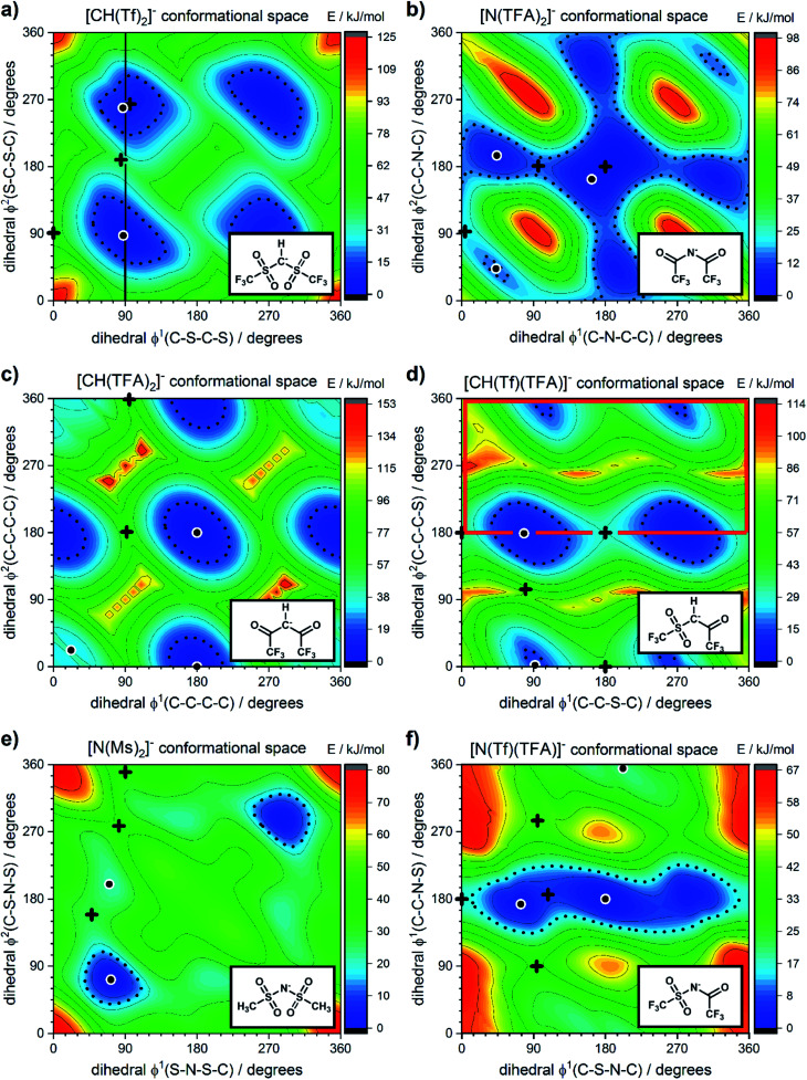
The torsional PESs for the set of a priori [N(Tf)2]− analogues [CH(Tf)2]−, [N(TFA)2]−, [CH(TFA)2]−, [N(Tf)(TFA)]−, [CH(Tf)(TFA)]− and [N(Ms)2]− are presented in Fig. 6. First, how changes in the central group (N) impact on the cis–trans PES will be examined, followed by an examination of the effects of varying the bridging sulfonyl group or RSO2 moiety, and lastly the hydrogenation/fluorination of the substituent CF3 end groups will be considered. The impact of the chemical changes on the energy difference between the cis and trans conformers, and the respective TS barriers is summarized in Table 1. A full table of all stationary points for all anions can be found in the ESI, Section 8.†
Fig. 6. PES of (a) [CH(Tf)2]−, (b) [N(TFA)2]−, (c) [CH(TFA)2]−, (d) [CH(Tf)(TFA)]−, (e) [N(Ms)2]−, and (f) [N(Tf)(TFA)]−. Black circles denote minima, black crosses denote transition states. The dotted line is drawn at 15 kJ mol−1 to facilitate comparison with other surfaces. The vertical black line drawn at 90° in (a) indicates the position of the slice used in Fig. 7, 11 and 12. The area enclosed by the bold red line in (d) is sufficient to describe the PES.
Dihedral angles φ1, φ2 and energies of the stationary points for the anions shown in Fig. 6, [N(Tf)2]−, and O(Tf)2.
| System | φ 1/degrees | φ 2/degrees | E/kJ mol−1 | Type of transition |
|---|---|---|---|---|
| [N(Tf)2]− | 92 | 92 | 0.0 | Minimum (trans) |
| 84 | 231 | 3.5 | Minimum (cis) | |
| 89 | 156 | 7.1 | TS (cis–trans, low) | |
| 109 | 251 | 10.8 | TS (cis–cis) | |
| 99 | 355 | 24.3 | TS (cis–trans, high) | |
| O(Tf)2 | 94 | 94 | 0.0 | Minimum (trans) |
| 98 | 203 | 3.5 | Minimum (cis) | |
| 94 | 151 | 6.8 | TS (cis–trans, low) | |
| 120 | 240 | 11.7 | TS (cis–cis) | |
| 101 | 356 | 27.6 | TS (cis–trans, high) | |
| [CH(Tf)2]− | 87 | 87 | 0.0 | Minimum (trans) |
| 101 | 273 | 7.5 | Minimum (cis) | |
| 96 | 264 | 7.6 | TS (cis–cis) | |
| 84 | 189 | 41.0 | TS (cis–trans, low) | |
| 91 | 359 | 53.0 | TS (cis–trans, high) | |
| [N(TFA)2]− | 180 | 180 | 0.0 | TS |
| 163 | 163 | 0.4 | Minimum (flat) | |
| 44 | 195 | 4.3 | Minimum (tilted once) | |
| 43 | 43 | 13.5 | Minimum (tilted twice) | |
| 96 | 181 | 13.7 | TS | |
| 4 | 93 | 20.1 | TS | |
| [CH(TFA)2]− | 180 | 180 | 0.0 | Minimum (flat) |
| 180 | 0 | 2.8 | Minimum (tilted once) | |
| 22 | 22 | 30.9 | Minimum (tilted twice) | |
| 92 | 181 | 74.3 | TS | |
| 95 | 359 | 83.5 | TS | |
| [CH(Tf)(TFA)]− | 78 | 179 | 0.0 | Minimum |
| 92 | 2 | 11.8 | Minimum | |
| 180 | 180 | 28.4 | TS | |
| 0 | 180 | 34.3 | TS | |
| 180 | 0 | 41.7 | TS | |
| 80 | 104 | 90.9 | TS | |
| [N(Ms)2]− | 72 | 72 | 0.0 | Minimum (trans) |
| 70 | 200 | 22.2 | Minimum (cis) | |
| 48 | 159 | 27.4 | TS (cis–trans, low) | |
| 90 | 350 | 33.7 | TS (cis–trans, high) | |
| 82 | 278 | 39.1 | TS (cis–cis) | |
| [N(Tf)(TFA)]− | 180 | 180 | 0.0 | Minimum (flat) |
| 74 | 173 | 2.3 | Minimum (tilted) | |
| 108 | 186 | 6.9 | TS | |
| 0 | 180 | 15.7 | TS | |
| 202 | 355 | 18.9 | Minimum (tilted) | |
| 94 | 90 | 32.3 | TS | |
| 265 | 75 | 39.0 | TS |
Replacing the central nitrogen atom of the [N(Tf)2]− with a methanide group (CH) forms [CH(Tf)2]− and leads to a PES similar to that of [N(Tf)2]−. However, the cis–trans barrier (41 kJ mol−1) is significantly higher leading to the formation of four separate “wells” Fig. 6a, rather than the continuous “ring” observed for the PES of [N(Tf)2]−, Fig. 5a. Triflic anhydride O(Tf)2 is a neutral analogue and isoelectronic with [N(Tf)2]−. The PES of O(Tf)2 is very similar to that of [N(Tf)2]−, see ESI, Section 9.†
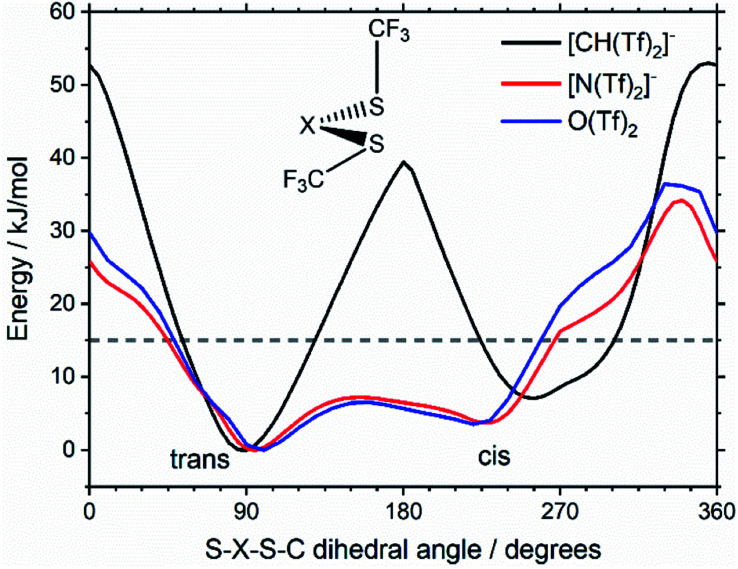
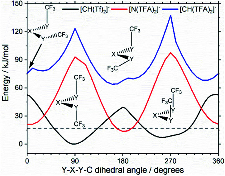
Fig. 7 compares a slice through the cis–trans PES for [N(Tf)2]−, [CH(Tf)2]− and O(Tf)2, where one dihedral angle is fixed at 90° and the other is free to rotate, corresponding to the vertical black line in Fig. 6a. O(Tf)2 and [N(Tf)2]− have minima and barriers that occur at similar geometries and energies. The similarity of the two PESs indicates that the overall −1 charge on [N(Tf)2]− does not significantly affect the cis–trans isomerism. Neutral O(Tf)2 cannot form an IL, but the viscosity of a fluid containing O(Tf)2 could be expected to depend in part on the ease of the cis–trans isomerism. For [CH(Tf)2]− the cis minimum is shifted slightly and the cis–trans barrier is significantly higher in energy. The strong differences between the PES of [CH(Tf)2]− and [N(Tf)2]− indicate that the electronic structure of the central atom is important. Both [CH(Tf)2]− and [N(Tf)2]− are conjugate bases of strong acids,82,83 and thus it can be expected that the [CH(Tf)2]− will be also a weakly coordinating anion in an IL. With both anions being weakly coordinating, the cis–trans isomerism can be expected to play a significant role in differentiating the (dynamic) physical properties of [CH(Tf)2]− and [N(Tf)2]− based ILs.
Fig. 7. Slices through the 3D PES of the PES of [CH(Tf)2]−, [N(Tf)2]−, and O(Tf)2. One of the two S–X–S–C dihedral angles is kept at 90°. The geometry of the lowest lying transition state at ∼180° is shown as inset.
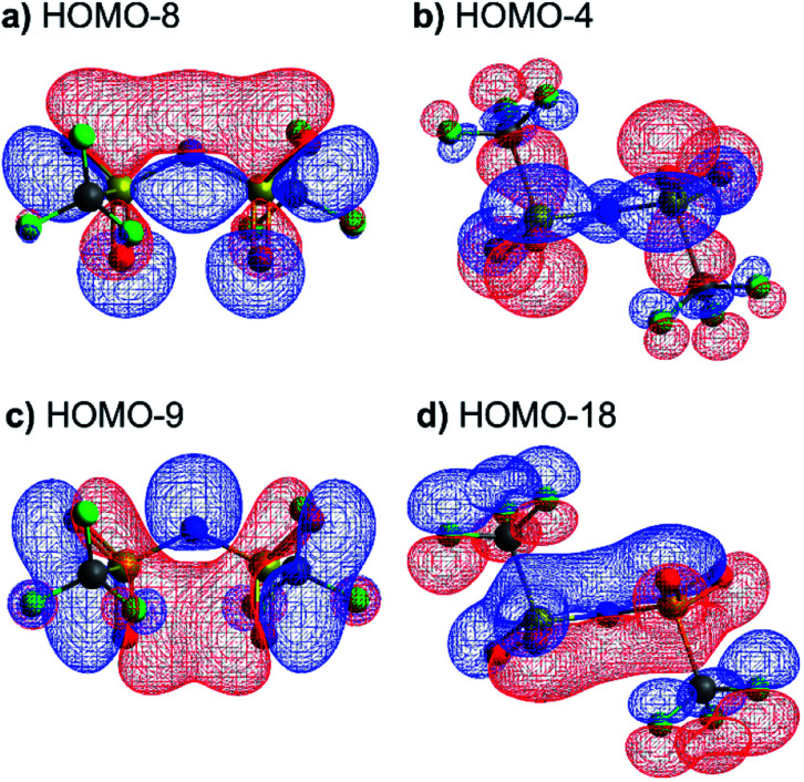
The stability of the cis and trans conformers of [N(Tf)2]−, [CH(Tf)2]− and O(Tf)2 can be attributed to steric and electronic factors. Conceptually, the negative charge of the anion is considered to be more efficiently delocalised over the bridging group when the oxygen atoms are in the S–N–S plane for [N(Tf)2]−. The natural bond orbital (NBO) charge on the N-atom does not change significantly for the trans (−1.195e) vs. the TS (−1.204e) structure. However, extended electronic delocalisation is clearly visible in the molecular orbitals (MOs) of trans [N(Tf)2]−, Fig. 8. Corresponding MOs showing delocalisation are also found for [CH(Tf)2]− and O(Tf)2, see ESI, Section 5.† In terms of a formal Lewis structure, the central nitrogen atom can be considered as sp2 hybridised, however the NBO analysis yields ≈50% s-character for the lone pair in the S–N–S plane (sp hybrid), the lone pair perpendicular to the plane is a pure p-orbital. The valence orbitals on the nitrogen atoms have ≈26% s-character (sp3 hybrid). Both “lone pairs” significantly contribute to bonding molecular orbitals.
Fig. 8. Molecular orbitals showing efficient electronic delocalisation in the trans-[N(Tf)2]− anion.
Using the Arrhenius equation, the relative ratio of the rate constants for cis–trans interconversion can be estimated from the activation energy EA of the cis–trans TS.84 A relative comparison is more reliable than absolute rate values due to a cancellation of errors.79 When the pre-exponential factors are set to be identical, eqn (3) is obtained. Thus, the dynamics of conformational interconversion are predicted to be five orders of magnitude slower for [CH(Tf)2]− compared to [N(Tf)2]−. If the conformational relaxation is coupled to the transport properties as has been hypothesised,35,41 then ILs based on the [CH(Tf)2]− ion should be highly viscous.
 |
3 |
For O(Tf)2, the same analysis shows that the barrier is not changed significantly, with the conversion in [N(Tf)2]− being slower by a factor of 0.9, eqn (4). Due to the similar PES, mixtures of [N(Tf)2]− based ILs with O(Tf)2 could be used to investigate the influence of charge on transport properties.
 |
4 |
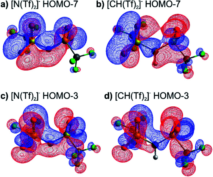
The high barrier for the methanide centre anions can be rationalised with the electronic structure. For [CH(Tf)2]− the in-plane lone pair on the central atom is replaced with a C–H bond, reducing the electronic flexibility of the anion. The reduced electronic flexibility is evidenced in the reduced delocalisation for key (analogous) MOs of [CH(Tf)2]− relative to [N(Tf)2]−, Fig. 9.
Fig. 9. (a) HOMO-7 for [N(Tf)2]−, (b) HOMO-7 for CHTf2, (c) HOMO-3 for [N(Tf)2]−, (d) HOMO-3 for CHTf2. All structures are the lowest energy cis–trans TS.
The RSO2 group has been modified to RCO, and thus this group is denoted as a carboxyl group. Specifically, the triflyl groups of [N(Tf)2]− have been replaced with trifluoroacetyl, TFA, forming the resultant anion [N(TFA)2]−. Alteration of the bridging RSO2 group design element has previously proven successful; ILs based on bis[bis(pentafluoroethyl)phosphinyl]imide [N(PO(C2F5)2)2], were found to have relatively low viscosities, given the mass of the anion.85,86
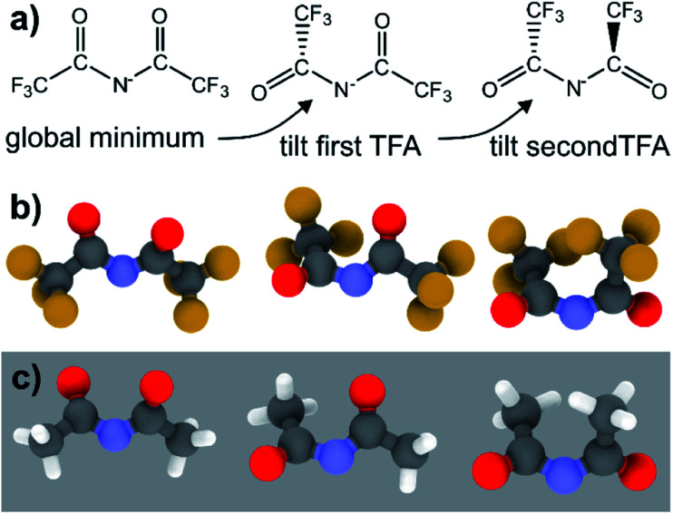
The PES for [N(TFA)2]− is given Fig. 6b and is qualitatively different to that obtained for anions with sulfonyl groups. Comparing the PES of [CH(Tf)2]− and [N(TFA)2]− (Fig. 6a and b) it is noticeable that the surfaces are complementary to each other. A maximum in the PES of one of the surfaces corresponds to a minimum in the other, and vice versa. The global minimum for [N(TFA)2]− is found to be a flat structure with the two dihedrals taking values close to 180°. Additional minima are found with one or both trifluoroacetyl groups being tilted, so that the C–C–N–C dihedrals are close to zero, Fig. 10a and b. The multiple minima described above are very close in energy, Table 1, and thus there are more thermally accessible structures for [N(TFA)2]− compared to [N(Tf)2]− or [CH(Tf)2]−. The cis–trans barrier for [N(TFA)2]− is approximately 7 kJ mol−1 higher than for [N(Tf)2]−, and thus the ratio of rate constants can be estimated as shown in eqn (5).
 |
5 |
Fig. 10. (a) Schematic representation of the conformational changes in [N(TFA)2]−, (b) the optimised minimum geometries of this anion, (c) the corresponding structures for the non-fluorinated analogue [N(Ac)2]−.
The coefficient factor of 0.5 arises because there are twice as many paths leading from the lowest energy conformer of [N(TFA)2]− to one of the tilted structures. Both trifluoroacetyl groups can rotate in both directions (blue central region of the PES), whereas [N(Tf)2]− is limited to the two directions imposed by the circular valley of the PES. Thus, [N(TFA)2]− (compared to [N(Tf)2]−) has more accessible states but also slightly higher barriers. Future molecular dynamics simulations of [N(Tf)2]− compared to [N(TFA)2]− based ILs could offer valuable insight into the impact of the dihedral PES subspace on dynamic transport properties.
The PES for [CH(TFA)2]− (Fig. 6c) qualitatively resembles the PES for [N(TFA)2]− (Fig. 6b), however the minima are much more pronounced (note the different energy scales used in Fig. 6 and the segregated regions enclosed by the 15 kJ mol−1 line for [CH(TFA)2]−). The electronic structure is stabilised through the oxygen atoms taking on a locally planar arrangement and maximising electron delocalisation; for the methanide anions, this effect is more pronounced because only a single lone pair with high p-character is available. The expected minimum with both dihedral angles close to 0° is found for [CH(TFA)2]−, but at a higher energy. The stabilisation of the planar structures leads to the PES for [CH(TFA)2]− being complementary to that of [CH(Tf)2]− (as was found for [N(TFA)2]− compared to [N(Tf)2]−). Minima in the PES (blue region, circles) for the [X(Tf)2]− correspond to maxima in the 2D PES subset (red region) for the [X(TFA)2]− anions, with X being a methanide or imide centre. The complementary minima and maxima can be seen when a slice is taken through the 3D PES, with one dihedral being fixed at 90°, Fig. 11.
Fig. 11. Slices of the PES of [CH(Tf)2]−, [N(TFA)2]−, and [CH(TFA)2]−. One of the two S–X–S–C dihedral angles is kept at 90°. The global minimum of the whole PES is used as the zero value.
When two different bridging groups are incorporated into the anion, as in [CH(Tf)(TFA)]−Fig. 6d, the appropriate PES relevant to each bridging group is observed. The PES is less symmetrical and the red line in Fig. 6d illustrates the unique area within the 2D plot. The trifluoroacetyl group leads to minima at a dihedral angle φ2(C–C–C–S) of 0° (360°) and 180°, whereas the preferred dihedral angles φ1(C–S–C–C) of the triflyl group are at 90° (270°). In contrast, the [N(Tf)(TFA)]− (TSAC) anion, Fig. 6f, prefers a flat structure; the global minimum occurs with both dihedral angles taking values of 180°. Moreover, the tilted conformers are only 2 kJ mol−1 higher in energy and are accessible through a very low barrier of approximately 7 kJ mol−1. Minima exist for both the TFA and the Tf group being tilted, see ESI, Section 6.† However, the minimum with the tilted TFA group is much higher in energy (17 kJ mol−1 higher than the minimum with only the Tf group being tilted). [N(Tf)(TFA)]− is one of the very few asymmetric anion examples that has been experimentally investigated.73 The low viscosity of [N(Tf)(TFA)]− based ILs can be rationalized by the high conformational flexibility of this anion.
Fluorination is one of the most widely used tools in the design of ILs. The introduction of fluorine, often as a perfluorinated alkyl group, can alter the physicochemical properties of an IL.87–89 To better understand the effect of fluorination on conformational flexibility, the PES for pairs of non-fluorinated/fluorinated analogous anions has been explored; [N(Tf)2]−/[N(Ms)2]−, [N(TFA)2]−/[N(Ac)2]−, [CH(TFA)2]−/[CH(Ac)2]−, [CH(Tf)2]−/[CH(Ms)2]−, and [N(Fs)2]−/[N(Sf)2]−, as well as the neutral pairs O(Tf)2/O(Ms)2, O(Fs)2/O(Sf)2 and NH(Tf)2/NH(Ms)2. The non-fluorinated analogue of [N(Tf)2]−, i.e. [N(Ms)2]−, is shown as an example, Fig. 6e, the remaining PESs are presented in the ESI, Section 9.† Compared to [N(Tf)2]−, [N(Ms)2]− has a significantly reduced mass (38%) and a reduced volume due to the shorter van der Waals (vdW) radius of the H atoms, 1.20 Å vs. 1.46 Å,90 leading to ILs with a lower density, moreover, it has also been suggested that [N(Ms)2]− undertakes stronger H-bonding.38 [N(Ms)2]− has a shorter C–C distance (4.57 Å) compared to that in [N(Tf)2]− (5.18 Å). These combined effects (vdW radii, covalent bond distance, H-bonding) are thought to contribute to the large increase in viscosity of ILs employing [N(Ms)2]−.38 For [N(Tf)2]−, the negative charge is shifted to the end groups due to the high electronegativity of fluorine (see the NBO charges in ESI, Section 7†). While non-fluorinated anions are unable to undertake F⋯H–C interactions, there is potential for inter-anion O⋯H–C interactions.38 Nevertheless, the decrease in melting point of ILs composed of [N(Ms)2]− relative to [N(Tf)2]− indicates that the lower mass of the ions has a strong effect on melting. Moreover, nanosegregation into fluorophilic domains can also occur. The structuring effect of fluorinated side chains, such as lamellae formation as probed by small angle X-ray scattering, exceeds the structuring from extended alkyl side chains.91–94
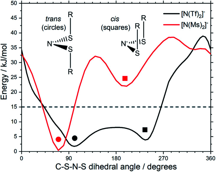
The stability of the cis conformer of [N(Ms)2]− is significantly decreased relative to [N(Tf)2]− and is now 20 kJ mol−1 higher in energy than trans conformer, Fig. 12. Moreover, the trans-to-cis barrier is increased to 27 kJ mol−1, compared to 11 kJ mol−1 for [N(Tf)2]−. Thus, the positions of minima are retained, but their relative energies change. This was observed for the other pairs of fluorinated vs. non-fluorinated systems as well, e.g.Fig. 10b and c. In the systems containing a sulfonyl bridging group, trans structures are favoured over cis structures in the non-fluorinated analogues ([N(Tf)2]−/[N(Ms)2]−, [CH(Tf)2]−/[CH(Ms)2]−, [N(Fs)2]−/[N(Sf)2]−, O(Fs)2/O(Sf)2, NH(Tf)2/NH(Ms)2, and O(Tf)2/O(Ms)2, see ESI, Section 9†). Similarly, in the systems containing a carbonyl bridging group, tilted structures are favoured over flat structures in the non-fluorinated analogues ([N(TFA)2]−/[N(Ac)2]− and [CH(TFA)2]−/[CH(Ac)2]−, see ESI, Section 9†). Thus, on the PES of the non-fluorinated analogues, minima occur at similar geometries, but the energy surface traversed between minima is quantitatively different compared to the fluorinated systems.
Fig. 12. Slices of the PES of [N(Ms)2]− and [N(Tf)2]−. One of the C–S–N–S dihedral angles is kept fixed (90° for [N(Tf)2]−, 80° for [N(Ms)2]−).
Fluorination of anions is known to positively affect the properties of ILs, leading to lower viscosities, higher ionic conductivity, and higher diffusion, provided that the fluorinated groups are not too big.38,72,87–89 It has been demonstrated here that fluorination distinctively affects conformational flexibility, and the properties of ILs with fluorinated anions will also be a function of this flexibility.
Experimental proof of concept
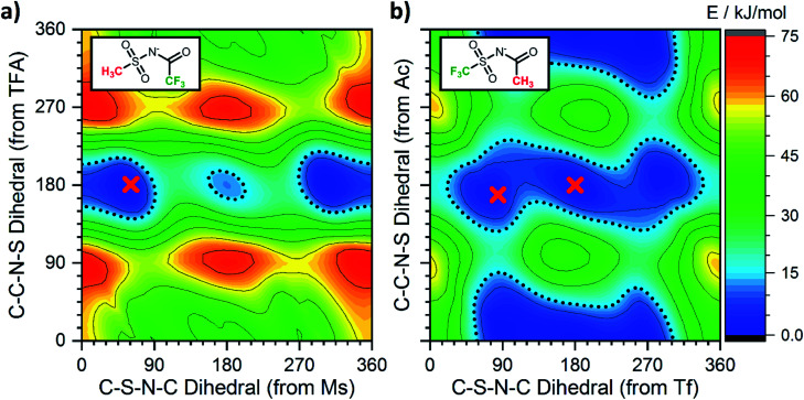
Having employed simpler anions to probe the impact of individual (single) chemical changes, progress can now be made by combining these features in more complex ways. An anion that contributes to a low viscosity IL needs to have multiple minima that are easily accessible over low interconversion barriers. In this respect the PES of [N(TFA)2]− provides a number of low energy minima principally at angles of 180°, however there are still areas of high energy within the PES, primarily near dihedral angles of 0° or 90°. The aim therefore was to vary the anion structure in order to stabilise structures with conformer angles close to 0° (or 90°). [N(Ms)2]− has minima in the trans conformation with both dihedrals close to 90°. Thus [N(Ms)(TFA)]− was constructed and the PES characterised, Fig. 13a. However, the outcome rather than facilitating low minima resulted in over-localisation (as seen for NMs2). Subsequently, the fluorination of the substituents was “reversed” forming [N(Tf)(Ac)]− which delivered the desired PES, Fig. 13b. For [N(Tf)(Ac)]− a flat PES was formed; therefore, multiple conformers can easily interconvert over low barriers.
Fig. 13. Potential energy surfaces of the anions (a) [N(Ms)(TFA)]− and (b) [N(Tf)(Ac)]− in the experimentally investigated ILs. The red crosses correspond to the dihedral angles obtained experimentally from crystal structures of model compounds.
Experimental studies are invaluable in supporting the veracity of an a priori computationally designed anion. However, experimental demonstration of the impact of an individual (single) chemical design change is often significantly challenging, substantially more so than for computational studies. Ideally, the two (or more) ILs characterised must be as similar as is experimentally feasible. In the following, two 1-butyl-3-methylimidazolium [C4C1im]+ based ILs have been synthesised and experimentally characterised employing [N(Ms)(TFA)]− and [N(Tf)(Ac)]− as the IL anion. The rationale behind this choice is verification of the substantially different PESs, Fig. 13, while at the same time using ions with the same mass and degree of fluorination, allowing the influence of conformational flexibility to be directly probed.
Single crystals containing [N(Ms)(TFA)]− or [N(Tf)(Ac)]− with different counter cations were grown and used to determine the solid state structure of the anions by X-ray crystallography. The relevant dihedral angles (φ1, φ2) have been determined from the crystal structures and are indicated by the red crosses in Fig. 13. The experimental crystal structures, Fig. 14, and the structures obtained from ab initio gas phase calculations show excellent agreement. Additional crystal structures and the comparison with theoretical geometries are given in ESI, Section 3.† Even for the crystal structures of the free acids with a bound proton, the geometry is predicted reasonably well by a calculation on an isolated anion, Table 2. Thus, the ab initio PES still dominates the conformation of the anion, even in cases where packing effects and intermolecular interactions are important. The correspondence with anion conformations in bulk ILs can be expected to be even greater, as specific intermolecular interactions are less pronounced.
Fig. 14. ORTEP plots of the crystal structures corresponding to the red crosses in Fig. 13. Structures are (a) [K][N(Tf)(Ac)], (b) [H][N(TFA)(Ms)], and (c) [H][N(Tf)(Ac)]. Thermal ellipsoids at 50% probability. Symmetry codes: (i) −x + 1, y, z; (ii) x + 0.5, y, 1 − z.
Dihedral angles obtained from experimental and theoretical geometries. Full table in ESI, Section 2.
| Crystal structure geometry | Computational geometry | ||||
|---|---|---|---|---|---|
| Sample | φ 1/° | φ 2/° | Model | φ 1/° | φ 2/° |
| [H][N(Tf)(Ac)] | 84 | 169 | [N(Tf)(Ac)]− | 58 | 169 |
| [H][N(Tf)(Ac)] | 84 | 169 | [H][N(Tf)(Ac)] | 78 | 171 |
| [K][N(Tf)(Ac)] | 180 | 180 | [N(Tf)(Ac)]− | 180 | 180 |
| [H][N(TFA)(Ms)] | 181 | 61 | [N(TFA)(Ms)]− | 179 | 50 |
| [H][N(TFA)(Ms)] | 181 | 61 | [H][N(TFA)(Ms)] | 171 | 61 |
Both [N(Ms)(TFA)]− and [N(Tf)(Ac)]− have the same backbone structure and the same degree of fluorination, however as evidenced from the PESs, [N(Ms)(TFA)]− is significantly more restricted to the minimum conformations (rigid anion), and [N(Tf)(Ac)]− is more flexible. These features (of the PES) should lead to increased dynamics for [C4C1im][N(Tf)(Ac)] compared to [C4C1im][N(Ms)(TFA)]. A correlation between translational diffusion and conformational flexibility should be directly visible in the self-diffusion coefficients.41 Pulsed field gradient stimulated echo (PFGSTE) NMR spectroscopy was used to determine the self-diffusion coefficients from the slope of a Steijskal–Tanner plot, Fig. 15.60 In this experiment, the logarithmic attenuation of the NMR signal intensity I is proportional to the collective quantity Q, which is defined in eqn (2) in the Materials and methods section. The slope directly yields the diffusion coefficient. As predicted, the translational mobility is much higher for both the cation and anion in [C4C1im][N(Tf)(Ac)].
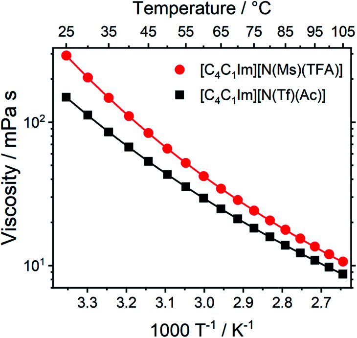
Transport properties, including diffusion, scale with the bulk viscosity. In many cases, high viscosities limit the applicability of ILs. The design concepts in this work enable lower viscosities to be achieved, as demonstrated for [C4C1im][N(Tf)(Ac)] compared to [C4C1im][N(Ms)(TFA)], Fig. 16. The viscosity of the IL with the more rigid anion ([C4C1im][N(Ms)(TFA)], 292 mPa s) is almost twice as high as the viscosity of [C4C1im][N(Tf)(Ac)] (149 mPa s) at room temperature. Experimental data for the viscosity is given in the ESI, Section 3.† The factor by which [C4C1im][N(Ms)(TFA)] is more viscous decreases from 1.96 at 25 °C to 1.22 at 100 °C. Thus, the difference between the viscosities of the two ILs decreases with increasing temperature. This temperature behaviour is a signature of the conformational flexibility, since more conformations become thermally accessible for both anions as the temperature is increased.34,95,96 It is evident that conformational flexibility must be considered when designing ILs, especially for applications near room temperature.
Fig. 16. Viscosity of the two ILs in this work as a function of temperature. Drawn lines are the VFT fits according to eqn (1) in the ESI, Section 3.† The experimental uncertainty in the viscosity values is 2% of the absolute value. The RMSD between experimental viscosities and the VFT fit was found to be 0.090 mPa s.
The increased entropy of the liquid phase for highly flexible ions is known to lower melting points and glass transition temperatures.15 These changes in thermal properties are desirable, as they widen the liquid range for practical applications. The expected effects of conformational flexibility on the thermal transitions are observed for the two ILs in this work. The IL with higher conformational flexibility, i.e. [C4C1im][N(Tf)(Ac)], only showed a glass transition at −78 °C. The glass transition for [C4C1im][N(Ms)(TFA)] (rigid anion) was observed at −63 °C, significantly higher than [C4C1im][N(Tf)(Ac)]. In addition, [C4C1im][N(Ms)(TFA)] demonstrated cold crystallisation at −18 °C and subsequent melting at −8 °C.
In summary the fundamental understanding developed in this work has been employed in the a priori computational design of novel anions. A computational assessment identified two key candidates, one of which has been experimentally proven to exhibit the desired (and advantageous) properties. The increased diffusion and significantly lowered viscosity exhibited by [C4C1im][N(Tf)(Ac)] underlines the importance of considering conformational design equally alongside other design criteria. The insight obtained here can be used more widely to tune the properties of ILs, as for small anions such as [N(Tf)(CN)]−, where only one dihedral is required to describe the conformers.97 The same concept can also help with the preselection of ions from an already available platform, such as the fluorinated aryl sulfonimide tagged anions.98
Conclusions
In this work, three design components that determine the conformational flexibility of [N(Tf)2]− anions and a range of structurally similar a priori analogues have been identified and investigated both computationally and experimentally.
Initially different theoretical methods were evaluated against a data set that considered both minima and transition states of [N(Tf)2]−. Relative to benchmark computations at the MP2(full)/cc-pVTZ level the most accurate energies (≈0.1 kJ mol−1) are obtained at the MP2(FC)/cc-pVTZ//M06/6-311+G(d,p) or MP2(FC)/cc-pVTZ//RB3LYP-GD3BJ/6-311+G(d,p) levels of theory. The 3D PES of [N(Tf)2]− at the MP2(FC)/cc-pVTZ//RB3LYP-GD3BJ/6-311+G(d,p) level for the rotational profile of the two dihedral C–S–N–S angles (φ1, φ2) was presented. Key features such as minima (cis and trans conformers) and transition states (cis–trans and cis–cis) were highlighted and related to the associated 2D torsional PES contour plot.
The corresponding 2D torsional PES contour plots for the [N(Tf)2]− analogues [CH(Tf)2]−, [N(TFA)2]−, [CH(TFA)2]−, [N(Tf)(TFA)]−, [CH(Tf)(TFA)]− and [N(Ms)2]− have been presented. Using the PES contour plots, three design components have been systematically investigated: changes in the central group, varying the bridging group and the end groups. Estimates for the comparative (relative to [N(Tf)2]−) cis–trans interconversion rate have been calculated.
When changing from imide [N(Tf)2]− to methanide [CH(Tf)2]− or neutral O(Tf)2, the potential energy surface minima/maxima remain qualitatively at the same geometries (same C–S–X–S angles φ1, φ2). However, the barriers for cis–trans interconversion of [CH(Tf)2]− are significantly higher, leading to a predicted 9 × 10⁵ decrease in the rate of interconversion. It can be anticipated that the higher barriers will lead to a decrease in ion mobility within an IL.
Variation of the bridging group is the second design concept investigated in this study. Sulfonyl and carbonyl groups were compared. It was observed that the choice of the bridging group qualitatively changes the PES; surfaces were found to be complementary, a maximum in the PES of one of the surfaces corresponds to a minimum in the other, and vice versa. Slightly higher cis–trans barriers were obtained, however greater rotational freedom of the trifluoroacetyl groups leads to more low energy pathways and overall the rates of interconversion were similar for [N(Tf)2]− and [N(TFA)2]−.
Fluorination of the end groups was investigated and identified as a means to shift the relative stability of conformers without changing the ion geometries at the PES minima. For example, it was shown that [N(Tf)2]− has two accessible stable conformations, cis and trans, whereas for [N(Ms)2]− the cis conformers are much higher in energy and thus the trans conformer dominates. This demonstrates that fluorination affects conformational flexibility, which should be taken into account when considering the impact of fluorination on IL properties.
Thus, we have devised a number of design principles for both preferred ion geometries and ion conformational flexibility. By choosing a suitable bridging group it is possible to determine where energy minima will occur on the PES. By changing the central motif, the relative height of TS barriers and depth of stable minima within the PES can be controlled. By employing a selection of alkyl or fluorinated substituents, the preferred lowest energy minimum can be tailored. Overall it is evident that all these features can be predicted by considering delocalisation of the electronic structure.
Based on these principles, the a priori design of the novel anions, [N(Ms)(TFA)]− and [N(Tf)(Ac)]−, was undertaken. These two anions were designed to have significantly different conformational flexibility whilst maintaining similar mass, size, structure, and degree of fluorination. The PESs were computationally characterised and, as expected, [N(Ms)(TFA)]− has fewer thermally accessible areas, while [N(Tf)(Ac)]− has a flat PES where multiple conformers can easily interconvert over low barriers. Hence, the [C4C1im]+ based ILs [C4C1im][N(Tf)(Ac)] and [C4C1im][N(Ms)(TFA)] were synthesised and the self-diffusion coefficients of the ions measured using PFGSTE NMR. Significantly increased diffusion was observed for the more flexible [N(Tf)(Ac)]− compared with the more rigid [N(Ms)(TFA)]− analogue. Furthermore, a pronounced impact on the viscosity was found. The viscosity at room temperature was observed to be twice as high for the IL with the less flexible anion. These experimental results together with the underlying theoretical investigation show that conformational flexibility is a crucial factor to consider when working with ILs.
Overall, we have shown that the approach presented in this work can be used for the in silico engineering of anions tailored for specific applications. Moreover, these conformational design concepts can be easily extended to other chemical systems and building blocks.
Conflicts of interest
There are no conflicts to declare.
Supplementary Material
Acknowledgments
We thank Dr Marlon Jochum, INM-Leibniz Institute for New Materials, for help with the viscosity measurements. We would also like to thank Pete Haycock, Imperial College London, for NMR support, and Lisa Haigh, Imperial College London, for mass spectrometry. This work is funded by the Imperial President's PhD Scholarship. Computational resources provided by the Imperial College Research Computing Service are gratefully acknowledged. DOI: 10.14469/hpc/2232.
Electronic supplementary information (ESI) available: Additional syntheses and crystal growth. X-ray crystallography and comparison with computational geometries. Rheological data and fit parameter. Full results of the benchmark for energy and geometry. Additional molecular orbitals and geometries for key structures of [N(Tf)(TFA)]−. Comparison of NBO charges of [N(Tf)2]− and [N(Ms)2]−. Equilibrium dihedral angles of the backbone, energy, and xyz files for all stationary points of neutral and charged analogues in this work. 2D plots of the potential energy surfaces as well as raw energy data. See DOI: 10.1039/d0sc01379j
References
- Welton T. Biophys. Rev. 2018;10:691–706. doi: 10.1007/s12551-018-0419-2. [DOI] [PMC free article] [PubMed] [Google Scholar]
- Gutowski K. E. Phys. Sci. Rev. 2018;3:1–10. doi: 10.1016/j.revip.2017.11.001. [DOI] [Google Scholar]
- Plechkova N. V. Seddon K. R. Chem. Soc. Rev. 2008;37:123–150. doi: 10.1039/B006677J. [DOI] [PubMed] [Google Scholar]
- Freemantle M. Chem. Eng. News. 1998;76:32–37. doi: 10.1021/cen-v076n013.p032. [DOI] [Google Scholar]
- Niedermeyer H. Ashworth C. Brandt A. Welton T. Hunt P. A. Phys. Chem. Chem. Phys. 2013;15:11566. doi: 10.1039/C3CP50521A. [DOI] [PubMed] [Google Scholar]
- Davis Jr J. H. Chem. Lett. 2004;33:1072–1077. doi: 10.1246/cl.2004.1072. [DOI] [Google Scholar]
- Giernoth R. Angew. Chem., Int. Ed. 2010;49:2834–2839. doi: 10.1002/anie.200905981. [DOI] [PubMed] [Google Scholar]
- Marrucho I. M. Branco L. C. Rebelo L. P. N. Annu. Rev. Chem. Biomol. Eng. 2014;5:527–546. doi: 10.1146/annurev-chembioeng-060713-040024. [DOI] [PubMed] [Google Scholar]
- Cieniecka-Rosłonkiewicz A. Pernak J. Kubis-Feder J. Ramani A. Robertson A. J. Seddon K. R. Green Chem. 2005;7:855. doi: 10.1039/B508499G. [DOI] [Google Scholar]
- Fischer L. Falta T. Koellensperger G. Stojanovic A. Kogelnig D. Galanski M. Krachler R. Keppler B. K. Hann S. Water Res. 2011;45:4601–4614. doi: 10.1016/j.watres.2011.06.011. [DOI] [PubMed] [Google Scholar]
- Billard I. Ouadi A. Gaillard C. Anal. Bioanal. Chem. 2011;400:1555–1566. doi: 10.1007/s00216-010-4478-x. [DOI] [PubMed] [Google Scholar]
- Armand M. Endres F. MacFarlane D. R. Ohno H. Scrosati B. Nat. Mater. 2009;8:621–629. doi: 10.1038/nmat2448. [DOI] [PubMed] [Google Scholar]
- Moreno M. Simonetti E. Appetecchi G. B. Carewska M. Montanino M. Kim G.-T. Loeffler N. Passerini S. J. Electrochem. Soc. 2017;164:A6026–A6031. doi: 10.1149/2.0051701jes. [DOI] [Google Scholar]
- Dong K. Liu X. Dong H. Zhang X. Zhang S. Chem. Rev. 2017;117:6636–6695. doi: 10.1021/acs.chemrev.6b00776. [DOI] [PubMed] [Google Scholar]
- Krossing I. Slattery J. M. Daguenet C. Dyson P. J. Oleinikova A. Weingärtner H. J. Am. Chem. Soc. 2006;128:13427–13434. doi: 10.1021/ja0619612. [DOI] [PubMed] [Google Scholar]
- Hayes R. Warr G. G. Atkin R. Chem. Rev. 2015;115:6357–6426. doi: 10.1021/cr500411q. [DOI] [PubMed] [Google Scholar]
- Araque J. C. Hettige J. J. Margulis C. J. J. Phys. Chem. B. 2015;119:12727–12740. doi: 10.1021/acs.jpcb.5b05506. [DOI] [PubMed] [Google Scholar]
- Canongia Lopes J. N. Pádua A. A. H. Theor. Chem. Acc. 2012;131:1129. [Google Scholar]
- Kirchner B. Hollóczki O. Canongia Lopes J. N. Pádua A. A. H. Wiley Interdiscip. Rev.: Comput. Mol. Sci. 2015;5:202–214. [Google Scholar]
- Izgorodina E. I. Seeger Z. L. Scarborough D. L. A. Tan S. Y. S. Chem. Rev. 2017;117:6696–6754. doi: 10.1021/acs.chemrev.6b00528. [DOI] [PubMed] [Google Scholar]
- Zahn S. Brehm M. Brüssel M. Hollóczki O. Kohagen M. Lehmann S. Malberg F. Pensado A. S. Schöppke M. Weber H. Kirchner B. J. Mol. Liq. 2014;192:71–76. doi: 10.1016/j.molliq.2013.08.015. [DOI] [Google Scholar]
- Tsuzuki S. ChemPhysChem. 2012;13:1664–1670. doi: 10.1002/cphc.201100870. [DOI] [PubMed] [Google Scholar]
- Köddermann T. Ludwig R. Paschek D. ChemPhysChem. 2008;9:1851–1858. doi: 10.1002/cphc.200800102. [DOI] [PubMed] [Google Scholar]
- Abbott A. P. ChemPhysChem. 2005;6:2502–2505. doi: 10.1002/cphc.200500283. [DOI] [PubMed] [Google Scholar]
- Abbott A. P. ChemPhysChem. 2004;5:1242–1246. doi: 10.1002/cphc.200400190. [DOI] [PubMed] [Google Scholar]
- Barthen P. Frank W. Ignatiev N. Ionics. 2015;21:149–159. doi: 10.1007/s11581-014-1153-9. [DOI] [Google Scholar]
- Kaintz A. Baker G. Benesi A. Maroncelli M. J. Phys. Chem. B. 2013;117:11697–11708. doi: 10.1021/jp405393d. [DOI] [PubMed] [Google Scholar]
- Araque J. C. Daly R. P. Margulis C. J. J. Chem. Phys. 2016;144:204504. doi: 10.1063/1.4951012. [DOI] [PubMed] [Google Scholar]
- Berrod Q. Ferdeghini F. Zanotti J.-M. Judeinstein P. Lairez D. García Sakai V. Czakkel O. Fouquet P. Constantin D. Sci. Rep. 2017;7:2241. doi: 10.1038/s41598-017-02396-7. [DOI] [PMC free article] [PubMed] [Google Scholar]
- Araque J. C. Yadav S. K. Shadeck M. Maroncelli M. Margulis C. J. J. Phys. Chem. B. 2015;119:7015–7029. doi: 10.1021/acs.jpcb.5b01093. [DOI] [PubMed] [Google Scholar]
- Taylor A. W. Licence P. Abbott A. P. Phys. Chem. Chem. Phys. 2011;13:10147–10154. doi: 10.1039/C1CP20373H. [DOI] [PubMed] [Google Scholar]
- Qi J. Hu Y. Zhao Y. Li J. Chin. J. Chem. Eng. 2015;23:1565–1571. doi: 10.1016/j.cjche.2015.04.013. [DOI] [Google Scholar]
- Scarbath-Evers L. K. Hunt P. A. Kirchner B. MacFarlane D. R. Zahn S. Phys. Chem. Chem. Phys. 2015;17:20205–20216. doi: 10.1039/C5CP00340G. [DOI] [PubMed] [Google Scholar]
- Tsuzuki S. Matsumoto H. Shinoda W. Mikami M. Phys. Chem. Chem. Phys. 2011;13:5987. doi: 10.1039/C0CP02087G. [DOI] [PubMed] [Google Scholar]
- Borodin O. Gorecki W. Smith G. D. Armand M. J. Phys. Chem. B. 2010;114:6786–6798. doi: 10.1021/jp911950q. [DOI] [PubMed] [Google Scholar]
- Blundell R. K. Licence P. Chem. Commun. 2014;50:12080–12083. doi: 10.1039/C4CC05505E. [DOI] [PubMed] [Google Scholar]
- Canongia Lopes J. N. Shimizu K. Pádua A. A. H. Umebayashi Y. Fukuda S. Fujii K. Ishiguro S. J. Phys. Chem. B. 2008;112:1465–1472. doi: 10.1021/jp076997a. [DOI] [PubMed] [Google Scholar]
- Pringle J. M. Golding J. Baranyai K. Forsyth C. M. Deacon G. B. Scott J. L. MacFarlane D. R. New J. Chem. 2003;27:1504–1510. doi: 10.1039/B304072K. [DOI] [Google Scholar]
- Tokuda H. Hayamizu K. Ishii K. Susan M. A. B. H. Watanabe M. J. Phys. Chem. B. 2004;108:16593–16600. doi: 10.1021/jp047480r. [DOI] [Google Scholar]
- Fujii K. Seki S. Fukuda S. Takamuku T. Kohara S. Kameda Y. Umebayashi Y. Ishiguro S. J. Mol. Liq. 2008;143:64–69. doi: 10.1016/j.molliq.2008.05.011. [DOI] [Google Scholar]
- Suarez S. N. Rúa A. Cuffari D. Pilar K. Hatcher J. L. Ramati S. Wishart J. F. J. Phys. Chem. B. 2015;119:14756–14765. doi: 10.1021/acs.jpcb.5b08658. [DOI] [PMC free article] [PubMed] [Google Scholar]
- Giffin G. A. Laszczynski N. Jeong S. Jeremias S. Passerini S. J. Phys. Chem. C. 2013;117:24206–24212. doi: 10.1021/jp408565b. [DOI] [Google Scholar]
- Bonhôte P. Dias A.-P. Papageorgiou N. Kalyanasundaram K. Grätzel M. Inorg. Chem. 1996;35:1168–1178. doi: 10.1021/ic951325x. [DOI] [PubMed] [Google Scholar]
- Kalhoff J. Eshetu G. G. Bresser D. Passerini S. ChemSusChem. 2015;8:2154–2175. doi: 10.1002/cssc.201500284. [DOI] [PubMed] [Google Scholar]
- Rogers E. I. Šljukić B. Hardacre C. Compton R. G. J. Chem. Eng. Data. 2009;54:2049–2053. doi: 10.1021/je800898z. [DOI] [Google Scholar]
- Martinelli A. Matic A. Johansson P. Jacobsson P. Börjesson L. Fernicola A. Panero S. Scrosati B. Ohno H. J. Raman Spectrosc. 2011;42:522–528. doi: 10.1002/jrs.2713. [DOI] [Google Scholar]
- Umebayashi Y. Mitsugi T. Fujii K. Seki S. Chiba K. Yamamoto H. Canongia Lopes J. N. Pádua A. A. H. Takeuchi M. Kanzaki R. Ishiguro S. J. Phys. Chem. B. 2009;113:4338–4346. doi: 10.1021/jp9009146. [DOI] [PubMed] [Google Scholar]
- Lassègues J. C. Grondin J. Holomb R. Johansson P. J. Raman Spectrosc. 2007;38:551–558. doi: 10.1002/jrs.1680. [DOI] [Google Scholar]
- Fujii K. Fujimori T. Takamuku T. Kanzaki R. Umebayashi Y. Ishiguro S. J. Phys. Chem. B. 2006;110:8179–8183. doi: 10.1021/jp0612477. [DOI] [PubMed] [Google Scholar]
- Fujii K. Seki S. Fukuda S. Kanzaki R. Takamuku T. Umebayashi Y. Ishiguro S. J. Phys. Chem. B. 2007;111:12829–12833. doi: 10.1021/jp074325e. [DOI] [PubMed] [Google Scholar]
- Powell R. E. Roseveare W. E. Eyring H. Ind. Eng. Chem. 1941;33:430–435. doi: 10.1021/ie50376a003. [DOI] [Google Scholar]
- Hu Y.-F. Liu Z.-C. Xu C.-M. Zhang X.-M. Chem. Soc. Rev. 2011;40:3802. doi: 10.1039/C0CS00006J. [DOI] [PubMed] [Google Scholar]
- Muldoon M. J. Aki S. N. V. K. Anderson J. L. Dixon J. K. Brennecke J. F. J. Phys. Chem. B. 2007;111:9001–9009. doi: 10.1021/jp071897q. [DOI] [PubMed] [Google Scholar]
- Sarbu T. Styranec T. J. Beckman E. J. Ind. Eng. Chem. Res. 2000;39:4678–4683. doi: 10.1021/ie0003077. [DOI] [Google Scholar]
- Martin M. T. Roschangar F. Eaddy J. F. Tetrahedron Lett. 2003;44:5461–5463. doi: 10.1016/S0040-4039(03)01324-8. [DOI] [Google Scholar]
- Villagrán C. Deetlefs M. Pitner W. R. Hardacre C. Anal. Chem. 2004;76:2118–2123. doi: 10.1021/ac035157z. [DOI] [PubMed] [Google Scholar]
- Wu D. H. Chen A. D. Johnson C. S. J. Magn. Reson., Ser. A. 1995;115:260–264. doi: 10.1006/jmra.1995.1176. [DOI] [Google Scholar]
- Sørland G. H., Dynamic Pulsed-Field-Gradient NMR, Springer Berlin Heidelberg, Berlin, Heidelberg, 2014, vol. 110 [Google Scholar]
- Johnson C. S. Prog. Nucl. Magn. Reson. Spectrosc. 1999;34:203–256. doi: 10.1016/S0079-6565(99)00003-5. [DOI] [Google Scholar]
- Stejskal E. O. Tanner J. E. J. Chem. Phys. 1965;42:288–292. doi: 10.1063/1.1695690. [DOI] [Google Scholar]
- Philippi F. Rauber D. Zapp J. Präsang C. Scheschkewitz D. Hempelmann R. ChemPhysChem. 2019;20:443–455. doi: 10.1002/cphc.201800939. [DOI] [PubMed] [Google Scholar]
- Frisch M. J., Trucks G. W., Schlegel H. B., Scuseria G. E., Robb M. A., Cheeseman J. R., Scalmani G., Barone V., Mennucci B., Petersson G. A., Nakatsuji H., Caricato M., Li X., Hratchian H. P., Izmaylov A. F., Bloino J., Zheng G., Sonnenberg J. L., Hada M., Ehara M., Toyota K., Fukuda R., Hasegawa J., Ishida M., Nakajima T., Honda Y., Kitao O., Nakai H., Vreven T., Montgomery J. J. A., Peralta J. E., Ogliaro F., Bearpark M., Heyd J. J., Brothers E., Kudin K. N., Staroverov V. N., Kobayashi R., Normand J., Raghavachari K., Rendell A., Burant J. C., Iyengar S. S., Tomasi J., Cossi M., Rega N., Millam J. M., Klene M., Knox J. E., Cross J. B., Bakken V., Adamo C., Jaramillo J., Gomperts R., Stratmann R. E., Yazyev O., Austin A. J., Cammi R., Pomelli C., Ochterski J. W., Martin R. L., Morokuma K., Zakrzewski V. G., Voth G. A., Salvador P., Dannenberg J. J., Dapprich S., Daniels A. D., Farkas Ö., Foresman J. B., Ortiz J. V., Cioslowski J., and Fox D. J., Gaussian 09, Revision D.01, Gaussian, Inc., Wallingford CT, 2009 [Google Scholar]
- Zhao Y. Schultz N. E. Truhlar D. G. J. Chem. Theory Comput. 2006;2:364–382. doi: 10.1021/ct0502763. [DOI] [PubMed] [Google Scholar]
- Zhao Y. Truhlar D. G. Theor. Chem. Acc. 2008;120:215–241. [Google Scholar]
- Chai J.-D. Head-Gordon M. Phys. Chem. Chem. Phys. 2008;10:6615. doi: 10.1039/B810189B. [DOI] [PubMed] [Google Scholar]
- Goerigk L. Grimme S. J. Chem. Theory Comput. 2011;7:291–309. doi: 10.1021/ct100466k. [DOI] [PubMed] [Google Scholar]
- Grimme S. J. Chem. Phys. 2006;124:034108. doi: 10.1063/1.2148954. [DOI] [PubMed] [Google Scholar]
- Bernales V. S. Marenich A. V. Contreras R. Cramer C. J. Truhlar D. G. J. Phys. Chem. B. 2012;116:9122–9129. doi: 10.1021/jp304365v. [DOI] [PubMed] [Google Scholar]
- Grimme S. Antony J. Ehrlich S. Krieg H. J. Chem. Phys. 2010;132:154104. doi: 10.1063/1.3382344. [DOI] [PubMed] [Google Scholar]
- Grimme S. Ehrlich S. Goerigk L. J. Comput. Chem. 2011;32:1456–1465. doi: 10.1002/jcc.21759. [DOI] [PubMed] [Google Scholar]
- Cremer T. Kolbeck C. Lovelock K. R. J. Paape N. Wölfel R. Schulz P. S. Wasserscheid P. Weber H. Thar J. Kirchner B. Maier F. Steinrück H.-P. Chem.–Eur. J. 2010;16:9018–9033. doi: 10.1002/chem.201001032. [DOI] [PubMed] [Google Scholar]
- Ignat’ev N. V. Kucheryna A. Bissky G. Willner H. ACS Symp. Ser. 2007;975:320–334. doi: 10.1021/bk-2007-0975.ch022. [DOI] [Google Scholar]
- Matsumoto H. Kageyama H. Miyazaki Y. Chem. Commun. 2002:1726–1727. doi: 10.1039/B204046H. [DOI] [PubMed] [Google Scholar]
- Turowsky L. Seppelt K. Inorg. Chem. 1988;27:2135–2137. doi: 10.1021/ic00285a025. [DOI] [Google Scholar]
- Waller F. J. Barrett A. G. M. Braddock D. C. Ramprasad D. McKinnell R. M. White A. J. P. Williams D. J. Ducray R. J. Org. Chem. 1999;64:2910–2913. doi: 10.1021/jo9800917. [DOI] [PubMed] [Google Scholar]
- Guo Z. Lue B.-M. Thomasen K. Meyer A. S. Xu X. Green Chem. 2007;9:1362. doi: 10.1039/B709786G. [DOI] [Google Scholar]
- Neumann J. Golub B. Odebrecht L.-M. Ludwig R. Paschek D. J. Chem. Phys. 2018;148:193828. doi: 10.1063/1.5013096. [DOI] [PubMed] [Google Scholar]
- Young D. C., Computational Chemistry, John Wiley & Sons, Inc., New York, USA, 2001 [Google Scholar]
- Jensen F., Introduction to Computational Chemistry, John Wiley & Sons, Inc., West Sussex, 2nd edn, 2007 [Google Scholar]
- Smith G. D. Jaffe R. L. J. Phys. Chem. 1996;100:18718–18724. doi: 10.1021/jp960413f. [DOI] [Google Scholar]
- Li A. Muddana H. S. Gilson M. K. J. Chem. Theory Comput. 2014;10:1563–1575. doi: 10.1021/ct401111c. [DOI] [PMC free article] [PubMed] [Google Scholar]
- Burk P. Koppel I. A. Koppel I. Yagupolskii L. M. Taft R. W. J. Comput. Chem. 1996;17:30–41. doi: 10.1002/(SICI)1096-987X(19960115)17:1<30::AID-JCC3>3.0.CO;2-1. [DOI] [Google Scholar]
- Yanai H. Chem. Pharm. Bull. 2015;63:649–662. doi: 10.1248/cpb.c15-00487. [DOI] [PubMed] [Google Scholar]
- Atkins P. W. and de Paula J., Physical Chemistry, WILEY-VCH, Weinheim, 4th edn, 2006 [Google Scholar]
- Ignat’ev N. V. Finze M. Sprenger J. A. P. Kerpen C. Bernhardt E. Willner H. J. Fluorine Chem. 2015;177:46–54. doi: 10.1016/j.jfluchem.2015.03.007. [DOI] [Google Scholar]
- Bejan D. Ignat'ev N. Willner H. J. Fluorine Chem. 2010;131:325–332. doi: 10.1016/j.jfluchem.2009.11.004. [DOI] [Google Scholar]
- Pereiro A. B. Araújo J. M. M. Martinho S. Alves F. Nunes S. Matias A. Duarte C. M. M. Rebelo L. P. N. Marrucho I. M. ACS Sustainable Chem. Eng. 2013;1:427–439. doi: 10.1021/sc300163n. [DOI] [Google Scholar]
- Xue H. Verma R. Shreeve J. M. J. Fluorine Chem. 2006;127:159–176. doi: 10.1016/j.jfluchem.2005.11.007. [DOI] [Google Scholar]
- Vieira N. S. M. Luís A. Reis P. M. Carvalho P. J. Lopes-da-Silva J. A. Esperança J. M. S. S. Araújo J. M. M. Rebelo L. P. N. Freire M. G. Pereiro A. B. J. Chem. Thermodyn. 2016;97:354–361. doi: 10.1016/j.jct.2016.02.013. [DOI] [PMC free article] [PubMed] [Google Scholar]
- Alvarez S. Dalton Trans. 2013;42:8617. doi: 10.1039/C3DT50599E. [DOI] [PubMed] [Google Scholar]
- Rauber D. Zhang P. Huch V. Kraus T. Hempelmann R. Phys. Chem. Chem. Phys. 2017;19:27251–27258. doi: 10.1039/C7CP04814A. [DOI] [PubMed] [Google Scholar]
- Hollóczki O. Macchiagodena M. Weber H. Thomas M. Brehm M. Stark A. Russina O. Triolo A. Kirchner B. ChemPhysChem. 2015;16:3325–3333. doi: 10.1002/cphc.201500473. [DOI] [PMC free article] [PubMed] [Google Scholar]
- Lo Celso F. Appetecchi G. B. Simonetti E. Zhao M. Castner E. W. Keiderling U. Gontrani L. Triolo A. Russina O. Front. Chem. 2019;7:1–14. doi: 10.3389/fchem.2019.00001. [DOI] [PMC free article] [PubMed] [Google Scholar]
- Lo Celso F. Yoshida Y. Castiglione F. Ferro M. Mele A. Jafta C. J. Triolo A. Russina O. Phys. Chem. Chem. Phys. 2017;19:13101–13110. doi: 10.1039/C7CP01971H. [DOI] [PubMed] [Google Scholar]
- Goldstein M. J. Chem. Phys. 1969;51:3728–3739. doi: 10.1063/1.1672587. [DOI] [Google Scholar]
- Gupta P. K. Kob W. J. Non-Crystalline Solids X. 2019;3:100031. doi: 10.1016/j.nocx.2019.100031. [DOI] [Google Scholar]
- Shaplov A. S. Lozinskaya E. I. Vlasov P. S. Morozova S. M. Antonov D. Y. Aubert P.-H. Armand M. Vygodskii Y. S. Electrochim. Acta. 2015;175:254–260. doi: 10.1016/j.electacta.2015.02.228. [DOI] [Google Scholar]
- Huang M. Feng S. Zhang W. Giordano L. Chen M. Amanchukwu C. V. Anandakathir R. Shao-Horn Y. Johnson J. A. Energy Environ. Sci. 2018;11:1326–1334. doi: 10.1039/C7EE03509H. [DOI] [Google Scholar]
Associated Data
This section collects any data citations, data availability statements, or supplementary materials included in this article.


