

Abstract
Peripheral artery disease (PAD) affects more than 200 million people globally. Minimally-invasive endovascular procedures can provide relief and salvage limbs while reducing injury rates and recovery times. Unfortunately, when a calcified chronic total occlusion is encountered, ~25% of endovascular procedures fail due to the inability to advance a guidewire using the view provided by fluoroscopy. To enable a sub-millimeter, robotically-steerable guidewire to cross these occlusions, a novel single-element, dual-band transducer is developed that provides simultaneous multi-frequency, forward-viewing imaging with high penetration depth and high spatial resolution while requiring only a single electrical connection. The design, fabrication, and acoustic characterization of this device are described, and proof-of-concept imaging is demonstrated in an ex vivo porcine artery after integration with a robotically-steered guidewire. Measured center frequencies of the developed transducer were 16 and 32 MHz, with −6 dB fractional bandwidths of 73% and 23%, respectively. When imaging a 0.2-mm wire target at a depth of 5 mm, measured −6 dB target widths were 0.498 ± 0.02 mm and 0.268 ± 0.01 mm for images formed at 16 MHz and 32 MHz, respectively. Measured SNR values were 33.3 dB and 21.3 dB, respectively. 3D images of the ex vivo artery demonstrate high penetration for visualizing vessel morphology at 16 MHz and ability to resolve small features close to the transducer at 32 MHz. Using images acquired simultaneously at both frequencies as part of an integrated forward-viewing, guidewire-based imaging system, an interventionalist could visualize the best path for advancing the guidewire to improve outcomes for patients with PAD.
Keywords: Interventional Ultrasound, Micromachined transducer, Multi-band imaging, Robotic, Steerable guidewire, Synthetic Aperture
I. Introduction
In the United States, 12% of the population has peripheral artery disease [1], resulting in approximately 550,000 new cases of critical limb ischemia per year [1], [2]. Globally, more than 200 million people have peripheral artery disease [2], with more than 60 million individuals exhibiting claudication or atypical pain [3].
Stenosis occurs in peripheral arteries when atherosclerotic plaque develops on the intimal layer. Additionally, arteries can be further occluded by luminal thrombi, medial calcification, and intimal thickening [4]. When moderately-sized peripheral arteries are blocked, the tissues supplied by these arteries become ischemic. Individuals present with claudication, atypical leg pain, or mobility challenges, and thus require revascularization to improve quality of life and prevent loss of limb. Since more than 100 million people are believed to have claudication or critical limb ischemia [1], millions of interventions are required every year. However, approximately 25% of revascularization procedures fail when heavily calcified chronic total occlusions (CTOs) are present due to inability to reach the targeted region responsible for symptoms [5]. Without forward-viewing imaging, the interventionalist cannot see remaining patent channels or distinguish regions with soft plaque from those with hard calcification in order to advance the guidewire beyond calcified occlusions. Since minimally-invasive revascularization has the potential to prevent loss of limb, the development of a viable visualization tool is imperative.
To this end, forward-viewing intravascular ultrasound imaging integrated into the guidewire can provide information not provided by fluoroscopy. In order to guide revascularization, the mouth of the occlusion close to the tip of the guidewire must be imaged with high resolution, while high penetration depth imaging is needed to visualize deeper structures for planning the path of the guidewire through the occlusion. Lateral resolution of 0.28 mm is required to image the remaining channels through an occlusion in order to route the guidewire into these openings, as a study of peripheral artery disease found minimum channel diameters of 0.28 mm (based on 89% stenosis in vessels with reference diameters of at least 2.5 mm) [6]. High frequency imaging (i.e. >30 MHz) [7]-[9] provides the necessary lateral resolution to visualize patent channels through the occlusion despite the small aperture size of the guidewire-based device. Alternatively, a center frequency in the range of 15-20 MHz would allow imaging with penetration > 10 mm, which is required because most lesions encountered during peripheral revascularization are longer than 10 mm [10]-[13]. Additionally, imaging at 15-20 MHz allows visualization of the path through tortuous vessels and long occlusions as the guidewire approaches the occlusion [7], [14].
Many recent advances have been made both to allow integrated imaging in devices used in endovascular procedures and to reduce the size of steerable systems which have increased dexterity for improved navigation [15]. Intravascular ultrasound (IVUS) imaging guidance has been shown to improve patient outcomes in minimally-invasive procedures [16], [17]. Additionally, steerable devices improve maneuverability, increasing procedural success rates while enabling shorter procedures and fewer incidents of iatrogenic injury [18].
Endovascular revascularization currently relies on fluoroscopy guidance, which provides two-dimensional imaging and uses ionizing radiation. Alternative minimally-invasive imaging techniques can allow improved visualization relative to the 2D planar views provided by fluoroscopy. Both intravascular ultrasound and optical coherence tomography (ocT) are commonly used in coronary and peripheral interventions [19], [20] and provide complementary information due to their high resolution and penetration depth, respectively, with several studies reporting advantages of each [21]-[24]. However, while some existing systems are <2 mm in diameter, these devices are side-viewing and delivered via guidewire, thus the guidewire must be delivered before these devices could be used. Guidewires are 0.89 mm (0.035”) or smaller and do not have integrated imaging, thus integrated forward-viewing imaging would allow direct visualization of anatomy to guide the guidewire around occlusions.
several steerable robotic guidewire systems have been proposed, including systems operating with hydraulic and magnetic mechanisms [25]-[29]. Ongoing efforts aim to increase movement capabilities while decreasing form factor [15]. Tendon-driven continuum robots have been developed with a hollow core [30]-[34], which allows space for a small electrical cable.
Recently, we developed a system with a single-element ultrasound transducer mounted on the tip of a tendon-driven robotically-steered guidewire [35], providing integrated forward-viewing intravascular imaging and robotic steering in a sub-millimeter package. By steering the transducer to different positions, images were formed via synthetic aperture with a penetration depth of ~2 cm. Unfortunately, this design cannot be easily extended to accommodate multiple transducer elements due to limited space as well as the impairment of guidewire steering that would result from multiple cables.
In recent years, several groups have developed multi-band array transducers for applications such as contrast imaging and combined imaging and therapy [36]-[44]. Separately, researchers have also demonstrated small transducers with two piezoelectric elements operating at multiple frequencies rather than multi-frequency arrays [7], [45]-[51]. Recent work has considered the feasibility of designing dual-band transducers by controlling the aspect ratio to enable vibration in multiple modes [14], [52]-[54], or by stacking two piezoelectric layers with opposite poling and an optimized thickness ratio [55], [56].
Alternatively, Wu et al. introduced a single piezoelectric membrane with separate top ring electrodes that allowed element operation in low (3.75 MHz) or high (18 MHz) frequency modes using the first two resonant frequencies of the membrane, creating an “ultrasound-on-a-chip” array transducer where each piezoelectric micromachined ultrasound transducer (PMUT) element has a dual-resonance response[57]. In addition, Lee et al. demonstrated the use of odd harmonics to image with a second frequency band [58], while Mahmud et al. developed a capacitive micromachined ultrasound transducer (CMUT) capable of transmitting at 4 MHz and receiving at 10 MHz using conventional and collapsed modes, respectively [59]. An alternative CMUT array design provides multi-frequency imaging by integrating sub-elements with different resonances [60].
While outstanding results have been demonstrated recently using CMUT and PMUT designs, these approaches have relatively high system complexity and fabrication costs. Given the nature of intravascular ultrasound devices and the relatively common need for revascularization in the presence of CTOs, a forward-viewing guidewire with high resolution and high penetration depth imaging and a simpler design would have fewer barriers to adoption. Additionally, many multi-frequency transducers include either a low frequency element (i.e. 0.5-5 MHz) for contrast excitation [46], [48] or a very high frequency element (i.e. >50 MHz) for imaging with high spatial resolution [45], [50], [51].
While previously demonstrated dual-frequency designs use multiple vibrational modes or harmonics to operate at two or more frequencies, these approaches introduce constraints on transducer aspect ratio or frequency ratio, respectively. Other recent designs require additional cables [57], [59], [60]. Since spatial limitations in the guidewire-based imaging system currently prevent multiple transducer elements and their electrical connections, an approach is needed that could allow imaging with multiple frequency bands (one for high penetration, one for high resolution) without increasing the size of the system or the number of cables.
To develop a sub-millimeter ultrasound transducer with simultaneous multiple frequency imaging and only a single electrical connection, we have designed an active element that consists of two resonant acoustic structures: an inner, circular thickness mode resonator operating at 17 MHz, and an outer annular thickness mode resonator operating at 34 MHz. This dual-resonance structure is laser micromachined from a single piece of lead zirconate titanate (PZT) [61]-[66]. Unlike previous multi-frequency transducers, the proposed design has two thickness mode resonance frequencies as part of a single structure. Each pillar vibrates at its resonance frequency, allowing the sub-elements to behave as independent elements acoustically while requiring only a single electrical connection in the 0.89 mm guidewire. In the limited space, a single cable can be shared by a dual-band signal [67], which also minimizes the cost of the most expensive component in IVUS imaging systems: microcoaxial cables. Thus imaging can be performed simultaneously at both frequencies, with received echoes separated by filtering.
In this paper, we describe the design, fabrication, characterization, and demonstration of a dual-resonance transducer with a single electrical connection for a sub-millimeter robotic guidewire to provide both high-resolution imaging of the surface of the occlusion and high penetration depth imaging to visualize a path through the surrounding anatomy. Performance of high resolution and high penetration imaging modes is assessed by imaging wire targets and tissue-mimicking phantoms. Finally, the transducer is integrated with the robotic guidewire, and the complete system is used to image an ex vivo porcine artery. The overall goal of this paper is to demonstrate the first guidewire-based ultrasound imaging system operating simultaneously at two frequencies. The newly developed dual-band, single-element transducer provides forward-viewing imaging with a single electrical connection that can be routed through the guidewire without affecting the steering of the robotic guidewire.
II. Materials and Methods
In interventional procedures, 0.035” guidewires (0.89 mm diameter circular geometry) are typically employed in moderately-sized vessels (e.g. femoropopliteal and iliac arteries, with diameters in the range of 4-10 mm [28]). We previously described a guidewire-based imaging system with a single element 16 MHz transducer [35]. However, to simultaneously visualize the surface of the occlusion as well as the surrounding tissue and branching vessels to plan the wire trajectory through the occlusion, multi-frequency imaging is required. Thus the guidewire transducer was designed to operate at 17 MHz and at 34 MHz, the latter of which is a frequency similar to conventional IVUS. One approach for multi-band imaging is to use arrays, which require many cables or custom application-specific integrated circuits (ASICs) [68]-[74]. However, the spatial footprint of multiple cables is a prohibitive challenge for a guidewire-based imaging system. For a sub-millimeter guidewire, spatial limitations prevent many cables from passing through the hollow guidewire core [67], while a stiff cable bundle prevents the controlled actuation of the robotic guidewire. Alternatively, our approach uses a single, thin coaxial cable to connect the transducer to the system hardware.
A 0.89-mm (0.035”) single-element transducer was designed (COMSOL Multiphysics, Stockholm, Sweden) with two resonant structures, each designed to operate in thickness mode at 17 or 34 MHz, respectively (Fig. 1A-B). This diameter corresponds to a standard guidewire size. Design center frequencies of 17 MHz and 34 MHz were selected to ensure <0.28 mm lateral resolution and > 10 mm penetration depth as described in the Introduction. Simulations showed that the −6 dB target width for a 34 MHz center frequency would be expected to be 0.22 mm, and 17 MHz allows penetration of 12 mm (−20 dB) for an assumed attenuation of 0.5 dB/cm/MHz. Next, PZT pillar thicknesses were designed to be ~ λ/2 for these design center frequencies. Finally, the relative area of the two pillars was chosen to reduce vibrations in other modes in each pillar while maintaining high sensitivity at both design frequencies. The center circular region is the thinner, higher frequency structure and is surrounded by the thicker, lower frequency ring. Due to symmetry and the coaxial design, the two resonant structures have a shared focal axis (in the lateral and elevational directions), with concentric point spread functions (difference of Bessel functions and a Bessel function for 17 and 34 MHz, respectively). While multi-frequency transducers that use multiple vibrational modes or odd harmonics can also have concentric beams, designs with side-by-side elements or pillars would have two offset but overlapping beams. By designing a 0.89 mm-diameter circular transducer to fill the cross-sectional area of the guidewire rather than a rectangular transducer, the aperture width is 41% larger compared to a square inscribed inside a 0.89 mm circle, which would have sides of 0.63 mm. This design choice was important because the goal of high lateral resolution is challenged by the limited aperture size of intravascular devices. Transmitted pressure fields and pressure waveforms were modeled using Field II [75] and COMSOL, respectively. The final transducer design was used to image a wire target to allow comparison of lateral resolution for the fabricated system with simulations.
figure 1.

(A) Cross-sectional view of fabrication process showing bulk material removal, cutting of isolation notches, metallization, and addition of an attenuating backing. (B) 3D illustration showing the thick, low-frequency outer pillar, the isolation notch, and the thin, high-frequency pillar.
While designing the dual-frequency transducer in COMSOL, transient stress within the PZT connection between the low and high-frequency pillars was monitored to obtain a design with a low level of coupling. To investigate the effect of mechanical coupling on spatial resolution, lateral transmitted −10 dB beam width and −6 dB pulse length were measured in simulations for: 1) the 17 MHz part of the dual-frequency design, 2) the 34 MHz part of the dual-frequency design, 3) a 17 MHz annular transducer having the same dimensions as the 17 MHz pillar (removing coupling to the inner 34 MHz pillar), and 4) a 34 MHz circular transducer having the same dimensions as the 34 MHz pillar (removing coupling to the outer 17 MHz pillar).
For simulated transducers without coupling excited with a four-cycle sinusoid, the pulse lengths were 0.135 mm at 17 MHz and 0.075 mm at 34 MHz. With the dual-frequency design, pulse lengths were 0.142 mm at 17 MHz and 0.075 mm at 34 MHz.
Additionally, the transmitted pressure fields at 17 MHz (Fig. 2A-B) for the ring and dual-frequency designs show that the dual-frequency design has increased clutter but a similar main lobe width compared to the single 17 MHz design. At 34 MHz, the simulated beam for the two pillar design (Fig. 2D) has additional but smaller side lobes relative to the single element design (Fig. 2C), which has one large side lobe. The −10 dB beam width was used to quantify the main lobe width without including side lobes, and the main lobe width of the two pillar design is 61.8% narrower than the beam for the smaller high-frequency single element.
Fig. 2.

Transmitted acoustic pressure for A) the low-frequency pillar alone, B) the low-frequency component of the dual-frequency design, C) the high-frequency pillar alone, and D) the high-frequency component of the dual-frequency design.
Overall, the single element transducer with two resonances consisted of high-dielectric constant lead zirconate titanate (PZT) as the active element, parylene as the matching layer, and a mixture of aluminum oxide and epoxy (Epo-Tek 301, Epoxy Technology Inc., Billerica, MA, USA) as the attenuating backing. Acoustic properties of these materials are listed in Table I. While laser micromachining is utilized in fabrication of high frequency composites and array transducers [60], [61], [71], it can also be used to enable desired acoustic performance in transducers having geometries that would be difficult or impossible to fabricate otherwise. Due to the goal of operating simultaneously at two frequencies and the constraint of only a single electrical connection due to limited space in the robotic guidewire, we utilized laser micromachining to fabricate a transducer having only a single piezoelectric structure with two discrete thicknesses and two electrodes (signal and ground). First, PZT (kt =0.51, PZT-5H, TRS Technologies, State College, PA, USA) was laser micromachined using a Femtosecond Laser Workstation (WS-Flex Ultra-Short Pulse Laser Workstation, Optec, Frameries, Belgium) to produce regions with two different thicknesses (0.125 mm for the low-frequency pillar, 0.063 mm for the high-frequency pillar). An isolation notch having a depth 0.015 mm deeper than the surface of the high frequency pillar was micromachined between the two columns. The goal of the isolation notch is to reduce mechanical coupling between the two thickness-mode resonators that are part of a single piezoelectric structure with shared electrodes. PZT dimensions after micromachining were confirmed with a confocal microscope (LEXT 3D Material Confocal Microscope, Olympus, Tokyo, Japan) and a VK-X3000 3D Surface Profiler (Keyence, Osaka, Japan).
TABLE I.
Acoustic Properties of Transducer Materials
| Material | Speed of Sound (m/s) |
Acoustic Impedance (MRayl) |
|---|---|---|
| PZT-5H | 3850 | 35 |
| Parylene | 2770 | 2.6 |
| Loaded epoxy (Epo-tek 301 and aluminum oxide) | 2800 | 5.6 |
500Å chromium and 2000Å gold were sputtered on each face (PVD-300 unifilm sputterer, PVD Products, Wilmington, MA, USA). A single 50 Ω coaxial cable with outer diameter of approximately 0.12 mm (#5501-125, 50 AWG, Hitachi Cable America, Manchester, NH, USA) was attached to the gold electrodes for signal and ground connections. The aluminum oxide/epoxy mixture was bonded to the back of the transducer. Based on modeling, a parylene (3.2 MRayl) matching layer (SCS Parylene Coater, Indianapolis, IN, USA) having a thickness of 0.020 mm was designed which improves the high frequency pulse-echo amplitude by 50% and the bandwidth by 10% relative to the same design without a matching layer, while also increasing the low frequency pulse-echo amplitude to a smaller degree. While the ideal material for matching between PZT (34 MRayl) and water (1.5 MRayl) would have a higher acoustic impedance, parylene can be deposited uniformly on small structures and leads to improved pulse length and sensitivity [77]-[81]. The completed transducer was characterized and attached to the fabricated robotic guidewire (described below) with a small volume of epoxy.
A. Transducer Characterization
The fabricated transducer was characterized electrically using a calibrated impedance analyzer (Keysight E4990A, Santa Rosa, CA, USA). After parylene coating, acoustic characterization was performed in water with a 0.2 mm-diameter wire target at a depth of 5 mm to determine center frequencies, −6 dB fractional bandwidths, pulse lengths, and signal-to-noise ratios (SNR). A pulser-receiver (Panametrics 5900PR, Waltham, MA, USA) was used to excite the transducer with a low energy impulse (227 V, 2 ns rise time, 10 μJ), then the signal was digitized with a 14-bit acquisition board (Signatec PDA14, Lockport, IL, USA). No analog filtering was performed. Received radiofrequency (RF) data were processed offline in MATLAB using a custom script (Mathworks, Natick, MA, USA). Fourth order Butterworth filters (5-25 MHz and 25-45 MHz) were used to separate signals for each frequency band. Additionally, the experimentally-measured pulse lengths from impulse excitation were convolved with the excitation waveform used in the simulations to allow comparison with the simulated values (windowed sinusoidal excitation).
B. Robotic Guidewire Fabrication
In addition to improving navigation capabilities while passing through tortuous vasculature and heavily calcified, partially-occluded vessels, steering at the guidewire tip allows pulse-echo data to be acquired at multiple sites, increasing the field of view and building a synthetic aperture. The described ultrasound transducer can be mounted on a tendon-driven continuum robot with diameter of 0.89 mm, as described previously [35], [82]. When the tendon is displaced, the robot tip is mechanically steered with near-constant curvature, leading to lateral, axial, and angular displacements. The motion of the guidewire tip follows the surface of a circle, with the radius determined by the length of the bending section, and the transformation from tendon displacement to guidewire tip pose (position and angle) known a priori.
C. Synthetic Aperture Beamforming
Image formation was performed with monostatic synthetic aperture beamforming as described previously [35]. Briefly, each pixel value Pixelp can be computed for the known positions of the transducer element (xa, za) and pixel (xp, zp) by applying time delays τn as expressed in (1) to the acquired radiofrequency data prior to summation according to (2):
| (1) |
| (2) |
where R [n, τn] is the received radiofrequency scanline at aperture position n at time sample τn, x and z coordinates correspond to lateral and depth directions, c is the speed of sound, and a denotes the aperture [35]. For each pixel in the region of interest, n is the index of the aperture position from a total of N positions. The RF signal acquired at a given position is only included in the beamsum when the distance l between the closest point on the center of the beam and the pixel position (xp, zp) is less than a threshold T. Based on previous experiments [35], a threshold distance of 1 mm was chosen. Synthetic aperture beamforming combined with the thresholding approach results in improved spatial resolution and SNR from the expanded aperture while rejecting decorrelated signals from the beamsum to prevent degradation of image quality. While the number of lines in a reconstructed pixel varies due to the adaptive threshold as described, a typical case includes 20 lines. Analysis of image quality improvement from this synthetic aperture focusing approach showed that lateral resolution improved by a factor of 3 and SNR increased by 13 dB as a result of beamforming [35].
With the scan geometry defined by the robotic movement (i.e. aperture moving along the surface of a circle), the transducer is steered away from the vessel center, resulting in an imaging volume that is wider than the extent of the synthetic aperture. During image reconstruction, a spacing of 120 pixels per mm in the depth direction and 40 pixels per mm in the lateral direction is used.
D. Imaging Performance: Phantom Experiments
The fabricated transducer was mounted to a computer-controlled 3-axis motion stage (Newport XPS, Irvine, CA) for data acquisition prior to integration with the steerable guidewire. For each acquisition, ultrasound data were acquired with a pulse repetition frequency (PRF) of 50 Hz while steering the guidewire across the targets. The system was used to image a wire target (0.2 mm diameter) to assess the point spread function of the system and quantify spatial resolution (−6 dB wire echo width). In addition, imaging performance was assessed using a tissue-mimicking phantom (α = 0.5 dB/cm/MHz, 55 g/L graphite with 0.044 mm particle size) [83] to allow comparison of speckle size and penetration depth [84] at both frequencies. Penetration depth was measured as the depth at which the amplitude decreased to −6 dB or −20 dB of the maximum value.
E. System Demonstration: Imaging Porcine Arteries with the Developed System
Finally, the integrated system was used to image an ex vivo porcine carotid artery with an inner diameter of ~2.3 mm at a depth of 3 mm. The artery was positioned with a custom frame such that the guidewire tip was facing into the patent (unobstructed) lumen to mimic the clinical use of the system, and the transducer was steered using the robotic guidewire and motion stage as described previously [35]. Briefly, the transducer was steered through an extent of ~10 mm in the lateral direction by the robotic guidewire and 10 mm in the elevational direction to acquire a raster scan of the 3D volume. In steering the guidewire in the lateral direction, there are also small angular and axial displacements due to the nature of the guidewire’s motion, however, these displacements are small due to the large radius of curvature. The 3D volume was reconstructed using pose information from the robot control system and synthetic aperture beamforming as described in Section II C. Acquired data allowed for display of vessel cross sections as well as 3D volumes. In addition to forming separate low and high frequency images, combined images were formed by 1) simultaneously displaying both sets of imaging data with different color scales, and 2) fusing the data sets by using a depth-dependent weighted sum of low and high frequency models with weightings computed on a linear scale ranging from fully high-frequency near the transducer (until 4 mm) to fully low-frequency at a depth of 8 mm.
III. Results
A. Ultrasound Transducer Design
Modeling showed that the low-frequency beam had greater penetration than the high-frequency beam, while the high-frequency beam was narrower than the low-frequency beam (Fig. 3A-B). Additionally, COMSOL modeling showed that the dual-resonant structure could be excited to create a dual-band pressure waveform (Fig. 3C) which could then be filtered to separate the signals for each frequency band (Fig. 3D-E). In modeling, wire images formed using the developed design had target widths of 0.49 mm and 0.22 mm for low and high-frequency, respectively.
Fig. 3.

Simulated transmitted pressure fields for the (A) low and (B) high-frequency bands, and simulated impulse responses displaying the (C) combined, (D) low frequency, and (E) high frequency signals.
B. Transducer Characterization and Performance
The fabricated transducer matched the design specifications for the low-frequency outer ring, isolation notch, and high-frequency inner circle visible in Fig. 4A-B. Metallization after laser micromachining resulted in an electrical short across the full face of the transducer (<5 Ohms). The complete transducer was integrated with the guidewire (Fig. 5A-B), and a magnified view labels the various components of the integrated system. Measurements showed that the transducer structure had resonant columns with heights of 0.125 mm and 0.065 mm, and the isolation notch had a depth of 0.015 mm below the surface of the high frequency pillar.
Fig. 4.

(A) Confocal microscope image and (B) height profile of the fabricated dual-resonant component (diameter 0.89 mm for compatibility with a standard 0.035” guidewire). The color indicates the height, showing the high outer pillar, the low isolation notch, and the inner pillar with intermediate height.
Fig. 5.

(A) Photograph of the integrated robotic guidewire imaging system. The novel transducer with a single electrical connection is fixed on the tip of the robotic guidewire. (B) shows a focused view of the transducer fixed to the guidewire tip.
Examination of the magnitude and phase of the electrical impedance of the completed device with air loading (Fig. 6) indicated two series resonances at approximately 16 and 32 MHz and electrical impedance near 50 Ω.
Fig. 6.

Magnitude (blue) and phase (red) of electrical impedance measured in air for the developed transducer with both low and high frequency resonances.
In acoustic testing using impulse excitation and a wire target (Fig. 7), the fabricated dual-band transducer was found to have two passbands with center frequencies of 16 and 32 MHz. The −6 dB fractional bandwidths were 73% and 23% for low and high frequency bands, respectively. Pulse-echo SNR values with impulse excitation were 22 dB and 15 dB at 16 MHz and 32 MHz, respectively. Additionally, the pulse lengths for the fabricated transducer excited with the excitation waveform used in simulations were 0.133 mm and 0.086 mm for 16 and 32 MHz, respectively, and pulse lengths with impulse excitation were 0.067 mm and 0.073 mm for 16 and 32 MHz, respectively.
Fig. 7.

(A) Low and (B) high-frequency impulse responses of the fabricated transducer in the time and frequency domains.
The system was used to image a wire target at a depth of 5 mm (Fig. 8). The lateral resolution of the system point spread function was assessed by measuring the target width. For the 16 MHz image, the target width was 0.498 ± 0.015 mm, while the target width at 32 MHz was 0.268 ± 0.005 mm. SNR values for the beamformed images of wire targets were 33.3 dB and 21.3 dB, at 16 MHz and 32 MHz, respectively. Additionally, the high-frequency beamformed image is compared to the high-frequency image formed without SAF (Fig. 8c), where the −6 dB width is 2.3 greater than the width with SAF.
Fig. 8.
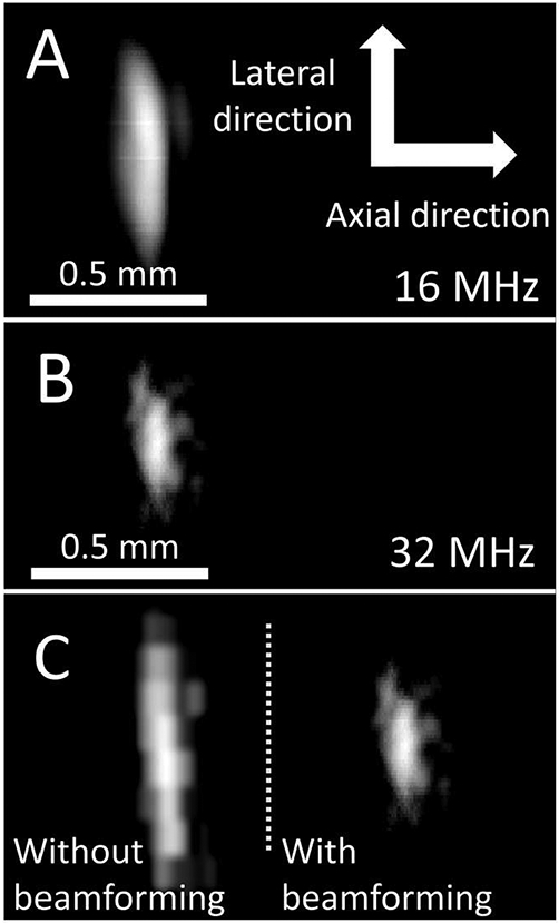
B-mode images of a 0.2 mm wire target at a depth of 5 mm formed at (A) 16 MHz and (B) 32 MHz with the dual-band transducer (15 dB dynamic range). (C) Comparing the high-frequency image without (left) and with (right) beamforming shows that the −6 dB target width decreased by a factor of 2.3 with SAF. Scale is constant in A-C, and axial and lateral dimensions (indicated in A) are displayed with equal scale.
In addition, the transducer was used to image a speckle-producing phantom. The B-mode image using the low-frequency band allowed for high penetration, while the high-frequency band led to a B-mode image with higher spatial resolution (Fig. 9). Speckle SNR values were 1.95 ± 0.26 and 1.56 ± 0.25 at 16 MHz and 32 MHz, respectively. Measuring penetration depth as the depth at which the amplitude decreased to −20 dB or −6 dB of the maximum value, penetration depth at 32 MHz was 7.5 mm (−20 dB) and 5.0 mm (−6 dB). Penetration depth at 16 MHz was 13.0 mm (−20 dB) and 7.35 mm (−6 dB). Additionally, insets in Fig. 9B show a magnified region of the phantom image processed with and without synthetic aperture beamforming, which show that using the expanded aperture improved spatial resolution and SNR.
Fig. 9.

B-mode images of a speckle-producing phantom formed using the (A) low and (B) high-frequency band of the dual-band transducer. While low-frequency imaging allows for greater penetration, high-frequency imaging shows higher spatial resolution. Images are displayed with dynamic ranges of 45 and 35 dB, respectively. Inlays in (B) with no beamforming (i) and with synthetic aperture beamforming (ii) show improved SNR and higher spatial resolution with beamforming.
C. Visualization of Ex Vivo Porcine Arteries
To assess system feasibility and image quality, images were formed from the acquired RF data with robotic steering during acquisition. Reconstructed views of the 3D dataset acquired for the porcine artery with the experimental setup in Fig. 10A-B show visualization of the artery wall and its lumen in 2D B-mode images (Fig. 10C-D). The low-frequency image reveals deep structural information due to higher penetration depth, and the low-frequency image shows small features that are resolved due to higher spatial resolution.
Fig. 10.

(A) Illustration of vessel orientation relative to the guidewire-based imaging system during acquisition of ex vivo porcine artery data, including (B) cross sectional view seen during imaging. B-mode image of vessel cross section acquired using (C) low and (D) high-frequency band of the dual-frequency transducer. Images in (C) and (D) are displayed with 40 and 30 dB dynamic range, respectively.
Figure 11 shows comparisons of images formed with the low and high frequency bands for both cross sections and 3D reconstructions. The 3D reconstructions (Fig. 11) of the ex vivo artery allow visualization of the vessel wall and lumen. Scale bar represents 5 mm in the lateral and elevational directions (depth dimension extended for display; see Fig. 10C-D for quantitative depth information). Low and high frequency images (Fig. 11A-B) reflect the findings from the cross-sectional views (Fig. 10). In addition, with high-frequency data overlaid onto low frequency data (Fig. 11C), the differences in penetration depth and resolved feature size can be observed. Finally, by implementing a depth-dependent weighted sum of the two datasets, the high-resolution imaging benefits of the 32 MHz band were maintained near the transducer, while the high penetration depth of the 16 MHz imaging was retained at greater depths (Fig. 11D).
Fig. 11.

Reconstructed 3D volumes of ex vivo porcine arteries images acquired with the developed transducer are shown for five different angles (top to bottom) for (A) 16 MHz only, (B) 32 MHz only, (C) combined with 16 MHz data in gray and 32 MHz data in blue, and (D) fused 16 and 32 MHz data using a weighted sum. The transducer is positioned looking into the artery, i.e. at the top looking down for the 0° view. Enlarged views of (C) at 0° and 106° are provided to emphasize advantages of 16 and 32 MHz images, which provide high penetration and high spatial resolution, respectively.
IV. Discussion
We have described the development of a single piezoelectric transducer that allows simultaneous high resolution and high penetration depth imaging for guiding a robotically steerable guidewire. Integrating imaging with the robotic guidewire allows for visualization of possible paths in front of the guidewire tip as well as nearby structural information, which may improve outcomes of peripheral revascularization in heavily calcified, chronically-occluded vessels in which guidewires are currently routed manually with only fluoroscopy. Due to the size of the system (0.89 mm diameter), a viable system can only have a single electrical connection, thus the presented design provides simultaneous dual-band performance for imaging with both high spatial resolution and high penetration.
Images of wire targets and speckle-producing phantoms are formed using the developed system with synthetic aperture focusing. The presented results demonstrate feasibility of the novel transducer design operating at two frequencies with a continuous, laser-micromachined structure and a single electrical connection. The integrated forward-viewing, robotically-steerable system allows high-resolution visualization of superficial structures and high-penetration imaging of deep structures in a sub-millimeter device.
A. Transducer Characterization and Performance
The measured center frequency of the high-frequency band (32 MHz) was slightly lower than the expected center frequency of 34 MHz. This minor deviation was likely the result of fabricated pillar height being slightly taller than designed, as a 0.003 mm difference would lead to a 32 MHz center frequency. Additionally, while the low-frequency band displayed relatively broad bandwidth (73%), the bandwidth of the high-frequency band was 23%. In the future, to improve bandwidth and axial resolution, an additional acoustic matching layer should be added to the design. It should also be noted that 73% fractional bandwidth reflects the −6 dB width of the signal, although the spectrum fluctuates with local minima at approximately 11 and 14 MHz, representing a reduction in bandwidth due to reverberation in the transducer that does not reduce the nominal fractional bandwidth. We varied parameters in simulations to find the cause, and we believe that the loaded epoxy backing had a lower concentration of aluminum particles than intended (lowering acoustic impedance), which resulted in a larger reflection at the back of the PZT.
For a 0.2 mm wire, measured target widths for low and high frequency bands were 0.498 ± 0.02 mm and 0.268 ± 0.01 mm, respectively. Additional improvements in the point spread function might be realized by applying adaptive methods [85]-[87]. Also, while the beamformed data had SNR values of 33 and 21 dB (Fig. 9-11), increased SNR would allow for 1) increased imaging depth at 32 MHz, and 2) increased Doppler CNR for imaging blood flow in the lumen. In the future, rather than exciting the transducer with a short impulse, transmitting waveforms consisting of the sum of windowed sinusoids at the two frequencies would increase energy transmitted into the body and thus SNR. With the transducer and excitation strategy utilized in this paper, the depth at which the 32 MHz signal decreased to −20 dB of the peak value was 7.5 mm, while at 16 MHz, the equivalent depth was 13.0 mm, allowing visualization of deeper structures (Fig. 10).
The goal of this research was to develop the first sub-millimeter forward-viewing transducer capable of multi-frequency imaging. As described in Methods, the effect of vibrational cross-coupling between pillars on beam width and pulse length was investigated. An ex vivo artery was imaged at both frequencies simultaneously (Fig. 10-11). In this design, the low and high frequency pillars are connected mechanically and operate in parallel electrically, while vibrations between pillars were reduced to maintain sensitivity for each frequency band. Further modeling studies may improve performance by varying the dimensions of the isolation notch and pillars to maximize sensitivity.
B. Visualization of Ex Vivo Porcine Arteries
The 0.035”-diameter, dual-band transducer was integrated with the robotically-steerable guidewire and used to acquire 3D imaging data of an ex vivo porcine artery. As expected, 32 MHz images have higher spatial resolution, which allowed fine features to be resolved that were not resolved at 16 MHz. Simultaneously, 16 MHz imaging provided visualization of morphological information even at increased depth. While a single high-frequency element could achieve high-resolution imaging, high penetration depth imaging is also needed to guide the steerable guidewire around tortuous vessels and beyond long occlusions. As shown, the 3D reconstructions can be displayed as an overlay or as a combined volume that maintains the high resolution of the high frequency band while incorporating the low frequency band data to increase scan depth. End-user feedback will be useful for determining which display adds the most value for interventionalists operating the system.
C. Future Considerations
For this study, image reconstruction was performed offline in MATLAB, and each B-mode image required < 10 seconds. However, when the guidewire is used to guide interventional procedures, image reconstruction can be performed using precomputed delays and thresholds (Section IIC), while parallelizing pixel-based beamforming to further reduce computation time. Given the small field of view and low number of scanlines relative to conventional array-based imaging, computational expense is quite low, meaning real-time imaging (i.e. frame rates ≥ 30 Hz) with concurrent guidewire steering can be achieved. In fact, another group recently showed magnetically-steered scanning for photoacoustic imaging with a cross-sectional frame rate of 400 Hz [88], supporting the feasibility of real time-imaging with the proposed approach.
In this work, image quality of reconstructed images benefited greatly from synthetic aperture beamforming. Given that a typical beamsum included 20 lines, the SNR improvement of 13 dB aligns with theoretical expectations, i.e. 13 dB is approximately . Additionally, the inclusion criterion expanded the effective aperture approximately three-fold, resulting in lateral resolution improvement of a factor of three. However, improvement in lateral resolution due to beamforming depends on scan geometry. In an environment that prevents large movements, the expanded aperture would have a smaller size, resulting in smaller improvements to lateral resolution. While subject to this limitation, forming images with synthetic aperture focusing while acquiring multiple lines with a high pulse repetition frequency results in dramatic improvements to SNR approximately proportional to the square root of the number of acquisitions and increased lateral resolution proportional to the width of the expanded aperture. In the future, a robotic guidewire with steering near the tip could increase the number acquisitions even in small arteries. Additionally, in the future, data will be acquired with a pulse repetition frequency of ~2 kHz to increase the SNR benefit of beamforming, and the beamforming criterion can be refined for aperture size, frequency, and target depth.
Based on the goals of imaging with penetration depth of at least 10 mm and resolution of 0.28 mm to resolve channels in chronic total occlusions, the developed device achieved desired imaging performance because axial resolution was <0.100 mm and lateral resolution was ~0.250 mm at a depth of 5 mm, and penetration depth > 10 mm was achieved. Additionally, the contrast and SNR were sufficient to visualize the vessel wall and its composition. In the future, SNR could be improved with an additional matching layer, and excitation with a multi-cycle pulse rather than an impulse would increase transmit intensity and thus SNR.
The presented work characterized the performance and demonstrated imaging capabilities of a new guidewire-based imaging system operating simultaneously at two frequencies. Finite element modeling (and subsequent experimental results) showed that the proposed design provides imaging that achieves the spatial resolution and sensitivity goals, despite low levels of mechanical coupling that are not present in traditional single-frequency piston designs. In the dual-frequency design with connected pillars, pulse lengths were 0.142 mm for the low-frequency signal and 0.075 mm for the high-frequency signal, which represent differences of less than 0.01 mm relative to single element, uncoupled designs. With carefully chosen pillar aspect ratios and isolation notches to reduce mechanical coupling, multi-frequency imaging with a single piezoelectric structure can be achieved. Additional work is required to test the imaging-guided navigation of the guidewire through small channels in a vascular environment with calcified occlusions. Additionally, future work will focus on developing the processing to segment 3D reconstructions in order to visualize local structures and determine viable paths around occlusions. The resulting images must be integrated into the robotic control system, and a virtual environment for path planning will be developed to improve navigation.
In addition, future work will also investigate image formation in the presence of tissue motion. As the guidewire tip can be steered rapidly, short data acquisition times can be achieved, though further investigations are required in order to develop a scheme for updating the display as the guidewire is mechanically translated in the presence of physiological motion.
When translating the guidewire tip, large errors in the position of the aperture would degrade images formed with mechanically-steered imaging, as previously investigated in [89]-[92]. However, coherent images were formed with significantly higher SNR and spatial resolution as a result of beamforming, indicating that the level of error was minimal. In the future, if aperture position error results in degradation of image quality, phase correction strategies could be used [93], [94].
While the robotic guidewire was essential for the formation of an expanded aperture while imaging, the steerable guidewire also allows navigation through spaces that are difficult or impossible without robotic control of the guidewire. Furthermore, in addition to small size, steerability, and integrated imaging, an interventional device must tolerate external forces when used to push through the lesion. This flexibility and durability will need to be evaluated in future testing in phantoms and in vivo.
COMSOL modeling showed that the multi-pillar design has a minor (<0.010 mm) impact on pulse length, and the fabricated dual-frequency transducer was able to produce pulses with lengths < 0.100 mm for each frequency band (Fig. 7). When the pulse lengths produced by the fabricated transducer with sinusoidal excitation were compared to the pulse lengths in simulations, the difference in pulse length was <0.015 mm. Additionally, the simulated and experimental results show that the proposed dual-frequency design can have acceptable main lobe width and clutter level, particularly when used with synthetic aperture beamforming. For the experimental data, −6 dB target widths were 0.50 mm and 0.27 mm for 16 MHz and 32 MHz images, compared to 0.49 mm and 0.22 mm for 17 MHz and 34 MHz simulated images.
Finally, nonlinearity in the imaging process (e.g. nonlinear propagation) could result in received echo signals containing frequency components that did not originate in the transmitted pulse. Due to the low acoustic pressures, harmonic generation signal is not expected to have a significant impact on the image quality of the high frequency image, although this would require further investigation.
V. Conclusion
This paper demonstrates the first single-cable, dual resonance transducer with two independent pillars operating in thickness mode. using a design machined from a single piece of PZT, the developed transducer allows simultaneous imaging with frequency bands centered at 16 and 32 MHz. The developed system was demonstrated in imaging experiments for visualization of wire targets in water, speckle-producing phantoms, and 3D imaging of an ex vivo porcine artery. With further development, the proposed vascular system with integrated forward-viewing ultrasound and a dexterous guidewire tip could increase procedural success in difficult CTO cases by improving navigation relative to manual advancement of guidewires under the guidance of fluoroscopy alone, reducing the percentage of revascularization procedures that are failures due to the inability to route the guidewire beyond calcified CTOs.
Acknowledgments
Research reported in this publication was supported in part by the National Institutes of Health under Award Number R01HL144714. Some of the work was performed at the Georgia Tech Institute for Electronics and Nanotechnology, a member of the National Nanotechnology Coordinated Infrastructure (NNCI), which is supported by the National Science Foundation (ECCS-2025462). The content is solely the responsibility of the authors and does not necessarily represent the official views of the National Institutes of Health or the National Science Foundation.
Biography

Graham C. Collins (Student Member, IEEE) was born in North Carolina, USA, in 1994. He received the B.S. degree in biomedical engineering from the University of North Carolina at Chapel Hill in 2017 and is currently a PhD Candidate in the joint Coulter Department of Biomedical Engineering at the Georgia Institute of Technology and Emory University in Atlanta, Georgia, USA.
Graham conducts research in the Ultrasonic Imaging and Instrumentation Laboratory at Georgia Institute of Technology, with a focus on imaging for interventional procedures, including transducer design/fabrication, blood flow imaging, ultrasound image formation, and signal processing.

Timothy A. Brumfiel received the B.S. degree in mechanical engineering, in 2020, from the Georgia Institute of Technology, Atlanta, GA, USA, where he is currently working toward the Ph.D. degree in robotics with the Medical Robotics and Automation (RoboMed) Laboratory. Timothy’s research interests include mechanism design, medical imaging, medical robot modeling, state estimation, and control.

Zachary L. Bercu received the A.B. degree in Psychology from Harvard University in Cambridge, Massachusetts, USA, and the MD degree in 2009 from Emory University, Atlanta, Georgia, USA. Dr. Bercu completed residency and a fellowship in Interventional Radiology at Mount Sinai in New York, New York, USA.
Dr. Bercu is currently Associate Professor of Radiology and Imaging Sciences and Assistant Program Director for Interventional Radiology Residency and Fellowship Program at Emory University School of Medicine. He is a member of the American College of Radiology, American Heart Association, and Association of Program Directors in Interventional Radiology. He has been named a distinguished reviewer for Cardiovascular and Interventional Radiology (CVIR). Currently, His research interests lie in medical device innovation, peripheral artery disease, and international collaboration in endovascular and interventional radiology clinical and research projects. Dr. Bercu serves on the Steering Committee for the Georgia Center for Medical Robotics.

Jaydev P. Desai (Fellow, IEEE) received the undergraduate degree in mechanical engineering from the Indian Institute of Technology Bombay, Mumbai, India, in 1993, the M.A. degree in mathematics in 1997, and M.S. and Ph.D. degree in mechanical engineering and applied mechanics from the University of Pennsylvania, Philadelphia, PA, USA, in 1995 and 1998, respectively. He is currently a Professor in the Wallace H. Coulter Department of Biomedical Engineering and holds the G.P. “Bud” Peterson and Valerie H. Peterson Faculty Professorship in Pediatric Research at the Georgia Institute of Technology.
Dr. Desai is also the Director of the Georgia Center for Medical Robotics and the Associate Director of the Institute for Robotics and Intelligent Machines. His research interests include image-guided surgical robotics, MEMS-based cancer diagnosis, endovascular robotics, and rehabilitation robotics. Dr. Desai is a recipient of several NIH R01 and NSF CAREER awards. He is the Editor-in-Chief of the Journal of Medical Robotics Research and the Encyclopedia of Medical Robotics. He is also a Fellow of the ASME and AIMBE

Brooks D. Lindsey (Member, IEEE) received the B.S. degree in electrical engineering from the University of Illinois at Urbana⣓Champaign, IL, USA, and the Ph.D. degree in biomedical engineering from Duke University, Durham, NC, USA. He completed postdoctoral training in the Joint Department of Biomedical Engineering, University of North Carolina at Chapel Hill, Chapel Hill, NC, and North Carolina State University, Raleigh, NC. In 2017, he joined The Wallace H. Coulter Department of Biomedical Engineering, Georgia Institute of Technology and Emory University, Atlanta, GA, USA, as an Assistant Professor, where he directs the Ultrasonic Imaging and Instrumentation Laboratory. His research interests include interventional imaging and development of ultrasound transducers and systems
Contributor Information
Graham C. Collins, Georgia Institute of Technology, Atlanta, GA, USA.
Timothy Brumfiel, Georgia Institute of Technology, Atlanta, GA, USA.
Zachary L. Bercu, Emory University Interventional Radiology
Jaydev P. Desai, Georgia Institute of Technology, Atlanta, GA, USA.
Brooks D. Lindsey, Georgia Institute of Technology, Atlanta, GA, USA.
References
- [1].Nehler MR et al. , “Epidemiology of peripheral arterial disease and critical limb ischemia in an insured national population,” Journal of Vascular Surgery, vol. 60, no. 3, pp. 686–695.e2, Sep. 2014, doi: 10.1016/j.jvs.2014.03.290. [DOI] [PubMed] [Google Scholar]
- [2].Song P et al. , “Global, regional, and national prevalence and risk factors for peripheral artery disease in 2015: an updated systematic review and analysis,” The Lancet Global Health, vol. 7, no. 8, pp. e1020–e1030, Aug. 2019, doi: 10.1016/S2214-109X(19)30255-4. [DOI] [PubMed] [Google Scholar]
- [3].Fowkes FGR, Aboyans V, Fowkes FJI, McDermott MM, Sampson UKA, and Criqui MH, “Peripheral artery disease: epidemiology and global perspectives,” Nature Reviews Cardiology, vol. 14, no. 3, pp. 156–170, Mar. 2017, doi: 10.1038/nrcardio.2016.179. [DOI] [PubMed] [Google Scholar]
- [4].Navneet Narula et al. , “Pathology of Peripheral Artery Disease in Patients With Critical Limb Ischemia,” Journal of the American College of Cardiology, vol. 72, no. 18, pp. 2152–2163, Oct. 2018, doi: 10.1016/j.jacc.2018.08.002. [DOI] [PubMed] [Google Scholar]
- [5].Rogers JH and Laird JR, “Overview of new technologies for lower extremity revascularization,” Circulation, vol. 116, no. 18, pp. 2072–2085, 2007. [DOI] [PubMed] [Google Scholar]
- [6].Zeller T et al. , “Two-year results after directional atherectomy of infrapopliteal arteries with the SilverHawk device,” J Endovasc Ther, vol. 14, no. 2, pp. 232–240, Apr. 2007, doi: 10.1177/152660280701400216. [DOI] [PubMed] [Google Scholar]
- [7].Hong J et al. , “A Dual-Mode Imaging Catheter for Intravascular Ultrasound Application,” IEEE Trans Med Imaging, vol. 38, no. 3, pp. 657–663, Mar. 2019, doi: 10.1109/TMI.2018.2869942. [DOI] [PubMed] [Google Scholar]
- [8].Fei C et al. , “PMN-PT Single Crystal Ultrasonic Transducer With Half-Concave Geometric Design for IVUS Imaging,” IEEE Transactions on Biomedical Engineering, vol. 65, no. 9, pp. 2087–2092, Sep. 2018, doi: 10.1109/TBME.2017.2784437. [DOI] [PubMed] [Google Scholar]
- [9].Ma T et al. , “Multi-frequency intravascular ultrasound (IVUS) imaging,” IEEE Trans Ultrason Ferroelectr Freq Control, vol. 62, no. 1, pp. 97–107, Jan. 2015, doi: 10.1109/TUFFC.2014.006679. [DOI] [PMC free article] [PubMed] [Google Scholar]
- [10].Beckman JA, Schneider PA, and Conte MS, “Advances in Revascularization for Peripheral Artery Disease: Revascularization in PAD,” Circ Res, vol. 128, no. 12, pp. 1885–1912, Jun. 2021, doi: 10.1161/CIRCRESAHA.121.318261. [DOI] [PubMed] [Google Scholar]
- [11].Hiramoto JS, Teraa M, de Borst GJ, and Conte MS, “Interventions for lower extremity peripheral artery disease,” Nat Rev Cardiol, vol. 15, no. 6, pp. 332–350, Jun. 2018, doi: 10.1038/s41569-018-0005-0. [DOI] [PubMed] [Google Scholar]
- [12].Shishehbor MH and Jaff MR, “Percutaneous Therapies for Peripheral Artery Disease,” Circulation, vol. 134, no. 24, pp. 2008–2027, Dec. 2016, doi: 10.1161/CIRCULATIONAHA.116.022546. [DOI] [PubMed] [Google Scholar]
- [13].Hardman RL, Jazaeri O, Yi J, Smith M, and Gupta R, “Overview of classification systems in peripheral artery disease,” Semin Intervent Radiol, vol. 31, no. 4, pp. 378–388, Dec. 2014, doi: 10.1055/s-0034-1393976. [DOI] [PMC free article] [PubMed] [Google Scholar]
- [14].Francois TH, Villanueva FS, and Chen X, “Radial modulation contrast imaging using a 20-MHz single-element intravascular ultrasound catheter,” IEEE transactions on ultrasonics, ferroelectrics, and frequency control, vol. 61, no. 5, pp. 779–791, 2014. [DOI] [PMC free article] [PubMed] [Google Scholar]
- [15].Jeong S, Chitalia Y, and Desai JP, “Design, Modeling, and Control of a Coaxially Aligned Steerable (COAST) Guidewire Robot,” IEEE Robotics and Automation Letters, pp. 1–1, 2020, doi: 10.1109/LRA.2020.3004782. [DOI] [Google Scholar]
- [16].Zhou J et al. “Intravascular Ultrasound Versus Angiography-Guided Drug-Eluting Stent Implantation: A Health Economic Analysis,” Circulation: Cardiovascular Quality and Outcomes, vol. 14, no. 5, p. e006789, May 2021, doi: 10.1161/CIRCOUTCOMES.120.006789. [DOI] [PubMed] [Google Scholar]
- [17].Oh S, Hong YJ, Kim JH, Ahn Y, and Jeong MH, “Intravascular Ultrasound-Guided Stent Implantation for the Focal Stenosis in the Middle Shaft of Twenty-Year Left Internal Mammary Artery Graft,” Chonnam Medical Journal, vol. 57, no. 2, p. 164, 2021, doi: 10.4068/cmj.2021.57.2.164. [DOI] [PMC free article] [PubMed] [Google Scholar]
- [18].von Hessling A, del Castillo TR, Karwacki G, and Roos JE, “The Columbus steerable guidewire in neurointerventions: early clinical experience and applications,” Journal of NeuroInterventional Surgery, May 2021, doi: 10.1136/neurintsurg-2021-017296. [DOI] [PMC free article] [PubMed] [Google Scholar]
- [19].Sinclair H, Bourantas C, Bagnall A, Mintz GS, and Kunadian V, “OCT for the Identification of Vulnerable Plaque in Acute Coronary Syndrome,” JACC: Cardiovascular Imaging, vol. 8, no. 2, pp. 198–209, Feb. 2015, doi: 10.1016/j.jcmg.2014.12.005. [DOI] [PubMed] [Google Scholar]
- [20].Farooq MU, Khasnis A, Majid A, and Kassab MY, “The role of optical coherence tomography in vascular medicine,” Vasc Med, vol. 14, no. 1, pp. 63–71, Feb. 2009, doi: 10.1177/1358863 × 08095153. [DOI] [PubMed] [Google Scholar]
- [21].Waksman R, Kitabata H, Prati F, Albertucci M, and Mintz GS, “Intravascular Ultrasound Versus Optical Coherence Tomography Guidance,” Journal of the American College of Cardiology, vol. 62, no. 17_Supplement, pp. S32–S40, Oct. 2013, doi: 10.1016/j.jacc.2013.08.709. [DOI] [PubMed] [Google Scholar]
- [22].Ali ZA et al. , “Optical coherence tomography compared with intravascular ultrasound and with angiography to guide coronary stent implantation (ILUMIEN III: OPTIMIZE PCI): a randomised controlled trial,” The Lancet, vol. 388, no. 10060, pp. 2618–2628, Nov. 2016, doi: 10.1016/S0140-6736(16)31922-5. [DOI] [PubMed] [Google Scholar]
- [23].Bezerra HG et al. , “Optical Coherence Tomography Versus Intravascular Ultrasound to Evaluate Coronary Artery Disease and Percutaneous Coronary Intervention,” JACC: Cardiovascular Interventions, vol. 6, no. 3, pp. 228–236, Mar. 2013, doi: 10.1016/j.jcin.2012.09.017. [DOI] [PubMed] [Google Scholar]
- [24].Parviz Y et al. , “Utility of intracoronary imaging in the cardiac catheterization laboratory: comprehensive evaluation with intravascular ultrasound and optical coherence tomography,” British medical bulletin, 2018. [DOI] [PubMed] [Google Scholar]
- [25].Kang S and Lee DY, “Hydraulically Steerable Micro Guidewire Capable of Distal Sharp Steering,” IEEE Transactions on Biomedical Engineering, vol. 68, no. 2, pp. 728–735, Feb. 2021, doi: 10.1109/TBME.2020.3013267. [DOI] [PubMed] [Google Scholar]
- [26].Lalande V et al. , “In vivo demonstration of magnetic guidewire steerability in a MRI system with additional gradient coils,” Medical Physics, vol. 42, no. 2, pp. 969–976, 2015, doi: 10.1118/1.4906194. [DOI] [PubMed] [Google Scholar]
- [27].Hwang J, Kim J, and Choi H, “A review of magnetic actuation systems and magnetically actuated guidewire- and catheter-based microrobots for vascular interventions,” Intel Serv Robotics, vol. 13, no. 1, pp. 1–14, Jan. 2020, doi: 10.1007/s11370-020-00311-0. [DOI] [Google Scholar]
- [28].Yang Z, Yang L, Zhang M, Wang Q, Yu SCH, and Zhang L, “Magnetic Control of a Steerable Guidewire Under Ultrasound Guidance Using Mobile Electromagnets,” IEEE Robotics and Automation Letters, vol. 6, no. 2, pp. 1280–1287, Apr. 2021, doi: 10.1109/LRA.2021.3057295. [DOI] [Google Scholar]
- [29].Park J, Lee C, Lee J, Ha J-I, Choi H, and Chang JH, “Magnetically Actuated Forward-Looking Interventional Ultrasound Imaging: Feasibility Studies,” IEEE Trans Biomed Eng, vol. 67, no. 6, pp. 1797–1805, Jun. 2020, doi: 10.1109/TBME.2019.2948391. [DOI] [PubMed] [Google Scholar]
- [30].Camarillo DB, Milne CF, Carlson CR, Zinn MR, and Salisbury JK, “Mechanics modeling of tendon-driven continuum manipulators,” IEEE Transactions on Robotics, vol. 24, no. 6, pp. 1262–1273, 2008. [Google Scholar]
- [31].Kim K, Woo H, and Suh J, “Design and evaluation of a continuum robot with discreted link joints for cardiovascular interventions,” in 2018 7th IEEE International Conference on Biomedical Robotics and Biomechatronics (Biorob), 2018, pp. 627–633. [Google Scholar]
- [32].Ataollahi A et al. , “Three-Degree-of-Freedom MR-Compatible Multi-segment Cardiac Catheter Steering Mechanism,” IEEE Transactions on Biomedical Engineering, vol. 63, no. 11, pp. 2425–2435, Nov. 2016, doi: 10.1109/TBME.2013.2276739. [DOI] [PubMed] [Google Scholar]
- [33].Song J, Gonenc B, Guo J, and Iordachita I, “Intraocular Snake Integrated with the Steady-Hand Eye Robot for Assisted Retinal Micro-surgery,” IEEE Int Conf Robot Autom, vol. 2017, pp. 6724–6729, 2017, doi: 10.1109/ICRA.2017.7989796. [DOI] [PMC free article] [PubMed] [Google Scholar]
- [34].Chitalia Y, Wang X, and Desai JP, “Design, Modeling and Control of a 2-DoF Robotic Guidewire,” in 2018 IEEE International Conference on Robotics and Automation (ICRA), May 2018, pp. 32–37. doi: 10.1109/ICRA.2018.8462694. [DOI] [Google Scholar]
- [35].Collins G, Sarma A, Bercu ZL, Desai JP, and Lindsey B, “A Robotically Steerable Guidewire with Forward-Viewing Ultrasound: Development of Technology for Minimally-Invasive Imaging,” IEEE Transactions on Biomedical Engineering, 2020. [DOI] [PMC free article] [PubMed] [Google Scholar]
- [36].Chee RKW, Zhang P, Maadi M, and Zemp RJ, “Multifrequency Interlaced CMUTs for Photoacoustic Imaging,” IEEE Transactions on Ultrasonics, Ferroelectrics, and Frequency Control, vol. 64, no. 2, pp. 391–401, Feb. 2017, doi: 10.1109/TUFFC.2016.2620381. [DOI] [PubMed] [Google Scholar]
- [37].Kshirsagar A et al. , “Multi-frequency CMUT arrays for imaging-therapy applications,” in 2013 IEEE International Ultrasonics Symposium (IUS), Jul. 2013, pp. 1991–1993. doi: 10.1109/ULT-SYM.2013.0508. [DOI] [Google Scholar]
- [38].Deng L, O’Reilly MA, Jones RM, An R, and Hynynen K, “A multi-frequency sparse hemispherical ultrasound phased array for microbubble-mediated transcranial therapy and simultaneous cavitation mapping,” Phys. Med. Biol, vol. 61, no. 24, pp. 8476–8501, Nov. 2016, doi: 10.1088/0031-9155/61/24/8476. [DOI] [PMC free article] [PubMed] [Google Scholar]
- [39].Munding CE et al. , “Development of a 3 French Dual-Frequency Intravascular Ultrasound Catheter,” Ultrasound in Medicine & Biology, vol. 44, no. 1, pp. 251–266, Jan. 2018, doi: 10.1016/j.ultrasmedbio.2017.09.015. [DOI] [PubMed] [Google Scholar]
- [40].Shih C-C, Chen P-Y, Ma T, Zhou Q, Shung KK, and Huang C-C, “Development of an intravascular ultrasound elastography based on a dual-element transducer,” Royal Society Open Science, vol. 5, no. 4, p. 180138, doi: 10.1098/rsos.180138. [DOI] [PMC free article] [PubMed] [Google Scholar]
- [41].Ma J et al. , “Design factors of intravascular dual frequency transducers for super-harmonic contrast imaging and acoustic angiography,” Phys. Med. Biol, vol. 60, no. 9, pp. 3441–3457, Apr. 2015, doi: 10.1088/0031-9155/60/9/3441. [DOI] [PMC free article] [PubMed] [Google Scholar]
- [42].Li Y et al. , “An Integrated System for Superharmonic Contrast-Enhanced Ultrasound Imaging: Design and Intravascular Phantom Imaging Study,” IEEE Transactions on Biomedical Engineering, vol. 63, no. 9, pp. 1933–1943, Sep. 2016, doi: 10.1109/TBME.2015.2506639. [DOI] [PMC free article] [PubMed] [Google Scholar]
- [43].Newsome IG et al. , “Implementation of a novel 288-element dual-frequency array for acoustic angiography: in vitro & in vivo characterization,” IEEE Transactions on Ultrasonics, Ferroelectrics, and Frequency Control, 2021. [DOI] [PMC free article] [PubMed] [Google Scholar]
- [44].Li S et al. , “A Dual-Frequency Colinear Array for Acoustic Angiography in Prostate Cancer Evaluation,” IEEE Transactions on Ultrasonics, Ferroelectrics, and Frequency Control, vol. 65, no. 12, pp. 2418–2428, Dec. 2018, doi: 10.1109/TUFFC.2018.2872911. [DOI] [PMC free article] [PubMed] [Google Scholar]
- [45].Lee J and Chang JH, “Dual-Element Intravascular Ultrasound Transducer for Tissue Harmonic Imaging and Frequency Compounding: Development and Imaging Performance Assessment,” IEEE Trans. Biomed. Eng, vol. 66, no. 11, pp. 3146–3155, Nov. 2019, doi: 10.1109/TBME.2019.2901005. [DOI] [PubMed] [Google Scholar]
- [46].Andersen KK, Frijlink ME, Johansen TF, and Hoff L, “A Dual-Frequency Coupled Resonator Transducer,” IEEE Transactions on Ultrasonics, Ferroelectrics, and Frequency Control, vol. 67, no. 10, pp. 2119–2129, Oct. 2020, doi: 10.1109/TUFFC.2020.2995305. [DOI] [PubMed] [Google Scholar]
- [47].Martin KH et al. , “Dual-Frequency Piezoelectric Transducers for Contrast Enhanced Ultrasound Imaging,” Sensors, vol. 14, no. 11, pp. 20825–20842, Nov. 2014, doi: 10.3390/s141120825. [DOI] [PMC free article] [PubMed] [Google Scholar]
- [48].Lindsey BD, Kim J, Dayton PA, and Jiang X, “Dual-Frequency Piezoelectric Endoscopic Transducer for Imaging Vascular Invasion in Pancreatic Cancer,” IEEE Transactions on Ultrasonics, Ferroelectrics, and Frequency Control, vol. 64, no. 7, pp. 1078–1086, Jul. 2017, doi: 10.1109/TUFFC.2017.2702010. [DOI] [PMC free article] [PubMed] [Google Scholar]
- [49].Peng C, Wu H, Kim S, Dai X, and Jiang X, “Recent Advances in Transducers for Intravascular Ultrasound (IVUS) Imaging,” Sensors, vol. 21, no. 10, p. 3540, Jan. 2021, doi: 10.3390/s21103540. [DOI] [PMC free article] [PubMed] [Google Scholar]
- [50].Qiu W, Chen Y, Wong C-M, Liu B, Dai J, and Zheng H, “A novel dual-frequency imaging method for intravascular ultrasound applications,” Ultrasonics, vol. 57, pp. 31–35, Mar. 2015, doi: 10.1016/j.ultras.2014.10.011. [DOI] [PubMed] [Google Scholar]
- [51].Munding CE, Chérin E, Alves N, Goertz DE, Courtney BK, and Foster FS, “30/80 MHz Bidirectional Dual-Frequency IVUS Feasibility Evaluated In Vivo and for Stent Imaging,” Ultrasound in Medicine & Biology, May 2020, doi: 10.1016/j.ultrasmedbio.2020.03.032. [DOI] [PubMed] [Google Scholar]
- [52].Sun C, Shi Q, Yazici MS, Kobayashi T, Liu Y, and Lee C, “Investigation of Broadband Characteristics of Multi-Frequency Piezoelectric Micromachined Ultrasonic Transducer (MF-pMUT),” IEEE Sensors Journal, vol. 19, no. 3, pp. 860–867, Feb. 2019, doi: 10.1109/JSEN.2018.2878785. [DOI] [Google Scholar]
- [53].Wang Z, Ma J, Jiang X, Martin KH, and Dayton PA, “An array transmitter for dual-frequency contrast enhanced intravascular ultrasound imaging,” in 2014 IEEE International Ultrasonics Symposium, 2014, pp. 2104–2107. [Google Scholar]
- [54].Shao W, Li P, Li Z, Xu J, Jiao Y, and Cui Y, “A micro dual-frequency transducer based on contour-extensional vibration and thickness mode,” AIP Advances, vol. 8, no. 10, p. 105301, Oct. 2018, doi: 10.1063/1.5040787. [DOI] [Google Scholar]
- [55].Sung JH, Jeong EY, and Jeong JS, “Intravascular Ultrasound Transducer by Using Polarization Inversion Technique for Tissue Harmonic Imaging: Modeling and Experiments,” IEEE Trans Biomed Eng, vol. 67, no. 12, pp. 3380–3391, Dec. 2020, doi: 10.1109/TBME.2020.2986284. [DOI] [PubMed] [Google Scholar]
- [56].Park CY, Kwon DS, Sung JH, and Jeong JS, “Dual-frequency ultrasound transducer using inversion layer technique for therapeutic ultrasound surgery,” IEEE Sensors Journal, vol. 17, no. 21, pp. 6859–6866, 2017. [Google Scholar]
- [57].Wu L, Chen X, Wang G, and Zhou Q, “Dual-frequency piezoelectric micromachined ultrasonic transducers,” Appl. Phys. Lett, vol. 115, no. 2, p. 023501, Jul. 2019, doi: 10.1063/1.5097624. [DOI] [Google Scholar]
- [58].Lee J, Moon J-Y, and Chang JH, “A 35 MHz/105 MHz Dual-Element Focused Transducer for Intravascular Ultrasound Tissue Imaging Using the Third Harmonic,” Sensors (Basel), vol. 18, no. 7, Jul. 2018, doi: 10.3390/s18072290. [DOI] [PMC free article] [PubMed] [Google Scholar]
- [59].Mahmud MM et al. , “An Improved CMUT Structure Enabling Release and Collapse of the Plate in the Same Tx/Rx Cycle for Dual-Frequency Acoustic Angiography,” IEEE Transactions on Ultrasonics, Ferroelectrics, and Frequency Control, vol. 67, no. 11, pp. 2291–2302, Nov. 2020, doi: 10.1109/TUFFC.2020.3001221. [DOI] [PMC free article] [PubMed] [Google Scholar]
- [60].Maadi M, Ceroici C, and Zemp RJ, “Dual-Frequency CMUT Arrays for Multi-Band Ultrasound Imaging Applications,” IEEE Transactions on Ultrasonics, Ferroelectrics, and Frequency Control, pp. 1–1, 2021, doi: 10.1109/TUFFC.2021.3062071. [DOI] [PubMed] [Google Scholar]
- [61].UPPAL N, SHIAKOLAS P, and PRIYA S, “Micromachining of PZT Using Ultrafast Femtosecond Laser,” Ferroelectrics Letters Section, vol. 32, no. 3–4, pp. 67–77, 2005. [Google Scholar]
- [62].Di Maio Y, Colombier JP, Cazottes P, and Audouard E, “Ultrafast laser ablation characteristics of PZT ceramic: Analysis methods and comparison with metals,” Optics and Lasers in Engineering, vol. 50, no. 11, pp. 1582–1591, Nov. 2012, doi: 10.1016/j.optlaseng.2012.05.022. [DOI] [Google Scholar]
- [63].Mauclair C et al. , “Ultrafast laser micro-cutting of stainless steel and PZT using a modulated line of multiple foci formed by spatial beam shaping,” Optics and Lasers in Engineering, vol. 67, pp. 212–217, Apr. 2015, doi: 10.1016/j.optlaseng.2014.11.018. [DOI] [Google Scholar]
- [64].Lukacs M, Sayer M, Lockwood G, and Foster S, “Laser micromachined high frequency ultrasonic arrays,” in 1999 IEEE Ultrasonics Symposium. Proceedings. International Symposium (Cat. No.99CH37027), Oct. 1999, vol. 2, pp. 1209–1212 vol.2. doi: 10.1109/ULTSYM.1999.849214. [DOI] [Google Scholar]
- [65].Xu J et al. , “Micromachined High Frequency 1–3 Piezocomposite Transducer Using Picosecond Laser,” IEEE Transactions on Ultrasonics, Ferroelectrics, and Frequency Control, vol. 68, no. 6, pp. 2219–2226, Jun. 2021, doi: 10.1109/TUFFC.2021.3059942. [DOI] [PubMed] [Google Scholar]
- [66].Li Z, Lv J, Zhu X, Cui Y, and Jian X, “Development of high frequency piezocomposite with hexagonal pillars via cold ablation process,” Ultrasonics, vol. 114, p. 106404, Jul. 2021, doi: 10.1016/j.ultras.2021.106404. [DOI] [PubMed] [Google Scholar]
- [67].Su M et al. , “Cable-Shared Dual-Frequency Catheter for Intravascular Ultrasound,” IEEE Transactions on Ultrasonics, Ferroelectrics, and Frequency Control, vol. 66, no. 5, pp. 849–856, May 2019, doi: 10.1109/TUFFC.2019.2898256. [DOI] [PubMed] [Google Scholar]
- [68].Lim J, Tekes C, Degertekin FL, and Ghovanloo M, “Towards a Reduced-Wire Interface for CMUT-Based Intravascular Ultrasound Imaging Systems,” IEEE Transactions on Biomedical Circuits and Systems, vol. 11, no. 2, pp. 400–410, Apr. 2017, doi: 10.1109/TBCAS.2016.2592525. [DOI] [PMC free article] [PubMed] [Google Scholar]
- [69].Wang J, Zhou Z, and W YJT, “Capacitive micromachined ultrasound transducers for intravascular ultrasound imaging,” Microsystems & Nanoengineering; London, vol. 6, no. 1, 2020, doi: 10.1038/s41378-020-0181-z. [DOI] [PMC free article] [PubMed] [Google Scholar]
- [70].Gurun G, Hasler P, and Degertekin FL, “Front-end receiver electronics for high-frequency monolithic CMUT-on-CMOS imaging arrays,” IEEE Transactions on Ultrasonics, Ferroelectrics, and Frequency Control, vol. 58, no. 8, pp. 1658–1668, Aug. 2011, doi: 10.1109/TUFFC.2011.1993. [DOI] [PMC free article] [PubMed] [Google Scholar]
- [71].Tan M et al. , “A Front-End ASIC With High-Voltage Transmit Switching and Receive Digitization for 3-D Forward-Looking Intravascular Ultrasound Imaging,” IEEE J. Solid-State Circuits, vol. 53, no. 8, pp. 2284–2297, Aug. 2018, doi: 10.1109/JSSC.2018.2828826. [DOI] [Google Scholar]
- [72].Janjic J et al. , “A 2-D Ultrasound Transducer With Front-End ASIC and Low Cable Count for 3-D Forward-Looking Intravascular Imaging: Performance and Characterization,” IEEE Transactions on Ultrasonics, Ferroelectrics, and Frequency Control, vol. 65, no. 10, pp. 1832–1844, Oct. 2018, doi: 10.1109/TUFFC.2018.2859824. [DOI] [PubMed] [Google Scholar]
- [73].Degertekin FL, Guldiken RO, and Karaman M, “Annular-ring CMUT arrays for forward-looking IVUS: Transducer characterization and imaging,” IEEE transactions on ultrasonics, ferroelectrics, and frequency control, vol. 53, no. 2, pp. 474–482, 2006. [DOI] [PubMed] [Google Scholar]
- [74].Zahorian J et al. , “Monolithic CMUT-on-CMOS Integration for Intravascular Ultrasound Applications,” IEEE Transactions on Ultrasonics, Ferroelectrics, and Frequency Control, vol. 58, no. 12, pp. 2659–2667, Dec. 2011, doi: 10.1109/TUFFC.2011.2128. [DOI] [PMC free article] [PubMed] [Google Scholar]
- [75].Jensen JA, “Field: A program for simulating ultrasound systems,” 1996. [Google Scholar]
- [76].Lukacs M et al. , “Performance and characterization of high frequency linear arrays,” in IEEE Ultrasonics Symposium, 2005., 2005, vol. 1, pp. 105–108. [DOI] [PubMed] [Google Scholar]
- [77].Hadimioglu B and Khuri-Yakub BT, “Polymer films as acoustic matching layers,” in IEEE Symposium on Ultrasonics, Dec. 1990, pp. 1337–1340 vol.3. doi: 10.1109/ULTSYM.1990.171581. [DOI] [Google Scholar]
- [78].Li Z, Shao W, Zhu X, Lv J, Han Z, and Cui Y, “Parylene coating for 13 MHz 1-3 composite transducer performance enhancement - ScienceDirect,” Applied Acoustics, vol. 174, Mar. 2021. [Google Scholar]
- [79].Cabrera-Munoz NE et al. , “Forward-looking 30-MHz phased-array transducer for peripheral intravascular imaging,” Sensors and Actuators A : Physical, vol. 280, pp. 145–163, Sep. 2018, doi: 10.1016/j.sna.2018.07.035. [DOI] [Google Scholar]
- [80].Cannata JM, Ritter TA, Chen W-H, Silverman RH, and Shung KK, “Design of efficient, broadband single-element (20-80 MHz) ultrasonic transducers for medical imaging applications,” IEEE Transactions on Ultrasonics, Ferroelectrics, and Frequency Control, vol. 50, no. 11, pp. 1548–1557, Nov. 2003, doi: 10.1109/TUFFC.2003.1251138. [DOI] [PubMed] [Google Scholar]
- [81].Wu D-W, Zhou Q, Geng X, Liu C-G, Djuth F, and Shung KK, “Very high frequency (beyond 100 MHz) PZT kerfless linear arrays,” IEEE Transactions on Ultrasonics, Ferroelectrics, and Frequency Control, vol. 56, no. 10, pp. 2304–2310, Oct. 2009, doi: 10.1109/TUFFC.2009.1311. [DOI] [PMC free article] [PubMed] [Google Scholar]
- [82].Sarma A et al. , “Towards the Development of an Ultrasound-Guided Robotically Steerable Guidewire,” 2020 International Symposium on Medical Robotics (ISMR), Apr. 2020. [Google Scholar]
- [83].Collins GC, Jing B, and Lindsey BD, “High contrast power Doppler imaging in side-viewing intravascular ultrasound imaging via angular compounding,” Ultrasonics, vol. 108, p. 106200, Dec. 2020, doi: 10.1016/j.ultras.2020.106200. [DOI] [PMC free article] [PubMed] [Google Scholar]
- [84].Hayes BT, Merrick MA, Sandrey MA, and Cordova ML, “Three-MHz Ultrasound Heats Deeper Into the Tissues Than Originally Theorized,” J Athl Train, vol. 39, no. 3, pp. 230–234, 2004. [PMC free article] [PubMed] [Google Scholar]
- [85].Lindsey BD, Martin KH, Jiang X, and Dayton PA, “Adaptive windowing in contrast-enhanced intravascular ultrasound imaging,” Ultrasonics, vol. 70, pp. 123–135, Aug. 2016, doi: 10.1016/j.ultras.2016.04.022. [DOI] [PMC free article] [PubMed] [Google Scholar]
- [86].Yu M, Li Y, Ma T, Shung KK, and Zhou Q, “Intravascular Ultrasound Imaging With Virtual Source Synthetic Aperture Focusing and Coherence Factor Weighting,” IEEE Transactions on Medical Imaging, vol. 36, no. 10, pp. 2171–2178, Oct. 2017, doi: 10.1109/TMI.2017.2723479. [DOI] [PMC free article] [PubMed] [Google Scholar]
- [87].Kang S, Lee J, and Chang JH, “Effectiveness of synthetic aperture focusing and coherence factor weighting for intravascular ultrasound imaging,” Ultrasonics, vol. 113, p. 106364, May 2021, doi: 10.1016/j.ultras.2021.106364. [DOI] [PubMed] [Google Scholar]
- [88].Chen M et al. , “High-speed functional photoacoustic microscopy using a water-immersible two-axis torsion-bending scanner,” Photoacoustics, p. 100309, Oct. 2021, doi: 10.1016/j.pacs.2021.100309. [DOI] [PMC free article] [PubMed] [Google Scholar]
- [89].Zhang HK et al. , “Toward dynamic lumbar puncture guidance using needle-based single-element ultrasound imaging,” JMI, vol. 5, no. 2, p. 021224, Apr. 2018, doi: 10.1117/1.JMI.5.2.021224. [DOI] [PMC free article] [PubMed] [Google Scholar]
- [90].Zhang HK, Kim Y, Moghekar A, Durr NJ, and Boctor EM, “Single-Element Needle-Based Ultrasound Imaging of the Spine: An In Vivo Feasibility Study,” in Simulation, Image Processing, and Ultrasound Systems for Assisted Diagnosis and Navigation, Cham, 2018, pp. 82–89. doi: 10.1007/978-3-030-01045-4_10. [DOI] [Google Scholar]
- [91].Bottenus N et al. , “Feasibility of Swept Synthetic Aperture Ultrasound Imaging,” IEEE Trans Med Imaging, vol. 35, no. 7, pp. 1676–1685, Jul. 2016, doi: 10.1109/TMI.2016.2524992. [DOI] [PMC free article] [PubMed] [Google Scholar]
- [92].Zhang HK, Cheng A, Bottenus N, Guo X, Trahey GE, and Boctor EM, “Synthetic tracked aperture ultrasound imaging: design, simulation, and experimental evaluation,” J Med Imaging (Bellingham), vol. 3, no. 2, Apr. 2016, doi: 10.1117/1.JMI.3.2.027001. [DOI] [PMC free article] [PubMed] [Google Scholar]
- [93].Nock LF and Trahey GE, “Synthetic receive aperture imaging with phase correction for motion and for tissue inhomogeneities. I. Basic principles,” IEEE Transactions on Ultrasonics, Ferroelectrics, and Frequency Control, vol. 39, no. 4, pp. 489–495, Jul. 1992, doi: 10.1109/58.148539. [DOI] [PubMed] [Google Scholar]
- [94].Trahey GE and Nock LF, “Synthetic receive aperture imaging with phase correction for motion and for tissue inhomogeneities. II. Effects of and correction for motion,” IEEE Transactions on Ultrasonics, Ferroelectrics, and Frequency Control, vol. 39, no. 4, pp. 496–501, Jul. 1992, doi: 10.1109/58.148540. [DOI] [PubMed] [Google Scholar]