



Abstract
Acquiring CBCTs from a limited scan angle can help to reduce the imaging time, save the imaging dose, and allow continuous target localizations through arc-based treatments with high temporal resolution. However, insufficient scan angle sampling leads to severe distortions and artifacts in the reconstructed CBCT images, limiting their clinical applicability. 2D-3D deformable registration can map a prior fully-sampled CT/CBCT volume to estimate a new CBCT, based on limited-angle on-board cone-beam projections. The resulting CBCT images estimated by 2D-3D deformable registration can successfully suppress the distortions and artifacts, and reflect up-to-date patient anatomy through deformable registration. However, traditional iterative 2D-3D deformable registration algorithm is very computationally expensive and time-consuming, which takes hours to generate a high quality deformation vector field (DVF) and the CBCT. In this work, we developed an unsupervised, end-to-end, 2D-3D deformable registration framework using convolutional neural networks (2D3D-RegNet) to address the speed bottleneck of the conventional iterative 2D-3D deformable registration algorithm. The developed 2D3D-RegNet was able to solve the DVFs within 5 seconds for 90 orthogonally-arranged projections covering a combined 90° scan angle, with DVF accuracy superior to 3D-3D deformable registration, and on par with the conventional 2D-3D deformable registration algorithm. We also performed a preliminary robustness analysis of 2D3D-RegNet towards projection angular sampling frequency variations, as well as scan angle offsets. The synergy of 2D3D-RegNet with biomechanical modeling was also evaluated, and demonstrated that 2D3D-RegNet can function as a fast DVF solution core for further DVF refinement.
I. Introduction:
Accurate tumor targeting has been a frequent challenge in radiation therapy, in most scenarios due to anatomical motion and deformation between treatment fractions and within each fraction (Keall et al., 2006; Liu et al., 2014). Faster imaging allows more frequent target localizations, which can potentially track mobile tumors and pinpoint radiation beams towards them in real-time. Faster imaging may also translate into shorter patient on-board time, which may improve the treatment accuracy as longer on-board time was found positively correlated with the magnitude of target position deviations (Purdie et al., 2007; Ballhausen et al., 2018). However, due to the restrictions of currently-available imaging hardware, especially the rotational speed limit of the imaging arm, it usually takes ~1 minute or more to acquire a fully-sampled cone-beam computed tomography (CBCT), the current ‘gold-standard’ imaging technique used in most modern linear accelerator (LINAC) systems (Jaffray and Siewerdsen, 2000). Digital tomosynthesis (DTS), or limited-angle CBCT, which is acquired through a partial arc rotation, can improve the temporal resolution of imaging for faster target localization (Zhang et al., 2013a; Zhang et al., 2013b). It may also be necessary in scenarios where a full-gantry rotation may not be cleared due to peripheral treatment sites, or obstructions from ancillary supporting systems attached to the patient. A limited-angle acquisition also naturally reduces the overall imaging dose to patients, and may allow continuous tumor localizations through arc-based treatment deliveries (Ren et al., 2014; Zhang et al., 2017). However, the image quality of limited-angle CBCT is severely affected by the poor resolution along the direction perpendicular to the scan angle due to partial Fourier domain sampling (Davison, 1983; Zhang et al., 2013a). Previous studies have developed different approaches to improve the quality of the limited-angle CBCTs, while most of them can only remove partial of the artifacts, and usually still require a relatively large scan angle (>100°) for adequate image quality (Frikel and Quinto, 2013; Zhang et al., 2016a; Wurfl et al., 2018).
2D-3D deformable registration, which is a technique that solves a deformation vector field (DVF) to map a previously acquired fully-sampled CT/CBCT (source) to a new on-board CBCT (target) via 2D projection matching, can be particularly effective under the limited-angle sampling scenario (Ren et al., 2012; Wang and Gu, 2012; Zhang et al., 2013b; Zhang et al., 2016b). The combination of a priori high-quality information from the source image, and on-board information from limited-angle projections, can effectively mitigate the under-sampling issue to render high-quality on-board CBCT images. Instead of measuring the similarity directly between a deformed source image and the artifacts-ridden limited-angle CBCT image, 2D-3D deformable registration calculates the similarity between the projected digitally reconstructed radiographs (DRRs) of the deformed source image and the artifacts-free on-board projections. 2D-3D deformable registration has been investigated in recent years for its potential in sparse-view and limited-angle projection based CBCT estimation with very promising results (Brock et al., 2010; Ren et al., 2012). Recent developments also combined 2D-3D deformable registration with additional techniques, such as principal component analysis-based motion modeling, motion-compensated image reconstruction, or biomechanical modeling to further enhance its accuracy and applicability (Zhang et al., 2013b; Wang and Gu, 2013; Zhang et al., 2016b). However, the current 2D-3D deformable registration algorithms involve a computationally-expensive optimization scheme of costly forward- and back- projection operations, repeated DVF gradient computations, iterative step size searches, and numerous image interpolations. Although parallel acceleration schemes via graphics processing units (GPUs) has been introduced into the 2D-3D deformable registration for efficiency improvement, considerable runtimes up to hours are still needed to derive a high-accuracy DVF. A prohibitive runtime defeats the purpose of using limited-angle acquisition for fast on-board imaging and target localization, and limits its clinical deployment.
With the recent developments in artificial intelligence and machine learning, especially deep learning, many imaging-related tasks including segmentation, reconstruction, and rigid/deformable registration have been successfully implemented via deep convolutional neural networks (Wang et al., 2018; Rivenson et al., 2018; Balakrishnan et al., 2019; Fu et al., 2020). Packages including the Voxelmorph have been available to solve DVFs between images through deep neural networks within seconds at test time (Balakrishnan et al., 2019). However, those networks were designed to solve registrations between similar-quality 2D image pairs or 3D image pairs. No 2D-3D deformable registration has been attempted through a neural network framework yet. As the 2D-3D deformable registration is often based on sparse-view and limited-angle projections, it makes the deformable registration especially challenging as a high-quality target image is not available for the registration.
To address this issue, in this study, we developed an unsupervised, end-to-end, 2D-3D deformable registration network (2D3D-RegNet) on the basis of a core U-net structure, a popular network proved effective in handling various image domain tasks (Ronneberger et al., 2015). A simple Feldkamp-Davis-Kress (FDK) reconstruction module was included into the 2D3D-RegNet to align the 2D projections with the source image to feed into the U-net as parallel channels (Feldkamp et al., 1984). Forward-projection module was also included into the network to generate 2D DRRs from the deformed 3D source images to assess their match to 2D target cone-beam projections. A DVF inversion module was included in the 2D3D-RegNet to invert the forward DVF to promote inverse deformation consistency, which also adds additional constraints and regularizations for the ill-conditioned 2D-3D deformable registration problem. Different limited-angle sampling scenarios were simulated to evaluate the accuracy of 2D3D-RegNet against the traditional 2D-3D deformable registration algorithm, and against a mainstream, open-source deformable registration package (Elastix) (Klein et al., 2009). The feasibility and accuracy of combining 2D3D-RegNet with biomechanical modeling were also evaluated to demonstrate the utility of 2D3D-RegNet as a core for fast image registration and CBCT estimation.
II. Materials and Methods:
II.A. Network structures:
As shown in Fig. 1, the overall workflow of 2D3D-RegNet includes input channels (source image and target cone-beam projections), a reconstruction module, a U-net core, a forward-projection module and a DVF inversion module. The function and design of each of the modules were introduced as following:
Figure 1.
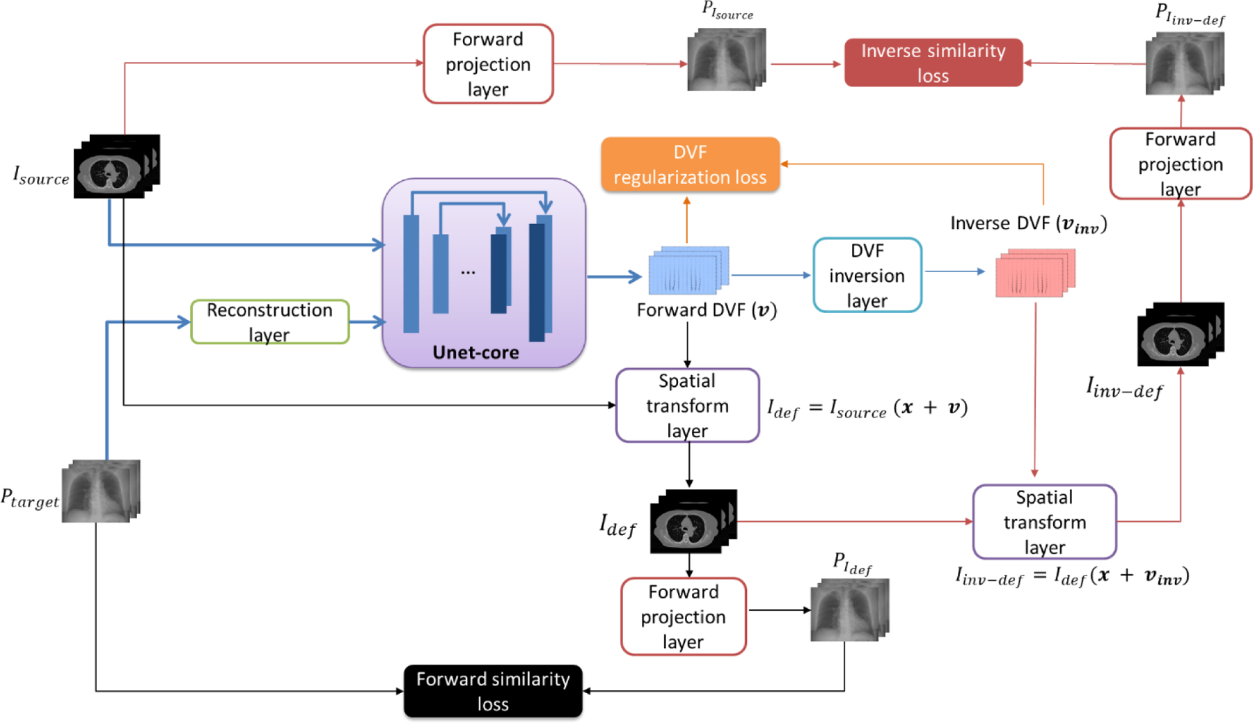
The overall 2D3D-RegNet structure and workflow.
II.A.1. Reconstruction Layer:
The input source 3D images and the cone-beam projections are of different physical properties, on different image reference frames, and also of different dimensionality and resolution. To align the two inputs as parallel channels that can be directly fed into the following U-net structure, in this study, we added a GPU-enabled, non-trainable reconstruction layer on the basis of the 3D FDK algorithm to convert the 2D projections into the 3D image domain (Feldkamp et al., 1984; Syben et al., 2019a). The FDK-reconstructed target image, as well as the source image, were concatenated as two channels to input into a following U-net core structure to solve the DVFs.
II.A.2. U-Net Core:
With a multi-layered encoder and decoder structure, the U-net has been widely used for image registration studies for its capability of capturing both global structure changes and local variations, and generating voxel-wise DVFs (Eppenhof and Pluim, 2018; Balakrishnan et al., 2019). In this study, same as Voxelmorph, we used U-net as the core structure to generate the DVFs. The core U-net structure starts with a 16-filter convolutional layer, which was followed by four down-sampling convolutional layers (with a stride of two) of 16, 32, 32, and 32 filters, respectively. The expansive path features four layers symmetric to the contractive path, with each layer composed of up-sampling, concatenating skip connection, and convolution (32 filters) operations. The output of the expansive path was further convolved by three additional layers of 16, 16 and 3 filters, respectively. The final 3-filter convolutional layer yields a DVF output the same size as the original image, with three channels each representing the DVF along one Cartesian direction (x, y and z). All convolutional filters are of size 3 × 3 × 3, and each convolution operation was followed by a LeakyRelu activation with parameter 0.2 (Fig. 2).
Figure 2.
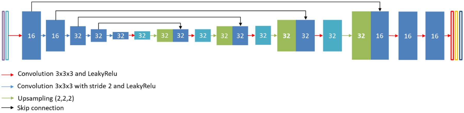
The detailed structure for the U-net core (Fig. 1). The input has two channels: the source image and the FDK-reconstructed target image from the cone-beam projections. The output has three channels, each representing DVFs along one Cartesian directions (x, y, and z). The number on each block indicates the number of filters.
II.A.3. DVF Inversion layer:
The U-net core structure outputs the forward DVF that maps the source image to the target image. Contrary to the forward DVF, inverse DVF maps the target image back to the source image. The simultaneous solution of the inverse DVF along with the forward DVF is desired for many applications, including motion-compensated reconstruction and finite-element-analysis based biomechanical modeling (Wang and Gu, 2013; Zhang et al., 2016b; Biguri et al., 2017). The solution of inverse-consistent DVF pairs also further regularizes and improves the DVF accuracy. The inverse DVF was usually computed as the negate of the forward DVF, which was also employed in previous 2D-3D deformable registration algorithms (Wang and Gu, 2013). However, it is acknowledged that the negate operation is over-simplified and can lead to large inversion errors especially for those regions with large deformations (Chen et al., 2008). For previously developed 2D-3D algorithms, more complex DVF inversion schemes like the fixed-point iterative method and the Newton’s method was not used as they would render the gradient difficult to be analytically computed to drive DVF optimization (Gobbi and Peters, 2003; Chen et al., 2008). With the automatic differentiation method employed in deep learning network for gradient calculation and parameter optimization, however, more advanced inversion schemes can potentially be incorporated into the network. In this study, we incorporated a DVF inversion layer based on the iterative fixed-point method to generate the inverse DVFs based on their forward counterparts (Chen et al., 2008).
II.A.4. Forward-projection layer:
To compute the similarity metric in the 2D projection domain, a GPU-enabled, non-trainable forward-projection layer was incorporated as a network layer, which computes 2D cone-beam projections from the deformed images using the Siddon’s ray-tracing algorithm (Siddon, 1985a; Syben et al., 2019a). The conjugate filtered back-projection operation (FDK) was registered as the gradient of the network layer when back-propagating the gradient of the designed network. Both the forward-projection layer and back-projection FDK reconstruction layer were adapted from the PYRO-NN (python reconstruction operators in neural networks) package (Syben et al., 2019b), which provides them as embedded known operators that preserve the domain knowledge in image reconstruction while allowing an end-to-end deep learning chain using the Tensorflow backend (Abadi et al., 2016).
II.B. Loss function design
In 2D3D-RegNet, we defined three different loss functions to train the network. The 1st loss term (Loss1) measures the similarity between the input 2D cone-beam projections and the DRRs projected from the deformed source image (Equation set 1, Fig. 1). It serves as the main data fidelity term to drive the optimization of the DVF (v).
| (1) |
In Equation set 1, Isource indicates the source image to be deformed (the fully-sampled 3D prior image, as in the case of 2D-3D deformable registration). x indicates the Cartesian coordinates of the Isource voxels, and v indicates the corresponding DVF at each voxel coordinate. Idef represents the resulting deformed source image, which was mapped by trilinear interpolation in this study (Ren et al., 2012). Ptarget indicates the on-board acquired target 2D projections reflecting the most up-to-date patient anatomical information, which drives the 2D-3D deformable registration. A is the system matrix that maps Idef onto the Ptarget reference frame using the Siddon’s ray-tracing algorithm (Siddon, 1985b). D indicates the image similarity metric, which can take many forms including mean absolute error, mean squared error, cross correlation, or mutual information (Viola and Wells III, 1997; Willmott and Matsuura, 2005; Zhao et al., 2006; Wang and Bovik, 2009). In this study, we used mean squared error as the similarity metric, while more advanced metrics may be used to improve the registration robustness.
The 2nd loss term (Loss2) employed in the network is the inverse similarity loss, based on the inverse DVF generated from the DVF inversion layer (II.A.3) (Zhang et al., 2016b). In the DVF inversion layer, the inverse DVF (vinv) was calculated via an iterative fixed-point conversion scheme as (Chen et al., 2008):
| (2) |
n indicates the iteration number, with its maximum N. To strike a balance between the computational/memory load and accuracy, we set N = 7 in this study. vinv yields the corresponding Loss2 as shown in Equation set 3:
| (3) |
This loss term serves to measure the similarity between the inversely-deformed Iinv−def and the original Isource, enforcing the inverse-consistency of the DVF. Since a 3D high-quality target image is not available for inverse registration, except for the low-quality one reconstructed from the Ptarget projections, we used the forwardly-deformed source image Idef as the target image to feed into the inverse-deformation scheme to generate the inversely-deformed Iinv-def (Equation set 3). The forward-projection layer applied system matrix A to Iinv-def to generate DRRs for comparison with DRRs simulated directly from Isource. Same as Loss1, Loss2 was designed to measure the similarity metric D along the projection domain. Such a design eliminates the necessity of applying a relative weighting factor between Loss1 and Loss2 which is needed if they are measuring similarities at different image domains. In general, the Loss2 term not only helps to further regularize the DVF solution, but also offers an inverse DVF to drive advanced applications like biomechanical modeling and motion-compensated reconstruction (Wang and Gu, 2013; Zhang et al., 2016b).
The 3rd loss term (Loss3) for the network training calculates the DVF energy and enforces the DVF smoothness:
| (4) |
In Equation 4, m indicates one of the three Cartesian directions x, y and z. vm indicates the DVF along the corresponding m direction. ni, nj and nk indicate the image dimension along the three Cartesian directions x, y and z, respectively. DVF energy regularization is commonly applied in deformable registration algorithms to help preserve the smoothness of the deformation field, and reduce the solution space for more stable convergence (Lu et al., 2004). A weighting factor of 5 was applied to the energy term relative to the combined Loss1 and Loss2 terms after trial-and-error, to balance the data fidelity and the regularization loss terms.
II.C. Data preparation and training scheme:
To train the 2D3D-RegNet, we used 4D-CT lung datasets from two public libraries: the cancer imaging archive (TCIA) (Hugo et al., 2016) and the CREATIS laboratory (Vandemeulebroucke et al., 2011). A total of 20 4D-CT sets from TCIA, and another 6 4D-CT sets from CREATIS were used as our training dataset. Each 4D-CT set has a total of 10 respiratory phase volumes. All 4D-CT phase volumes were resampled to 256 × 256 × 256 in size, with each voxel measuring 1.5 mm × 1.5 mm × 1.5 mm in dimension. For each 4D-CT set, we extracted the end-expiration phase as the 3D source image, and simulated 2D cone-beam projections from all phases (including the end-expiration phase) for 2D-3D registration. The projection matrix was simulated in full-fan mode with 512 × 512 pixels, with each pixel measuring 0.8 mm × 0.8 mm in dimension to match the X-ray volume imaging (XVI) system of Elekta (Elekta Limited: Crawley, UK) (Thing et al., 2013). For the cone-beam geometry, the source-to-isocenter distance was 1000 mm and the source-to-detector distance was 1500 mm. The projections were simulated to match two limited-angle acquisition scenarios (Fig. 3): (1). Single-view: projections evenly distributed over a single-angle spanning around the anterior-posterior (AP) direction of the patient; and (2). Ortho-view: projections evenly distributed over two orthogonally-arranged angle spans, one along the AP direction, and the other along the left lateral direction of the patient. For each scenario, five total scan angle spans were simulated: 0°, 15°, 30°, 60° and 90°. The projections at each cluster were sampled every 1°.
Figure 3.
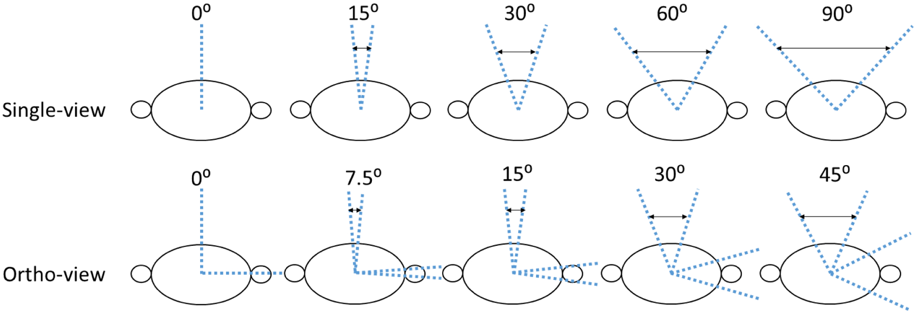
The two simulated limited-angle projection acquisition scenarios: (1). The 1st row shows the single-view acquisition scenarios with scan angles spanning from 0° to 90° around the anterior-posterior (AP) direction. (2). The 2nd row shows the ortho-view acquisition scenarios with scan angles evenly split around the AP and left lateral directions. The projections at each cluster were sampled every 1°.
The 2D3D-RegNet was developed through the Keras application programming interface (Version 2.3.0) (Gulli and Pal, 2017), using Tensorflow (Version 2.2.0) as the backend (Abadi et al., 2016). For training of the 2D3D-RegNet, we used a batch size of 1 due to the GPU card memory limit. Each batch randomly selected one patient from the 26 data sets, extracted the end-expiration phase as the source image, and randomly selected the simulated cone-beam projections at one phase as the new cone-beam projections. The 2D projections and the 3D source images were simultaneously input into the 2D3D-RegNet (Fig. 1) to drive the unsupervised, end-to-end, 2D-3D deformable registration training. A total of 50000 epochs were used to train 2D3D-RegNet, which took ~72 hours on a NVIDIA V100 GPU card (NVIDIA Corporation, Santa Clara, CA). Independent models were developed and trained for each of the angular acquisition scenarios shown in Fig. 3.
II.D. Testing and evaluation:
II.D.1. Testing data:
We used an independent in-house 4D-CT lung dataset to test the efficacy of the developed 2D3D-RegNet. The corresponding dataset has 12 lung patient cases, and each case has 10–14 respiratory phase volumes. Similar to the training dataset, the image volumes were resized to 256 × 256 × 256 with each voxel measuring 1.5 mm × 1.5 mm × 1.5 mm in dimension. The end-expiration phase of each case was selected as the source image, and cone-beam projections were simulated from the end-inspiration phase volume according to the scan angle scenarios of Fig. 3. The end-inspiration phase was used for testing as it has the largest extent of deformation from the source image, and could better assess the accuracy of 2D3D-RegNet.
II.D.2. Evaluation metrics:
The images deformed using 2D3D-RegNet were visually compared against the original end-inspiration CT phase volumes which were used as the ‘ground-truth’ (IGT). Relative errors (REs) were calculated between the deformed and ‘ground-truth’ images to quantitatively assess the deformation accuracy (Eq. 5).
| (5) |
The RE metric calculates the attenuation coefficient difference between Idef and IGT. A larger RE indicates more deviation from the true image.
Besides the images, 952 lung landmarks of small lung details were manually tracked by expert physicians on the 4D-CT lung dataset, which were also used as the reference to benchmark the DVFs solved by 2D3D-RegNet (Werner et al., 2009; Zhang et al., 2016b). The target registration error (TRE) was defined as:
| (6) |
indicates the tracked landmark motion along direction m.
II.D.3. Evaluation scheme:
To evaluate the efficiency and accuracy of 2D3D-RegNet in the context of currently available methods, we compared the deformation accuracy of 2D3D-RegNet against that of the traditional iterative 2D-3D registration algorithm (Zhang et al., 2016b), and a widely-utilized 3D-3D deformable registration open-source package (Elastix) (Klein et al., 2009). Same as 2D3D-RegNet, the iterative 2D-3D registration algorithm combines symmetric forward and inverse data fidelity terms to enforce 2D projection matching, and an energy term for DVF regularization (Zhang et al., 2016b). The gradient of the overall objective function can be analytically derived to implement gradient-based optimization algorithms, and the conjugate gradient algorithm was used in this study. More details regarding the traditional 2D-3D deformable registration algorithm can be found in previous publications (Zhang et al., 2013b; Zhang et al., 2016b). On the other hand, Elastix is a popular 3D-3D deformable registration package which found wide applications in a number of studies (Staring et al., 2010; Kerner et al., 2015; Marchant et al., 2018). To use Elastix for registration, we reconstructed the 2D projections to a 3D target volume (Feldkamp et al., 1984), and performed registrations between the source and the reconstructed target 3D volumes.
In actual clinical scenarios, the angular sampling frequency may differ from the 1°/projection setting adopted in our network training process. To further evaluate the robustness of 2D3D-RegNet, we differed the angular sampling frequency during the test time, and evaluated how it affected the registration accuracy. Five additional scenarios were simulated: (a). 0.25°/projection, (b). 0.5°/projection, (c). 2°/projection, (d). 4°/projection, and (e). 8°/projection. In addition to angular sampling frequency variations, the scan angles may also not conform exactly to what was adopted during training (Fig. 3). Thus we also evaluated scenarios in test time where the scan angles deviated from those in training by five different magnitudes: (a). off by 5°, (b). off by 10°, (c). off by 15°, (d). off by 20°, and (e). off by 25°. The impacts of these variations in test time were quantified and analyzed through the metrics defined in II.D.2.
Since 2D-3D deformable registration (based on limited-angle projections) is an ill-conditioned problem, previous studies also combined different DVF fine-tuning steps to further improve the accuracy of solved DVFs (Zhang et al., 2013b; Zhang et al., 2016b). In this study, we also added a biomechanical modeling step after 2D3D-RegNet to demonstrate that 2D3D-RegNet can function as a core to generate DVFs in near real-time, and the output DVFs could then be fine-tuned by far less computationally-expensive steps for efficient and high-quality deformable registration (Fig. 4). In general, the biomechanical modeling step uses the 2D3D-RegNet solved DVFs at the organ of interest boundary (lung in this study) to provide boundary condition to drive finite-element-analysis based lung DVF correction. The physics-driven biomechanical modeling step helps to correct the residual errors of the pure intensity-driven DVFs solved by 2D3D-RegNet, especially those around small fine structures or low-contrast regions (Zhang et al., 2016b; Zhang et al., 2019). For biomechanical modeling, a lung mesh of tetrahedral elements needs to be built from the lung contour segmentation of the source image, which could be conveniently generated off-line as soon as the source image becomes available. More details about the biomechanical modeling process, including the mathematical derivations, the material models used, and the corresponding elasticity parameter optimization can be found in our previous publication (Zhang et al., 2016b).
Figure 4.
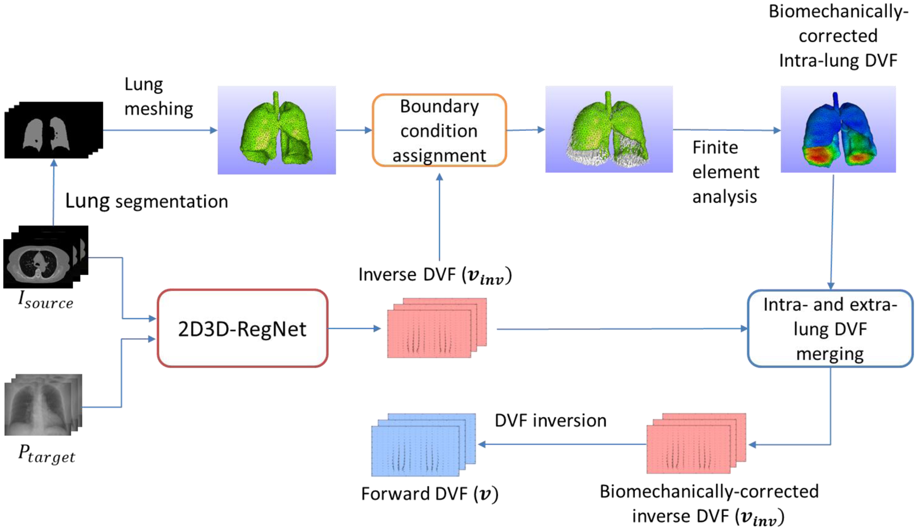
The synergistic scheme of 2D3D-RegNet and biomechanical modeling. The 2D3D-RegNet outputs the inverse DVF(vinv) for biomechanical modeling-based correction, and the biomechanically-corrected inverse DVF is inverted in the end to forward DVF (v) which deforms the source image (Isource) to the target image.
In clinical scenarios, the source and the target images may be acquired hours, days or weeks apart, and may contain motion/deformation patterns not seen between same-session 4D-CT images (intra-scan). For more comprehensive evaluation, we included additional 4D-CT image sets (inter-scan) from the TCIA library. Out of the 20 patient cases of the library, 14 of them have inter-scan 4D-CT sets that are acquired weeks apart from the original 4D-CT set which we used in II.C. We included these inter-scan 4D-CT sets of 10 cases into the training set which was described in II.C, and tested the trained model on the inter-scan 4D-CT sets of the other 4 cases. To perform the inter-scan registration, we used the same end-expiration phase volume of the original 4D-CT set (II.C) as the 3D source image, and simulated the cone-beam projections from all the inter-scan 4D-CT phase volumes. In total, an additional 310 images were added to the training dataset, and a total of 160 inter-scan images were used for testing (a few inter-scan 4D-CT images of the TCIA dataset were excluded, due to substantial differences between their covered range in the longitudinal direction and that of the original 4D-CT set). Prior to the deformable registration, the source images were rigidly-registered to the inter-scan target projections to roughly align their positioning (Zhang et al., 2013a). The RE metric between the deformed and the ‘ground-truth’ inter-scan images was calculated for quantitative analysis.
III. Results:
III.A. Image Comparison
As shown in Figs. 5 (a) and 5 (b), the limited-angle projections from a single-view yielded significant artifacts and structure distortions in the reconstructed FDK images (Target-FDK). Correspondingly, direct 3D-3D deformable registration by Elastix is error-prone, which generated severe distortions in the deformed images (Elastix). For the Elastix registration results shown in Fig. 5, we used a region-of-interest mask to exclude regions outside the imaging field-of-view to account for the limited projection size, which however is unable to suppress the strong distortion artifacts from limited-angle sampling. In comparison, 2D3D-RegNet has preserved the image integrity and did not introduce the distortions into the deformed image (2D3D-RegNet). It also deformed the lungs to well match with the ground-truth target images (Target-GT). When ortho-view projections were used (Figs. 5 (c) and 5 (d)), the image distortion artifacts were mitigated in the FDK images, which however still severely impacted the accuracy of Elastix-based deformable registration. The 2D3D-RegNet, on the other hand, worked well in both single-view and ortho-view projection scan angle scenarios.
Figure 5.
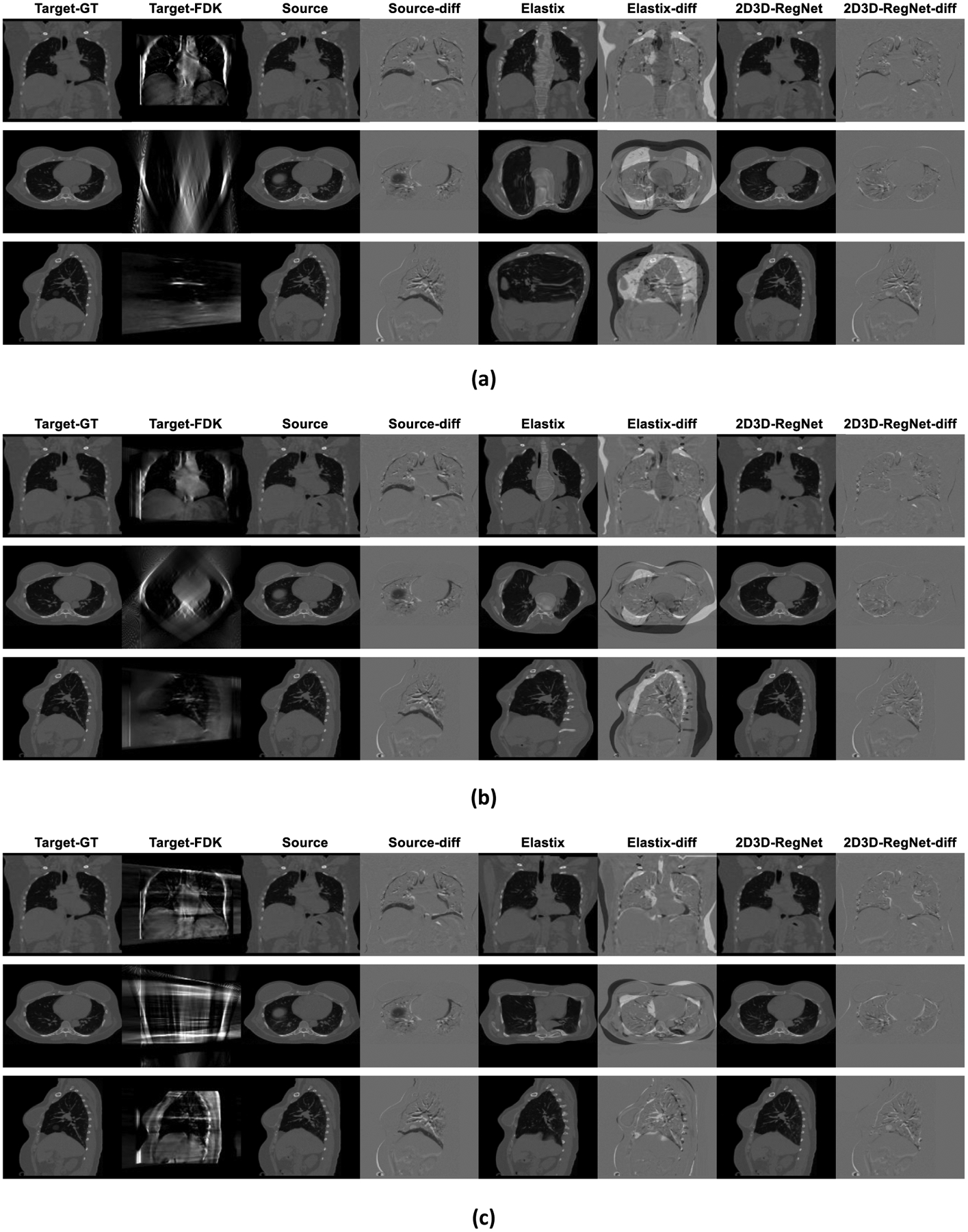
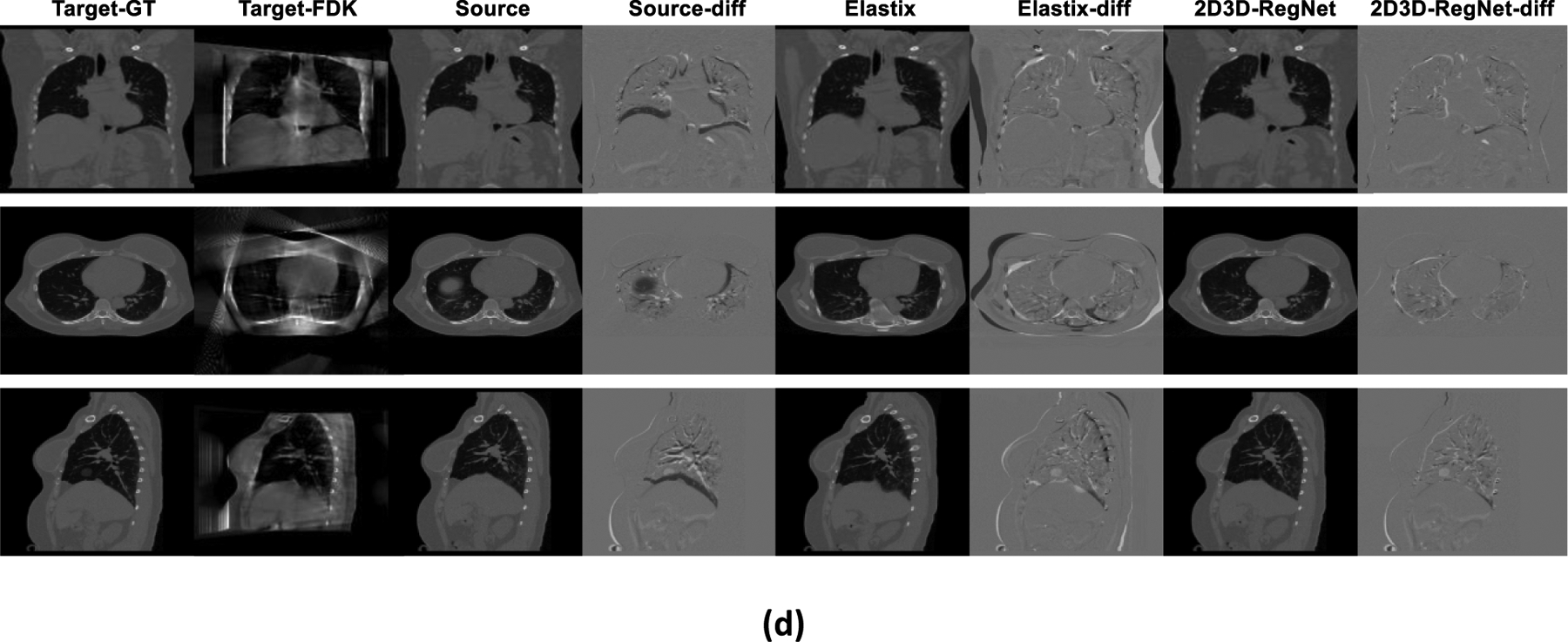
Three-view image comparison for one patient case (intra-scan), between ‘ground-truth’ target images (Target-GT), FDK-reconstructed target images (Target-FDK) by limited-angle projections, source images (Source) before deformable registration, difference images (Source-diff) between Source and Target-GT, Elastix-deformed images (Elastix) with deformation between Source and Target-FDK, difference images (Elastix-diff) between Elastix and Target-GT, and 2D3D-RegNet-deformed images (2D3D-RegNet), and difference images (2D3D-RegNet-diff) between 2D3D-RegNet and Target-GT. Four sub-figures were presented based on different scan angle scenarios (Fig. 3): (a). 30° scan angle (single-view), (b). 90° scan angle (single-view), (c). 30° scan angle (ortho-view, 15° each), and (d). 90° scan angle (ortho-view, 45° each). The angular sampling frequency was 1°/projection for all four scenarios.
III.B. Quantitative Evaluation
Quantitative results shown in Table 1 and Table 2 echoed the images presented in Fig. 5. The 2D3D-RegNet substantially improved the accuracy of the estimated on-board CBCT images through the deformation-driven approach, as compared to that of the CBCT images directly reconstructed by the FDK algorithm (Table 1). The 2D3D-RegNet also outperformed the Elastix (with and without masks) in terms of the accuracy of the deformed images and the accuracy of the DVFs (Table 1 and Table 2). Increasing the scan angle expectedly improves the accuracy of 2D3D-RegNet. Though with the same total scan angles, projections acquired from an orthogonal-view setting yielded better results than those acquired from a single direction, due to the complimentary information offered from the orthogonal directions. Comparing the traditional 2D-3D deformable registration with 2D3D-RegNet, under the single-view scan angles their results are similar (2D3D-RegNet performed better on the TRE metric), while under the orthogonal-view scan angles the traditional 2D-3D deformable registration algorithm performed better in the RE metric. Speed-wise, the 2D3D-RegNet solved DVFs for image volumes of size 256 × 256 × 256 in < 5 seconds at test time. In comparison, the iterative 2D-3D registration technique takes ~1.5 hours for 30 projections, and 4–5 hours for 90 projections. Even though GPU-acceleration has already been incorporated into the iterative 2D-3D deformable registration technique, the conjugate gradient algorithm employed in its optimization scheme is very computationally expensive and time consuming in the step size searching process (Ren et al., 2012), which rendered the overall computation time prohibitively long.
Table 1.
Comparison between the relative errors (REs) of images generated by different methods, using different scan angle schemes. For Elastix, the mask is defined as a region-of-interest (ROI) equal to the limited imaging field-of-view, as determined by the limited projection size (512 × 512 pixels, with 0.8 mm × 0.8 mm each pixel) which is unable to cover the full patient volume. FDK: Feldkamp-Davis-Kress (reconstruction algorithm). Def: deformation.
| RE/% | Scan angle schemes | FDK | Elastix w/o mask for def* | Elastix w/mask for def | 2D-3D def | 2D3D-RegNet |
|---|---|---|---|---|---|---|
| single-view | 0° | 155.3 ± 20.0 | 60.8 ± 9.8 | 53.7 ± 8.9 | 21.3 ± 3.4 | 20.4 ± 3.0 |
| 15° | 113.0 ± 15.2 | 60.4 ± 10.3 | 53.4 ± 8.7 | 19.6 ± 3.1 | 18.2 ± 2.8 | |
| 30° | 95.3 ± 12.9 | 59.3 ± 10.9 | 53.5 ± 9.9 | 18.1 ± 2.9 | 17.7 ± 2.8 | |
| 60° | 72.5 ± 8.5 | 57.2 ± 11.1 | 44.6 ± 8.5 | 15.5 ± 2.5 | 16.1 ± 2.5 | |
| 90° | 57.1 ± 5.7 | 48.3 ± 9.6 | 41.0 ± 7.9 | 15.0 ± 2.8 | 15.3 ± 2.4 | |
| ortho-view | 0° (0° each) | 133.2 ± 19.0 | 38.9 ± 5.6 | 36.8 ± 5.1 | 17.8 ± 2.7 | 19.2 ± 2.4 |
| 15° (7.5° each) | 105.3 ± 15.6 | 38.4 ± 5.7 | 36.3 ± 5.4 | 13.8 ± 2.5 | 16.3 ± 2.8 | |
| 30° (15° each) | 90.3 ± 13.1 | 36.7 ± 4.3 | 34.1 ± 5.4 | 12.4 ± 2.1 | 15.4 ± 2.5 | |
| 60° (30° each) | 67.8 ± 10.6 | 33.4 ± 4.9 | 29.3 ± 4.9 | 11.2 ± 1.6 | 14.8 ± 2.4 | |
| 90° (45° each) | 52.0 ± 9.9 | 29.3 ± 4.6 | 24.3 ± 4.6 | 11.1 ± 1.5 | 14.4 ± 2.1 |
Table 2.
Comparison between the target registration errors (TREs) for deformation vector fields (DVFs) generated by different methods, using different scan angle schemes. For Elastix, the mask is defined as a region-of-interest (ROI) equal to the limited imaging field-of-view, as determined by the limited projection size (512 × 512 pixels, with 0.8 mm × 0.8 mm each pixel) which is unable to cover the full patient volume. Note for both Elastix registration results (with and without mask), we calculated TRE only within the ROI defined by the mask, to avoid accounting the DVF errors caused by the field-of-view issue. FDK: feldkamp-Davis-Kress (reconstruction algorithm). Def: deformation.
| TRE/mm | Scan angle schemes | Elastix w/o mask for def | Elastix w/mask for def | 2D-3D Def | 2D3D-RegNet |
|---|---|---|---|---|---|
| single-view | 0° | 31.6 ± 22.5 | 28.4 ± 17.7 | 6.4 ± 4.7 | 5.4 ± 4.1 |
| 15° | 30.0 ± 21.6 | 29.3 ± 18.2 | 5.5 ± 4.1 | 4.8 ± 3.5 | |
| 30° | 25.8 ± 17.6 | 25.0 ± 16.8 | 5.2 ± 4.0 | 4.6 ± 3.5 | |
| 60° | 21.2 ± 15.8 | 14.0 ± 9.3 | 4.6 ± 3.7 | 4.3 ± 3.4 | |
| 90° | 12.6 ± 8.2 | 7.0 ± 5.3 | 5.0 ± 3.9 | 4.3 ± 3.3 | |
| ortho-view | 0° (0° each) | 10.5 ± 6.8 | 9.4 ± 6.0 | 6.0 ± 4.4 | 5.4 ± 3.7 |
| 15° (7.5° each) | 10.7 ± 6.6 | 9.5 ± 6.2 | 4.7 ± 3.5 | 4.8 ± 3.4 | |
| 30° (15° each) | 11.0 ± 6.8 | 8.8 ± 6.2 | 4.3 ± 3.4 | 4.5 ± 3.4 | |
| 60° (30° each) | 10.3 ± 6.8 | 7.3 ± 5.8 | 4.0 ± 3.3 | 4.1 ± 3.1 | |
| 90° (45° each) | 8.5 ± 7.0 | 5.4 ± 4.6 | 3.8 ± 3.1 | 3.9 ± 3.0 |
III.C. Preliminary robustness analysis of 2D3D-RegNet
Table 3 summarizes the accuracy of the deformed images and the DVFs solved by 2D3D-RegNet, under testing scenarios where the projection angular sampling frequencies differed from that used in training. The overall impact of angular sampling frequency variations is small. When angular sampling frequency changed from 0.25°/prj to 8°/prj, the average RE changed 0.3% - 0.8%, and the average TRE changed less than 0.3 mm. The 2D3D-RegNet demonstrated robustness towards angular sampling frequency variations, indicating the same network can potentially be applied to clinical scenarios with different angular sampling frequencies.
Table 3.
Comparison between the relative errors (REs) and target registration errors (TREs) for images and deformation vector fields (DVFs) solved by 2D3D-RegNet, using different angular sampling frequencies at test time. Four scan angle scenarios were included in this evaluation: single-view 30°, ortho-view 30°, single-view 90° and ortho-view 90° (Fig. 3). The networks were separately trained on the four scan angle scenarios, under the 1°/projection (prj) angular sampling frequency. During testing, the angular sampling frequencies were varied from 0.25°/prj to 8°/prj.
| 0.25°/prj | 0.5°/prj | 1°/prj | 2°/prj | 4°/prj | 8°/prj | ||
|---|---|---|---|---|---|---|---|
| 30° (Single-view) | RE/% | 17.7 ± 2.8 | 17.7 ± 2.8 | 17.7 ± 2.8 | 17.7 ± 2.8 | 17.7 ± 2.8 | 18.0 ± 2.8 |
| TRE/mm | 4.6 ± 3.5 | 4.6 ± 3.5 | 4.6 ± 3.5 | 4.6 ± 3.5 | 4.6 ± 3.5 | 4.7 ± 3.6 | |
| 30° (Ortho-view, 15° each) | RE/% | 15.4 ± 2.5 | 15.4 ± 2.5 | 15.4 ± 2.5 | 15.4 ± 2.5 | 15.7 ± 2.6 | 16.2 ± 2.8 |
| TRE/mm | 4.5 ± 3.4 | 4.5 ± 3.4 | 4.5 ± 3.4 | 4.5 ± 3.5 | 4.6 ± 3.5 | 4.8 ± 3.6 | |
| 90° (Single-view) | RE/% | 15.3 ± 2.4 | 15.3 ± 2.4 | 15.3 ± 2.4 | 15.3 ± 2.4 | 15.4 ± 2.3 | 15.7 ± 2.3 |
| TRE/mm | 4.3 ± 3.3 | 4.3 ± 3.3 | 4.3 ± 3.3 | 4.3 ± 3.3 | 4.3 ± 3.3 | 4.3 ± 3.3 | |
| 90° (Ortho-view, 45° each) | RE/% | 14.4 ± 2.1 | 14.4 ± 2.1 | 14.4 ± 2.1 | 14.4 ± 2.1 | 14.5 ± 2.2 | 15.0 ± 2.3 |
| TRE/mm | 3.9 ± 3.0 | 3.9 ± 3.0 | 3.9 ± 3.0 | 3.9 ± 3.0 | 3.9 ± 3.0 | 4.0 ± 3.1 |
Similar to Table 3, Table 4 summarizes the accuracy of the deformed images and the DVFs solved by 2D3D-RegNet, under testing scenarios where the overall scan angles were offset by various degrees, as compared to the training scenario (Fig. 3). Compared to angular sampling frequency variation, the 2D3D-RegNet was not as robust to scan angle offset. However, scan angle offsets up to 15° yielded RE changes within 1%, and TRE changes within 0.2 mm, for the four scan angle scenarios studied. Acquisitions of smaller scan angles were more susceptible to the scan angle offset, which is expected.
Table 4.
Comparison between the relative errors (REs) and target registration errors (TREs) for images and deformation vector fields (DVFs) solved by 2D3D-RegNet, using different offset angles at test time. Four scan angle scenarios were included in this evaluation: single-view 30°, ortho-view 30°, single-view 90° and ortho-view 90° (Fig. 3). The networks were separately trained on the four scan angle scenarios, with angle directions specified in Fig. 3. During testing, the scan angles were collectively offset by magnitudes ranging from 0° to 25°.
| off 0° | off 5° | off 10° | off 15° | off 20° | off 25° | ||
|---|---|---|---|---|---|---|---|
| 30° (Single-view) | RE/% | 17.7 ± 2.8 | 17.7 ± 2.8 | 18.0 ± 2.8 | 18.4 ± 2.9 | 18.8 ± 2.9 | 19.4 ± 3.0 |
| TRE/mm | 4.6 ± 3.5 | 4.6 ± 3.5 | 4.7 ± 3.6 | 4.8 ± 3.8 | 5.0 ± 3.9 | 5.2 ± 4.1 | |
| 30° (Ortho-view, 15° each) | RE/% | 15.4 ± 2.5 | 15.6 ± 2.4 | 15.9 ± 2.5 | 16.2 ± 2.5 | 16.8 ± 2.6 | 17.2 ± 2.6 |
| TRE/mm | 4.5 ± 3.4 | 4.5 ± 3.4 | 4.6 ± 3.5 | 4.6 ± 3.6 | 4.7 ± 3.7 | 4.8 ± 3.8 | |
| 90° (Single-view) | RE/% | 15.3 ± 2.4 | 15.4 ± 2.4 | 15.7 ± 2.4 | 16.0 ± 2.4 | 16.3 ± 2.5 | 16.6 ± 2.5 |
| TRE/mm | 4.3 ± 3.3 | 4.3 ± 3.4 | 4.4 ± 3.4 | 4.5 ± 3.5 | 4.6 ± 3.6 | 4.7 ± 3.8 | |
| 90° (Ortho-view, 45° each) | RE/% | 14.4 ± 2.1 | 14.3 ± 2.1 | 14.4 ± 2.1 | 14.5 ± 2.2 | 14.8 ± 2.2 | 15.2 ± 2.3 |
| TRE/mm | 3.9 ± 3.0 | 3.9 ± 3.0 | 4.0 ± 3.0 | 4.0 ± 3.1 | 4.0 ± 3.1 | 4.1 ± 3.1 |
III.D. 2D3D-RegNet and biomechanical modeling synergy
The original TRE between the source and target images with zero DVFs for all 952 landmarks is 6.7 ± 5.2 mm. Based on a scan angle of ortho-view 30°, the mean (± s.d.) TRE reduced to 4.5 ± 3.4 mm by 2D3D-RegNet. Incorporating additional biomechanical modeling (Fig. 4) further reduced the TRE to 3.7 ± 2.8 mm. Increasing the scan angle to ortho-view 90° further reduced the TRE to 3.3 ± 2.4 mm, for 2D3D-RegNet with biomechanical modeling fine-tuning. The registration results of ortho-view 90° were similar to a previous biomechanical modeling study based on the same data (3.3 ± 2.1 mm) (Werner et al., 2009). This previous study, however, used boundary conditions derived through direct registrations between the original fully-sampled 3D images. Using only ortho-view 90° projections (45° from each direction), 2D3D-RegNet was able to generate similarly accurate boundary conditions to drive finite element analysis for biomechanical modeling. A previous publication combining traditional iterative 2D-3D registration and biomechanical modeling generated slightly better results (2.9 ± 2.1 mm) (Zhang et al., 2016b). This previous study, however, used sparse projections covering a full 360° scan angle, and based on a much larger projection size (300 × 200, with 2 mm × 2 mm per pixel) that covers the full field-of-view. In addition, the previous study requires a computation time of over 1 hour for 20 projections. In comparison, the combined 2D3D-RegNet and biomechanical modeling runtime is less than 1 minute, which renders the total registration timeframe clinically feasible.
III.E. Evaluation of inter-scan registration
As shown in Fig. 7, for inter-scan registration, 2D3D-RegNet not only registered the respiratory-induced deformation (for instance, around the diaphragm region), but also registered mismatched areas including the upper chest wall where the image difference is more correlated with inter-scan positioning variation. The inter-scan external body contour mismatch has also been partially corrected by 2D3D-RegNet, especially for the ortho-90° scan angle scenario. Due to the field-of-view limit, some mismatches remain, especially for the single-90° scenario where the structure distortions in the FDK images were more severe.
Figure 7.
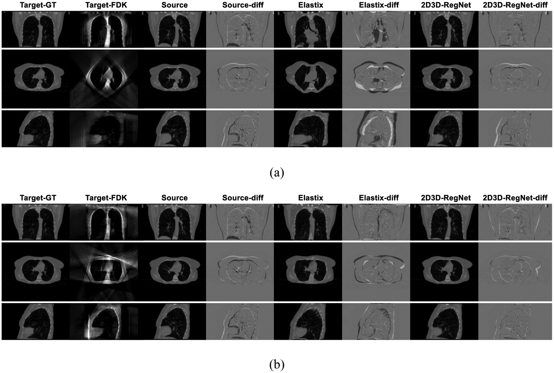
Three-view image comparison for one patient case (inter-scan), between ‘ground-truth’ target images (Target-GT), FDK-reconstructed target images (Target-FDK) by limited-angle projections, source images (Source) before deformable registration, difference images (Source-diff) between Source and Target-GT, Elastix-deformed images (Elastix) with deformation between Source and Target-FDK, difference images (Elastix-diff) between Elastix and Target-GT, and 2D3D-RegNet-deformed images (2D3D-RegNet), and difference images (2D3D-RegNet-diff) between 2D3D-RegNet and Target-GT. Two sub-figures were presented based on different scan angle scenarios (Fig. 3): (a). 90° scan angle (single-view), and (b). 90° scan angle (ortho-view, 45° each). The angular sampling frequency was 1°/projection for both scenarios.
Quantitatively, using single-90° projections for reconstruction/registration, the average (± s.d.) REs of Target-FDK, Elastix (with field-of-view mask) and 2D3D-RegNet were 55.4% (± 1.8%), 37.4% (± 5.0%), and 19.2% (± 4.1%), respectively. For ortho-90° projections, the corresponding results were 52.0% (± 2.6%), 28.6% (± 2.7%), and 17.3% (± 3.5%). The 2D3D-RegNet presented larger REs as compared to the intra-scan registration evaluation (Table 1 and Table 2), which is expected as the deformation/motion patterns became more diverse and complex between inter-scan images to learn and register.
IV. Discussion:
2D-3D deformable registration is a promising technique that can generate high-quality, accurate on-board CBCT images from prior images and sparse-view or limited-angle on-board projections. The mapping of prior information to new CBCT using DVFs can not only save on-board imaging dose/time, but enables accurate Hounsfield unit (HU) rendering for on-board dose calculation/optimization (Zhang et al., 2015b). The solved DVFs also fit well into the adaptive radiotherapy workflow to enable contour propagation and dose accumulation (Yan et al., 1997). To address the speed bottleneck of current iterative 2D-3D deformable registration techniques, in this study we developed an end-to-end, unsupervised 2D-3D deformable registration network frame to allow near real-time DVF solution. Visual comparisons of the deformed images (Fig. 5, Fig. 7), and corresponding quantitative evaluations of these images and the solved DVFs (Table 1, Table 2), demonstrated the superiority of 2D3D-RegNet over the conventional FDK reconstruction algorithm, and a 3D-3D registration method (Elastix). In the current 2D3D-RegNet structure, we reconstructed the 2D projections at the beginning to a 3D volume via FDK to align with the source 3D image, such that both can be conveniently fed into a subsequent U-net core as parallel channels. The FDK reconstruction is a degenerative process, especially considering the 2D projections are limited-angle, which leads to severe under-sampling artifacts in the reconstructed images (Fig. 5, Fig. 7). However, since the image similarity metric is measured by 2D3D-RegNet on re-projected 2D DRRs of the deformed image, instead of directly on artifact-ridden 3D images, the final deformation results are superior to direct 3D image-domain registration, with artifacts and distortions successfully suppressed (Fig. 5, Fig. 7 Table 1 and Table 2). Although the current study is based on limited-angle projections, the same network is readily applicable to sparse-view projections, where a few acquired projections cover a full scan-angle.
The results also showed that 2D3D-RegNet performed similarly to the traditional iterative 2D-3D registration algorithm (Table 2), while with substantially improved efficiency (< 5 seconds as compared to hours). However, the iterative 2D-3D registration algorithm generated comparatively smaller REs than 2D3D-RegNet (Table 1) under ortho-view scan angles. The discrepancy is potentially due to the artifacts and the distortions presented in the FDK input channel when the projections from two distinct, orthogonally-arranged scan angles were mixed together in reconstruction, as well as the loss of information from the degenerative FDK reconstruction process (Fig. 5, Fig. 7). Potential solutions to further improve the accuracy of 2D3D-RegNet include adding additional image filtration or enhancement layers after the FDK reconstruction module, or directly inputting the 2D projections into the network without explicit reconstruction, or feeding the projections into the network multiple times through a recurrent or cascaded pattern. Inputting two FDK channels separately reconstructed from the projections at each orthogonal direction, instead of one channel reconstructed from the mixed projections, may also be helpful.
In this study, we preliminarily evaluated the robustness of 2D3D-RegNet towards projection angular sampling frequency variations and scan angle variations (Table 3 and Table 4). Such a test is clinically relevant, considering actual clinical projection acquisitions can be similarly prone to these variations. The developed 2D3D-RegNet showed robustness to the variations of angular sampling frequency (Table 3), while being less robust to large scan angle offsets (Table 4). For the latter scenario, training a couple of models with different scan angle variations can help to select the most appropriate one during test time. A model trained using inputs of various scan angle scenarios may also help to improve its robustness to scan angle variations, which remains to be investigated in future studies.
In general, the 2D3D-RegNet performed well for inter-scan registration, as demonstrated in Fig. 7 and the corresponding RE results. To roughly align the source image to the target volume to account for their inter-scan positioning differences, we performed a rigid-registration between the source images and the inter-scan target projections based on a previously published method (Zhang et al., 2013a), prior to feeding them into deformable registration. In addition, other machine/deep learning-based 2D-3D rigid registration methods may also be combined with 2D3D-RegNet for fast initial rigid alignment (Ouadah et al., 2017; Shun et al., 2016). In radiotherapy treatments, pre-treatment setup scans are usually performed for alignment/verification. If the pre-treatment scan is used as the source image for intra-fractional 2D-3D deformable registration, the rigid registration may not be needed. Otherwise, if another source image is used, it can be rigidly-registered to this pre-treatment scan in 3D to eliminate large positioning differences prior to deformable registration. After initial rigid alignment between source and target images, 2D3D-RegNet is able to correct the residual mismatches including remaining positioning variations and deformation.
We simulated the cone-beam projections using the ray-tracing technique in this study from ‘ground-truth’ CT volumes, such that quantitative evaluations on the deformed volumes can be performed using the known ‘ground-truth’. The projections were simulated to match with actual projection sizes offered by the Elekta XVI system. The limited field-of-view resulted from the realistically-simulated projection sizes led to inaccurate registrations at peripheral regions for the 3D-3D registration technique, which however had a much smaller impact on the 2D3D-RegNet results (Fig. 5, Fig. 7). Current simulations did not include scatter or noise into the projections, which may further degrade the projection quality to render accurate 2D-3D registration more difficult. Traditional 2D-3D deformable registration methods used projection intensity mapping, or more advanced projection similarity metrics include normalized cross-correlation (NCC) to solve this issue (Zhang et al., 2015a). Similarly, the similarity losses of 2D3D-RegNet can be replaced by these more advanced metrics to enhance its robustness. In addition, hardware-based or software-based scatter/noise correction techniques can be applied to the projections before feeding them into 2D3D-RegNet (Ren et al., 2016; Chen et al., 2017). Different deep learning networks have also been developed for scatter/noise removal with encouraging results, which could be naturally combined with 2D3D-RegNet for efficient projection pre-processing (Zhang et al., 2018; Hansen et al., 2018).
The study results suggested that in general an ortho-view scan angle outperformed a single-view scan angle for limited-angle-based deformable registration, when the same combined total scan angle was used (Fig. 3, Fig. 5, Fig. 7, Table 1, Table 2, Table 3, Table 4). The orthogonal-view projections were simulated in kilovoltage (kV) energy for both directions. In current clinics, such orthogonal-view kV-kV projection clusters can be acquired sequentially. In addition to being superior in registration accuracy, the ortho-view acquisition can also reduce the scan time to half when both acquisitions were fired simultaneously (Ren et al., 2014; Ren et al., 2016; Zhang et al., 2017). Modern LINACs are equipped with orthogonally-arranged kV and megavoltage (MV) imaging systems, which can acquire ortho-view projections to feed into 2D3D-RegNet for real-time imaging. Previous studies have applied pixel intensity linear scaling, or used NCC as the similarity metric, to account for the intensity differences between and harmonize the kV and MV projections (Ren et al., 2014; Zhang et al., 2017). Through a deep learning network, convolutional layers could be added to automatically convert between MV and kV intensities without explicitly assuming a potentially oversimplified linear relationship. The efficacy of such approaches on 2D3D-RegNet remains to be investigated.
In Fig. 6, we also demonstrated that 2D3D-RegNet can be used as a fast DVF generation core, which can be followed by additional DVF fine-tuning steps such as biomechanical modeling to further improve the accuracy of solved DVFs. The efficient 2D3D-RegNet core renders the total execution time (2D3D-RegNet plus the biomechanical modeling step) to be less than 1 minute, a substantial speed boost compared to previous studies using similar strategies (Zhang et al., 2016b). However, it may still be desirable to unify all the steps into a single network for ultimate speed up to achieve real-time target tracking, which is currently being investigated.
Figure 6.
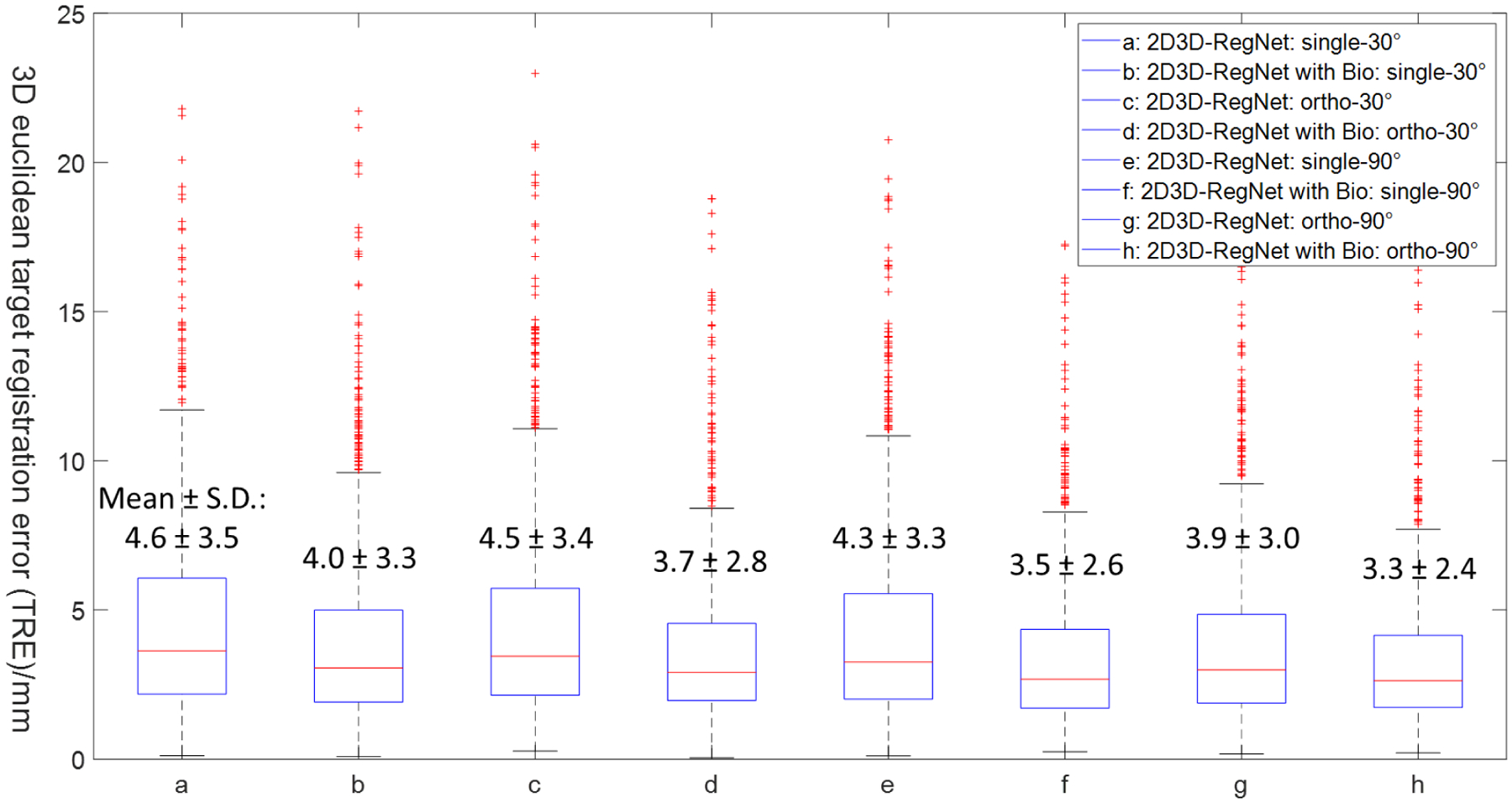
Boxplots of TRE results for different scan angle scenarios, and comparisons between 2D3D-RegNet and 2D3D-RegNet with additional biomechanical modeling fine-tuning. The 25 percentile (Q1), median and 75 percentile (Q3) of the data were respectively marked by the upper, middle and lower horizontal lines of each boxplot. The ‘+’ markers represent outliers outside the whiskers, and the upper whisker extends to the data point of value smaller than or equal to Q3 + 1.5 × (Q3 − Q1), and the lower whisker extends to the data point of value larger than or equal to Q1 − 1.5 × (Q3 − Q1). Four scan angle scenarios were included in this evaluation: single-view 30°, ortho-view 30°, single-view 90° and ortho-view 90° (Fig. 3). Bio: biomechanical modeling.
In this study, the network was built via a one-pass design to generate the DVFs (Fig. 1). Using a pyramid structure of multi-scale resolution levels might help to further improve the deformation results, especially for areas with large deformations (Hu et al., 2019; Jiang et al., 2020; Fu et al., 2020). However, the memory limit of the GPU card currently prohibits us from deploying an end-to-end, pyramid-style 2D3D-RegNet for training and evaluation. Previous studies have also found replacing the isotropic deformation regularization term with an anisotropic energy function can preserve the sliding motion around organ boundaries and improve the deformation accuracy (Dang et al., 2016). Both strategies can potentially further increase the accuracy of 2D3D-RegNet and should be evaluated in future.
V. Conclusion:
We developed an unsupervised 2D-3D deformable registration network, 2D3D-RegNet, for efficient and accurate CBCT estimation from limited-angle or sparse-view on-board projections. 2D3D-RegNet solves DVFs to map prior high-quality CT/CBCT images to new CBCTs, which fits well into the adaptive radiotherapy workflow to allow automatic contour propagation and dose accumulation. 2D3D-RegNet solves DVFs with similar accuracy as the traditional iterative 2D-3D deformable registration network, while only takes a few seconds as compared to several hours of the latter method. The 2D3D-RegNet showed robustness to scan angle offsets and sampling frequency variations, while additional comprehensive evaluations are needed. Future studies on 2D3D-RegNet are warranted to further improve its accuracy, especially for orthogonally-arranged scan angle scenarios.
Acknowledgment
The author acknowledges funding support from the US National Institutes of Health (R01 CA240808), and from a UT Southwestern Radiation Oncology Departmental Seed Grant.
The author would like to thank Kai Wang at the UT Southwestern Medical Center for help trouble-shooting the deep learning platform used in this study. The author would also like to thank Dr. Rene Werner at the University Medical Center Hamburg-Eppendorf, Dr. Wei Lu at the Memorial Sloan Kettering Cancer Center, and Dr. Daniel Low at the University of California, Los Angeles for sharing the data used in this study.
Footnotes
Conflict of Interest Statement
There is no conflict of interest to disclose with regard to the reported study.
References:
- Abadi M, Barham P, Chen J, Chen Z, Davis A, Dean J, Devin M, Ghemawat S, Irving G and Isard M 12th {USENIX} symposium on operating systems design and implementation ({OSDI} 16),2016), vol. Series) pp 265–83 [Google Scholar]
- Balakrishnan G, Zhao A, Sabuncu MR, Guttag J and Dalca AV 2019. Voxelmorph: a learning framework for deformable medical image registration IEEE transactions on medical imaging 38 1788–800 [DOI] [PubMed] [Google Scholar]
- Ballhausen H, Li M, Ganswindt U and Belka C 2018. Shorter treatment times reduce the impact of intra-fractional motion : A real-time 4DUS study comparing VMAT vs. step-and-shoot IMRT for prostate cancer Strahlenther Onkol 194 664–74 [DOI] [PubMed] [Google Scholar]
- Biguri A, Dosanjh M, Hancock S and Soleimani M 2017. A general method for motion compensation in x-ray computed tomography Phys Med Biol 62 6532–49 [DOI] [PubMed] [Google Scholar]
- Brock RS, Docef A and Murphy MJ 2010. Reconstruction of a cone‐beam CT image via forward iterative projection matching Medical physics 37 6212–20 [DOI] [PMC free article] [PubMed] [Google Scholar]
- Chen M, Lu W, Chen Q, Ruchala KJ and Olivera GH 2008. A simple fixed-point approach to invert a deformation field Med Phys 35 81–8 [DOI] [PubMed] [Google Scholar]
- Chen X, Ouyang L, Yan H, Jia X, Li B, Lyu Q, Zhang Y and Wang J 2017. Optimization of the geometry and speed of a moving blocker system for cone-beam computed tomography scatter correction Med Phys 44 e215–e29 [DOI] [PMC free article] [PubMed] [Google Scholar]
- Dang J, Yin FF, You T, Dai C, Chen D and Wang J 2016. Simultaneous 4D‐CBCT reconstruction with sliding motion constraint Medical Physics 43 5453–63 [DOI] [PMC free article] [PubMed] [Google Scholar]
- Davison ME 1983. The Ill-Conditioned Nature of the Limited Angle Tomography Problem Siam J Appl Math 43 428–48 [Google Scholar]
- Eppenhof KA and Pluim JP 2018. Pulmonary CT registration through supervised learning with convolutional neural networks IEEE transactions on medical imaging 38 1097–105 [DOI] [PubMed] [Google Scholar]
- Feldkamp LA, Davis LC and Kress JW 1984. Practical Cone-Beam Algorithm J Opt Soc Am A 1 612–9 [Google Scholar]
- Frikel J and Quinto ET 2013. Characterization and reduction of artifacts in limited angle tomography Inverse Probl 29 [Google Scholar]
- Fu Y, Lei Y, Wang T, Higgins K, Bradley JD, Curran WJ, Liu T and Yang X 2020. LungRegNet: an unsupervised deformable image registration method for 4D‐CT lung Medical Physics 47 1763–74 [DOI] [PMC free article] [PubMed] [Google Scholar]
- Gobbi DG and Peters TM 2003. Generalized 3D nonlinear transformations for medical imaging: an object-oriented implementation in VTK Comput Med Imaging Graph 27 255–65 [DOI] [PubMed] [Google Scholar]
- Gulli A and Pal S 2017. Deep learning with Keras: Packt Publishing Ltd; ) [Google Scholar]
- Hansen DC, Landry G, Kamp F, Li M, Belka C, Parodi K and Kurz C 2018. ScatterNet: A convolutional neural network for cone‐beam CT intensity correction Medical Physics 45 4916–26 [DOI] [PubMed] [Google Scholar]
- Hu X, Kang M, Huang W, Scott MR, Wiest R and Reyes M International Conference on Medical Image Computing and Computer-Assisted Intervention,2019), vol. Series): Springer; ) pp 382–90 [Google Scholar]
- Hugo G, Weiss E, Sleeman W, Balik S, Keall P, Lu J and Williamson J 2016. Data from 4D lung imaging of NSCLC patients Cancer Imaging Arch [Google Scholar]
- Jaffray DA and Siewerdsen JH 2000. Cone-beam computed tomography with a flat-panel imager: initial performance characterization Med Phys 27 1311–23 [DOI] [PubMed] [Google Scholar]
- Jiang Z, Yin FF, Ge Y and Ren L 2020. A multi-scale framework with unsupervised joint training of convolutional neural networks for pulmonary deformable image registration Phys Med Biol 65 015011. [DOI] [PMC free article] [PubMed] [Google Scholar]
- Keall PJ, Mageras GS, Balter JM, Emery RS, Forster KM, Jiang SB, Kapatoes JM, Low DA, Murphy MJ, Murray BR, Ramsey CR, Van Herk MB, Vedam SS, Wong JW and Yorke E 2006. The management of respiratory motion in radiation oncology report of AAPM Task Group 76 Med Phys 33 3874–900 [DOI] [PubMed] [Google Scholar]
- Kerner GS, Fischer A, Koole MJ, Pruim J and Groen HJ 2015. Evaluation of elastix-based propagated align algorithm for VOI-and voxel-based analysis of longitudinal 18 F-FDG PET/CT data from patients with non-small cell lung cancer (NSCLC) EJNMMI research 5 15. [DOI] [PMC free article] [PubMed] [Google Scholar]
- Klein S, Staring M, Murphy K, Viergever MA and Pluim JP 2009. Elastix: a toolbox for intensity-based medical image registration IEEE transactions on medical imaging 29 196–205 [DOI] [PubMed] [Google Scholar]
- Liu F, Ahunbay E, Lawton C and Li XA 2014. Assessment and management of interfractional variations in daily diagnostic-quality-CT guided prostate-bed irradiation after prostatectomy Med Phys 41 031710. [DOI] [PubMed] [Google Scholar]
- Lu W, Chen M-L, Olivera GH, Ruchala KJ and Mackie TR 2004. Fast free-form deformable registration via calculus of variations Physics in Medicine & Biology 49 3067. [DOI] [PubMed] [Google Scholar]
- Marchant TE, Joshi KD and Moore CJ 2018. Accuracy of radiotherapy dose calculations based on cone-beam CT: comparison of deformable registration and image correction based methods Physics in Medicine & Biology 63 065003. [DOI] [PubMed] [Google Scholar]
- Ouadah S, Jacobson M, Stayman JW, Ehtiati T, Weiss C and Siewerdsen JH 2017. Correction of patient motion in cone-beam CT using 3D-2D registration Physics in medicine and biology 62 8813–31 [DOI] [PMC free article] [PubMed] [Google Scholar]
- Purdie TG, Bissonnette JP, Franks K, Bezjak A, Payne D, Sie F, Sharpe MB and Jaffray DA 2007. Cone-beam computed tomography for on-line image guidance of lung stereotactic radiotherapy: localization, verification, and intrafraction tumor position Int J Radiat Oncol Biol Phys 68 243–52 [DOI] [PubMed] [Google Scholar]
- Ren L, Chen Y, Zhang Y, Giles W, Jin J and Yin FF 2016. Scatter Reduction and Correction for Dual-Source Cone-Beam CT Using Prepatient Grids Technol Cancer Res Treat 15 416–27 [DOI] [PMC free article] [PubMed] [Google Scholar]
- Ren L, Chetty IJ, Zhang J, Jin JY, Wu QJ, Yan H, Brizel DM, Lee WR, Movsas B and Yin FF 2012. Development and clinical evaluation of a three-dimensional cone-beam computed tomography estimation method using a deformation field map Int J Radiat Oncol Biol Phys 82 1584–93 [DOI] [PubMed] [Google Scholar]
- Ren L, Zhang Y and Yin FF 2014. A limited-angle intrafraction verification (LIVE) system for radiation therapy Med Phys 41 020701. [DOI] [PubMed] [Google Scholar]
- Rivenson Y, Zhang Y, Günaydın H, Teng D and Ozcan A 2018. Phase recovery and holographic image reconstruction using deep learning in neural networks Light: Science & Applications 7 17141- [DOI] [PMC free article] [PubMed] [Google Scholar]
- Ronneberger O, Fischer P and Brox T International Conference on Medical image computing and computer-assisted intervention,2015), vol. Series): Springer; ) pp 234–41 [Google Scholar]
- Shun M, Wang ZJ and Rui L 2016. A CNN Regression Approach for Real-Time 2D/3D Registration IEEE transactions on medical imaging 35 1352–63 [DOI] [PubMed] [Google Scholar]
- Siddon RL 1985a. Fast calculation of the exact radiological path for a three‐dimensional CT array Medical physics 12 252–5 [DOI] [PubMed] [Google Scholar]
- Siddon RL. Prism representation: a 3D ray-tracing algorithm for radiotherapy applications. Physics in Medicine & Biology. 1985b;30:817. doi: 10.1088/0031-9155/30/8/005. [DOI] [PubMed] [Google Scholar]
- Staring M, Klein S, Reiber JH, Niessen WJ and Stoel BC 2010. Pulmonary image registration with elastix using a standard intensity-based algorithm Medical Image Analysis for the Clinic: A Grand Challenge 73–9 [Google Scholar]
- Syben C, Michen M, Stimpel B, Seitz S, Ploner S and Maier AK 2019a. PYRO‐NN: Python reconstruction operators in neural networks Medical physics 46 5110–5 [DOI] [PMC free article] [PubMed] [Google Scholar]
- Syben C, Michen M, Stimpel B, Seitz S, Ploner S and Maier AK 2019b. Technical Note: PYRO-NN: Python reconstruction operators in neural networks Med Phys 46 5110–5 [DOI] [PMC free article] [PubMed] [Google Scholar]
- Thing RS, Bernchou U, Mainegra-Hing E and Brink C 2013. Patient-specific scatter correction in clinical cone beam computed tomography imaging made possible by the combination of Monte Carlo simulations and a ray tracing algorithm Acta Oncologica 52 1477–83 [DOI] [PubMed] [Google Scholar]
- Vandemeulebroucke J, Rit S, Kybic J, Clarysse P and Sarrut D 2011. Spatiotemporal motion estimation for respiratory‐correlated imaging of the lungs Medical physics 38 166–78 [DOI] [PubMed] [Google Scholar]
- Viola P and Wells WM III 1997. Alignment by maximization of mutual information International journal of computer vision 24 137–54 [Google Scholar]
- Wang G, Li W, Zuluaga MA, Pratt R, Patel PA, Aertsen M, Doel T, David AL, Deprest J and Ourselin S 2018. Interactive medical image segmentation using deep learning with image-specific fine tuning IEEE transactions on medical imaging 37 1562–73 [DOI] [PMC free article] [PubMed] [Google Scholar]
- Wang J and Gu X 2012. High-quality four-dimensional cone-beam CT by deforming prior images Physics in Medicine & Biology 58 231. [DOI] [PubMed] [Google Scholar]
- Wang J and Gu X 2013. Simultaneous motion estimation and image reconstruction (SMEIR) for 4D cone-beam CT Med Phys 40 101912. [DOI] [PubMed] [Google Scholar]
- Wang Z and Bovik AC 2009. Mean squared error: Love it or leave it? A new look at signal fidelity measures IEEE signal processing magazine 26 98–117 [Google Scholar]
- Werner R, Ehrhardt J, Schmidt R and Handels H 2009. Patient-specific finite element modeling of respiratory lung motion using 4D CT image data Med Phys 36 1500–11 [DOI] [PubMed] [Google Scholar]
- Willmott CJ and Matsuura K 2005. Advantages of the mean absolute error (MAE) over the root mean square error (RMSE) in assessing average model performance Climate research 30 79–82 [Google Scholar]
- Wurfl T, Hoffmann M, Christlein V, Breininger K, Huang Y, Unberath M and Maier AK 2018. Deep Learning Computed Tomography: Learning Projection-Domain Weights From Image Domain in Limited Angle Problems IEEE Trans Med Imaging 37 1454–63 [DOI] [PubMed] [Google Scholar]
- Yan D, Vicini F, Wong J and Martinez A 1997. Adaptive radiation therapy Physics in Medicine & Biology 42 123. [DOI] [PubMed] [Google Scholar]
- Zhang H, Li L, Qiao K, Wang L, Yan B, Li L and Hu G 2016a. Image prediction for limited-angle tomography via deep learning with convolutional neural network arXiv preprint arXiv:1607.08707 [Google Scholar]
- Zhang Y, Chen L, Li B, Folkert M, Jia X, Gu X and Wang J MEDICAL PHYSICS,2018), vol. Series 45): WILEY 111 RIVER ST, HOBOKEN 07030–5774, NJ USA: ) pp E162–E [Google Scholar]
- Zhang Y, Folkert MR, Li B, Huang X, Meyer JJ, Chiu T, Lee P, Tehrani JN, Cai J and Parsons D 2019. 4D liver tumor localization using cone-beam projections and a biomechanical model Radiotherapy and Oncology 133 183–92 [DOI] [PMC free article] [PubMed] [Google Scholar]
- Zhang Y, Ren L, Ling CC and Yin FF 2013a. Respiration-phase-matched digital tomosynthesis imaging for moving target verification: a feasibility study Med Phys 40 071723. [DOI] [PubMed] [Google Scholar]
- Zhang Y, Ren L, Vergalasova I and Yin F-F 2017. Clinical study of orthogonal-view phase-matched digital tomosynthesis for lung tumor localization Technology in cancer research & treatment 16 866–78 [DOI] [PMC free article] [PubMed] [Google Scholar]
- Zhang Y, Tehrani JN and Wang J 2016b. A biomechanical modeling guided CBCT estimation technique IEEE transactions on medical imaging 36 641–52 [DOI] [PMC free article] [PubMed] [Google Scholar]
- Zhang Y, Yin F-F, Pan T, Vergalasova I and Ren L 2015a. Preliminary clinical evaluation of a 4D-CBCT estimation technique using prior information and limited-angle projections Radiotherapy and Oncology 115 22–9 [DOI] [PMC free article] [PubMed] [Google Scholar]
- Zhang Y, Yin FF and Ren L 2015b. Dosimetric verification of lung cancer treatment using the CBCTs estimated from limited-angle on-board projections Med Phys 42 4783–95 [DOI] [PMC free article] [PubMed] [Google Scholar]
- Zhang Y, Yin FF, Segars WP and Ren L 2013b. A technique for estimating 4D‐CBCT using prior knowledge and limited‐angle projections Medical physics 40 121701. [DOI] [PubMed] [Google Scholar]
- Zhao F, Huang Q and Gao W 2006. IEEE International Conference on Acoustics Speech and Signal Processing Proceedings,2006), vol. Series 2): IEEE; ) pp II–II [Google Scholar]