Abstract
The straightforward synthesis of directly fused porphyrins (porphyrin tapes) from 5,15-diphenyl porphyrinato nickel(ii) complexes with different substituents on the phenyl rings is achieved while processing from the gas phase. The porphyrin tapes, exhibiting NIR absorption, are readily obtained in thin film form. The gas phase approach cuts the need for solubilizing groups allowing for the first time the study of their conductivity according to the substituent. 2-Point probe and conductivity AFM measurements evidence that reducing the size of the meso substituents, phenyl < mesityl < di(3,5-tert-butyl)phenyl < di(2,6-dodecyloxy)phenyl, improves the thin film conductivity by several orders of magnitude. Density functional theory and gel permeation chromatography, correlate this improvement to changes in the intermolecular distances and molecular geometry. Furthermore, the oCVD of porphyrins with free ortho-phenyl positions causes intramolecular dehydrogenative side reactions inducing a complete planarization of the molecule. This molecular flattening drastically affects the π–π stacking between the porphyrins further enhancing the electronic properties of the films.
This work reports the strong correlation between the conductivity of fused porphyrins thin films and the porphyrin substituents.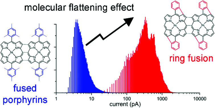
Introduction
Porphyrins are versatile compounds that are used in a broad range of applications such as catalysis,1–7 photovoltaics8–10 or photodynamic therapy.11–14 They have fascinating optical and electronic properties, which can be tuned by structural modifications affecting electronic and steric properties.15–18 Particularly, the extension of the porphyrin π-system plays an important role in the enhancement of their optical properties yielding NIR absorbers.19–23 One application of these materials is the production of bulk heterojunction solar cells.24
The extension of the porphyrin π-conjugation generally increases the absorption in the Q-band region and widens the fraction of the solar spectrum that can be used for the conversion of energy.24 The direct fusion of porphyrinic cores with free β and meso positions into conjugated polymers further pushes the optoelectronic boundaries of the porphyrins yielding chromophores with very low HOMO–LUMO gaps (oligomers) or bandgaps (polymers) reaching the infrared region.16 These highly conjugated porphyrin-based systems exhibit interesting chemical and physical properties such as two-photon absorption,25 increased electro-catalytic activities,5 low conductance attenuation factors26,27 and switchable carrier species in liquid crystalline semiconductors.28
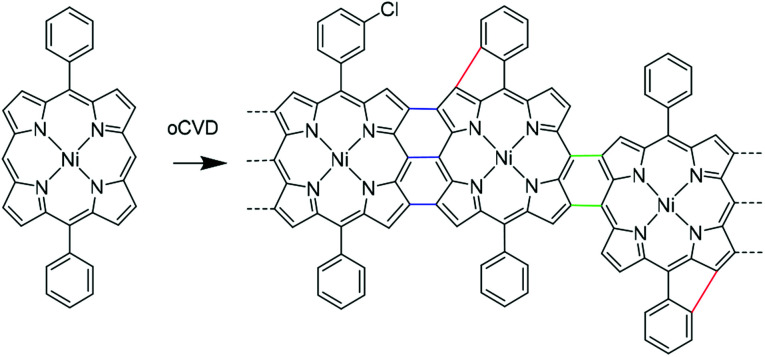
The unique properties of fused porphyrins fostered the development of a wide series of synthetic strategies aiming to obtain directly fused porphyrins (porphyrin tapes) (Scheme 1). The main synthetic route towards directly fused porphyrins involves the solution-based dehydrogenative coupling of metalloporphyrins with transition metal salts such as AgX,29 CuX2,30,31 FeX3,32 WCl6 33 or organic oxidants such as [(p-Br–C6H4)3N][SbCl6],34 or a mixture of 2,3-dichloro-5,6-dicyano-1,4-benzoquinone and Sc(OTf)3.16 Solution-based methods have enabled the preparation of fused porphyrin tapes from several metalloporphyrin complexes such as zinc(ii), nickel(ii), palladium(ii) and copper(ii).16,30,35,36 However, porphyrinoids, and more particularly π-extended porphyrins, usually experience very low solubility and solubilizing substituents are required to allow both their synthesis and integration into optoelectronic devices.
Scheme 1. oCVD reaction for NiDPP. The products are characterized by the incorporation of chlorine (the position of the Cl atom in the structure is merely representative). We also observed double (green) and triple (blue) links between the monomer units and the dehydrogenative cyclization of the phenyl substituent and the porphyrin macrocycle (red).
Although the introduction of substituents such as long alkyl chains increases the solubility and hence processability of such planar chromophores, their effect on π–π stacking adversely affects the device performance.24,37 Fused porphyrin tapes require side chains to retain the solubility necessary to achieve high degree of polymerization.29 The difficult processability, strongly dependent on the substituents, of porphyrin tapes in thin film form has hindered the study of the electrical properties of the bulk materials and their application in advanced devices. We recently developed a gas phase approach for the simultaneous synthesis and deposition of fused porphyrin thin films.38 This approach relies on the oxidative chemical vapour deposition (oCVD)39,40 reaction of porphyrins with free meso and β positions using a suitable volatile oxidant (preferentially FeCl3) for dehydrogenative coupling. The oCVD technique is been mainly used for the synthesis of poly(3,4-ethylenedioxythiophene) (PEDOT)41–43 and polyaniline (PANI)44 finding application in organic electronics,45 volatile compound detectors46–48 and supercapacitors.49,50
Furthermore, the oxidant acts as doping agent directly yielding conductive thin films on virtually any substrates including sensitive substrates such as paper and polymers.38 In addition of allowing the deposition of patterned, smooth and thickness-controlled fused porphyrin thin films, this oCVD approach does not require solubilizing substituents. Consequently, substituents can be used to implement advanced functionalities in the material beyond mere solubility.
In contrast to solution-based approaches, further dehydrogenative couplings (loss of 2H) were detected in both the porphyrin units and fused porphyrin oligomers as evidenced by laser desorption ionisation high-resolution mass spectrometry (LDI-HRMS).33 Cyclization of phenyl rings on the porphyrin macrocycle accounts for these coupling reactions (Scheme 1). The Cl2(g) produced during the reaction leading to a second oxidation of the porphyrin could account for this reaction.33,51,52 The fusion of aromatic rings on the porphyrin core was already observed in presence of iron oxidants, yet electron-donating groups on the phenyl rings are usually required.20,21,53 However, so far the poor solubility of the oligomeric and polymeric products of the oCVD process hindered an unequivocal assignment and a proper characterization of the cyclization reaction.
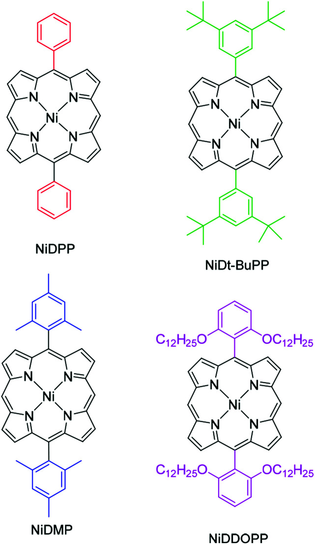
In this study, we investigate the intramolecular cyclization reaction in the fused porphyrin thin films obtained via oCVD, their impact on the π–π stacking interactions and the resulting effect on conductivity. To this end, 5,15-diphenyl porphyrinato nickel(ii) complexes with different substituents on the phenyl rings were employed in the oCVD process, namely 5,15-(diphenyl)porphyrinato nickel(ii) (NiDPP), 5,15-(di-3,5-di-tert-butylphenyl)porphyrinato nickel(ii) (NiDt-BuPP), 5,15-(dimesityl)porphyrinato nickel(ii) (NiDMP) and 5,15-(di-2,6-dodecyloxyphenyl)porphyrinato nickel(ii) (NiDDOPP) (Scheme 2). Nickel(ii) complexes were chosen due to the already proven high stability of the Ni2+ in the porphyrin core during the oCVD process.33,38,54NiDPP and NiDt-BuPP possess free ortho positions on the phenyl rings, potentially allowing an intramolecular cyclization reaction. In NiDMP and NiDDOPP these positions are blocked preventing intramolecular dehydrogenative coupling reactions. Furthermore, the size of the porphyrin substituent R increases in the order phenyl < mesityl < di(tert-butyl)phenyl < di(alkoxy)phenyl in NiDPP, NiDMP, NiDt-BuPP and NiDDOPP, respectively. This steric aspect likely affects the intermolecular π–π stacking interaction in oCVD films. Finally, the substituents should modify the electronic properties, especially the redox potential for the Ni(P)/[Ni(P)]˙+ oxidation of the monomer, which initiates the intra- and intermolecular dehydrogenative coupling reactions of the nickel porphyrins.33,34
Scheme 2. Structure of the porphyrins employed in the experiments.
Hence, steric and electronic effects on the resulting film properties (absorptivity, homogeneity, morphology and conductivity) imposed by the substituents are addressed employing High Resolution Mass Spectrometry (HRMS), Gel Permeation Chromatography (GPC), UV/Vis/NIR spectroscopy, 2-point probe I/V measurements, Conductive Atomic Force Microscopy (C-AFM) and Helium Ion Microscopy (HIM). Furthermore, Density Functional Theory (DFT) calculations on pairs of nickel porphyrins with different meso substituents deliver information on the conceivable porphyrin–porphyrin interactions in the film. Finally, we correlate the obtained structural information on the oCVD films to their conductivity.
Results and discussion
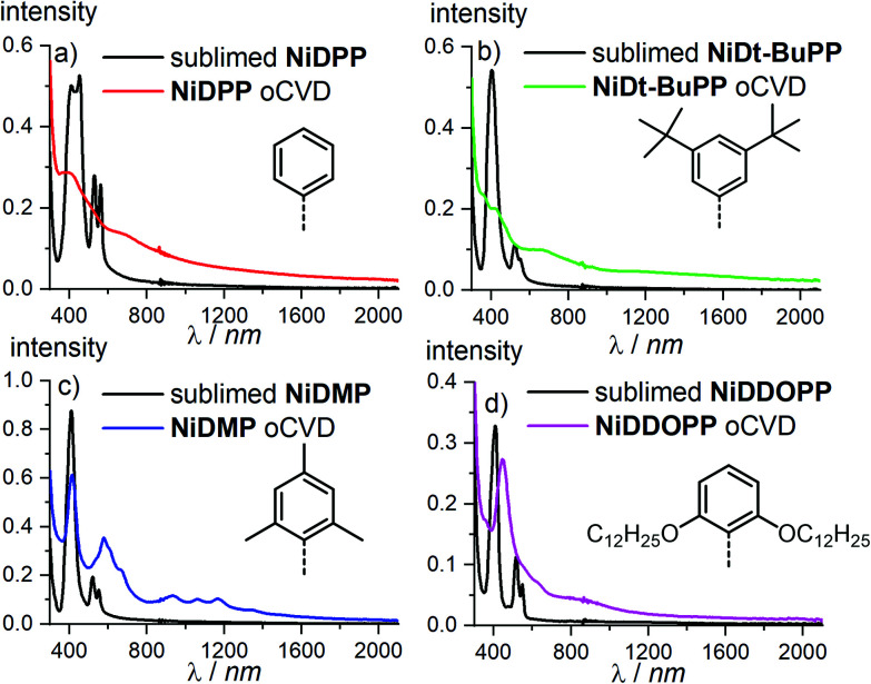
Prior to sublimation under oxidative conditions, the thermal stability of each porphyrin was controlled by thermogravimetry (Fig. S1†). All the porphyrins are thermally stable up to at least 300 °C confirming their suitability for oCVD processing. The first oxidation potentials of NiDPP, NiDMP, NiDDt-BuPP and NiDDOPP were determined by cyclic voltammetry in CH2Cl2/[nBu4N][PF6] solution as Ep = 0.57, 0.60, 0.55 and 0.50 V versus ferrocene, respectively (Fig. S2†). This demonstrates the influence of the meso substituents on the potential of the Ni(P)/[Ni(P)]˙+ redox couple. Particularly, a strong effect is observed for the NiDDOPP showing the lower value in the series thanks to the mesomeric effect of the two alkoxy substituents on the phenyl rings. In a custom built reactor (Fig. S3†),38 we performed the oCVD reaction of the differently substituted nickel porphyrins using FeCl3 as oxidant and silicon wafers or microscope slides as substrates for the deposition of the films. For the sake of comparison, the porphyrin/oxidant molar ratio was kept constant for each deposition varying the sublimation temperature of the porphyrin (Table S1 ESI†). The thickness of the oCVD coatings was 169, 520, 355 and 560 nm for NiDPP, NiDMP, NiDDt-BuPP and NiDDOPP, respectively, according to profilometry (Table S2†). All oCVD coatings exhibit a clearly visible colour change when compared to the reference coatings obtained from mere sublimation of the respective monomer (Fig. S4†). The sublimed reference coatings are pink (NiDDOPP), orange (NiDMP and NiDPP) and yellow (NiDt-BuPP), while all oCVD coatings exhibit a green, intense coloration. This is consistent with previous studies on oCVD polymerization of porphyrins33,38,54 hinting to retention of the porphyrin macrocycle upon sublimation and oxidative dehydrogenation and polymerization. The colour changes are also reflected in the UV/Vis/NIR spectra (Fig. 1). All oCVD films absorb up to the NIR region as expected by fused porphyrin tapes. NiDPP and NiDt-BuPP exhibit a significant broadening of the absorption in the Soret band region (Fig. 1a and b). As we already observed, this is consistent with the formation of fused porphyrins with intramolecular dehydrogenative cyclizations (Scheme 1) causing a redshift of the Soret band and, consequently, a general broadening of the spectrum.38,54–56 Differently, the oCVD film of the mesityl derivative NiDMP shows several well defined absorption bands between 800 nm and 1500 nm in addition to a weakly broadened Soret band. This points to the formation of oligomers/polymers lacking intramolecular dehydrogenative cyclizations which is rationalized by the blocked ortho positions of the mesityl substituents. Similarly, NiDDOPP lacks free ortho positions on the phenyl ring preventing the cyclization. Consequently, the NiDDOPP oCVD film exhibits well-defined Soret bands. Unexpectedly, the Soret band of the NiDDOPP oCVD coating is red-shifted from 407 to 448 nm. This bathochromic shift might be related to ring chlorination of the porphyrin57 or to a further coupling of the aryl rings (see below).
Fig. 1. UV/VIS/NIR spectra of (a) NiDPP, (b) NiDt-BuPP, (c) NiDMP and (d) NiDDOPP oCVD coatings and their respective references.
The NiDPP oCVD coating is insoluble contrarily to NiDMP and NiDt-BuPP oCVD coatings thanks to their solubilizing substituents (Fig. S5†). Surprisingly, even with the long alkoxy substituents, the NiDDOPP oCVD coating, is completely insoluble in THF or toluene even at boiling temperatures. This indicates a particularly high degree of polymerization or a high degree of chlorination of the polymer (cf. red-shift of Soret bands) that is known to significantly reduce the solubility of the porphyrins.58 Furthermore, alkoxy substituted aryl groups are quite electron rich and easy to oxidize (see above). Consequently, biaryl formation between OC12H25-substituted aryl groups (Scheme S2†) is conceivable and has been observed with simpler OCH3 substituted arenes, e.g. using molybdenum(v) oxidants or iron(iii) chloride.59–63 This additional intermolecular C–C coupling via the aryl substituents might lead to cross-linking of the porphyrin oligomers and polymers thus reducing their solubility. The resulting different (biaryl) substituents furthermore could account for the shifted Soret bands of the NiDDOPP oCVD film.
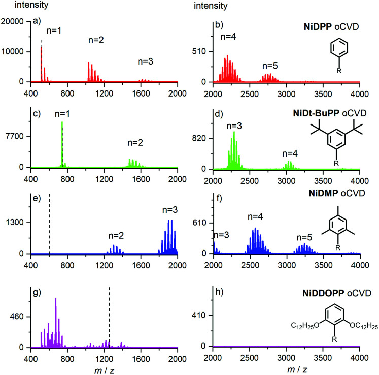
High resolution mass spectrometry (HRMS) was used to assess both the effective oligomerization and the intramolecular ring fusion Mn–x2H reactions occurring during oCVD deposition. The analysis confirmed the presence of oligomers for all oCVD coatings, except for the film derived from OC12H25-substituted NiDDOPP. Its mass spectrum seems to only reveal low molecular weight fragments with low intensity (Fig. 2). This is consistent with the above suggested additional cross-linking via the alkoxy-substituted aryl substituents. Indeed samples with a high level of entanglement are well known to be rather difficult to ionize in their intact form. As a result, the energy provided by the laser most likely induces fragmentation of the chains, explaining the presence of small ions (<800 m/z), with no consistent molecular formula identification. To ensure that the absence of signal is not related to the limitation of the HRMS analyser (m/z < 4000), the range of detection was extended to high masses by performing both solvent-free MALDI-TOF and LDI-TOF without any success. This strongly supports the idea of a highly entangled/crosslinked insoluble system. In addition to polymerization, chlorination of the poly(porphyrins) is observed for NiDPP, NiDt-BuPP and NiDMP as evidenced by the family of peak distributions related to the repeating increment of a chlorine atom mass for each oligomer (Fig. 2). This reaction was known for chlorine-containing oxidants (i.e. FeCl3, CuCl2 and Cu(ClO4)2·6H2O)54 in the oCVD of porphyrins.
Fig. 2. LDI-HRMS of the (a and b) NiDPP (c and d) NiDtBuPP (e and f) NiDMP (g and h) NiDDOPP oCVD coatings. The expected mass of the monomer is evidenced from the dashed line. Ions are detected as radical cations [M]˙+. Two scan events were used to acquire spectra within a broad mass range (400–2000 and 2000–4000 m/z).
Due to the lack of monomer and oligomer signals of the NiDDOPP film, the extent of chlorine incorporation is unavailable from mass spectrometry in this case. Yet, as chlorination has been observed in all cases so far using FeCl3 as oxidant,33,38,54 we suspect that this is likely also the case for NiDDOPP films. To confirm this idea, we performed a new oCVD deposition of NiDDOPP decreasing the substrate temperature to 50 °C to reduce the reactivity and avoid a deep reticulation of the system, favouring its ease of ionization via LDI-HRMS.
As expected, the new MS spectrum allowed the discrimination of several species. Particularly, this experiment confirmed the formation of highly chlorinated monomers and dimers singly, doubly and triply linked (Fig. S6 & S7†). Interestingly, signals related to the cleavage of one or two ether groups with subsequent formation of phenols are observed (Fig. S6 and Scheme S2†). It is not clear if this reaction is related to the laser irradiation or to the HCl formed during the oxidative polymerization.64 All these experiments hint undeniably to a polymerization process occurring for all nickel porphyrins irrespective of the substituent.
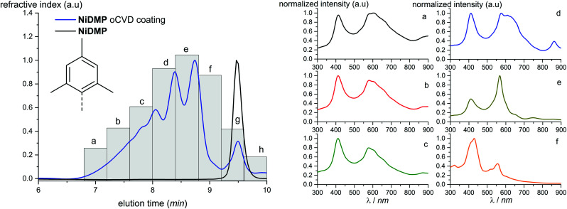
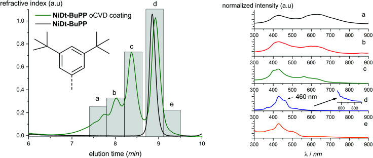
Parts of the NiDt-BuPP and NiDMP oCVD coatings are sufficiently soluble allowing solution based studies. For this reason, the two oCVD coatings were investigated by Gel Permeation Chromatography coupled to Electrospray Ionization High resolution Mass Spectrometry (GPC × ESI-HRMS). As opposed to LDI, ESI ionization allows for the formation of multiply charged ions (z > 1), thus permitting to detect higher masses. For instance, the NiDMP oCVD film mass spectrum shows soluble oligomers up to a degree of polymerization of 7 (Fig. S8†). An advantage of the online GPC × ESI-HRMS analysis is the possibility to report specific m/z as function of elution time. The results are plotted in the Extracted Ion Chromatograms (EIC) (Fig. S9 and S10†). In addition to an MS coupling, the GPC analyses of the soluble samples were also combined with differential refractive index detection, which typically provides a fairly representative picture of the sample in terms of relative abundance of the species. The intensity of the unreacted monomer signal (retention time determined from the NiDMP and NiDt-BuPP reference chromatogram) confirms the higher conversion of NiDMP compared to NiDt-BuPP (Fig. 3 and 4). This might be ascribed to the absence of the intramolecular dehydrogenative cyclization in NiDMP and a thus preferred polymerization. Interestingly, the GPC analysis of NiDt-BuPP (Fig. 4) gives rise to an intense monomer signal (8.9 minutes) shifted as compared to the chromatogram of the non-polymerized reference (8.8 minutes).
Fig. 3. Chromatogram obtained from the GPC analysis of NiDMP. UV-Vis spectra in the range 300–900 nm were recorded with regular time (indicated with the letters a–h). The corresponding spectra are reported on the right (a–f). The spectra of the monomeric region (g and h) are reported in the ESI.†.
Fig. 4. Chromatogram obtained from the GPC analysis of NiDt-BuPP oCVD coating and from NiDt-BuPP. UV-Vis spectra in the range 300–900 nm were recorded with at specific time (indicated with the letters a–e). The corresponding spectra are reported on the right.
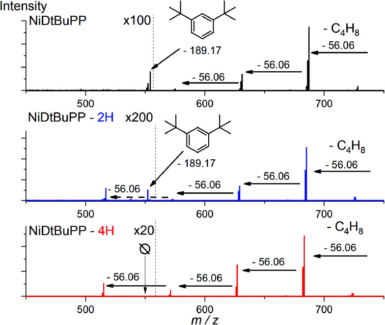
Thanks to the online MS, we assigned the chromatographic peak to the protonated fused monomers NiDt-BuPP-2H (741.35 m/z) and NiDt-BuPP-4H (739.33 m/z) with elution time of 8.9 and 9.0 minutes respectively (Fig. S11†). The shift towards smaller hydrodynamic volume can be rationalized with the direct impact of the ring fusion on the molecular shape as shown by DFT calculations (see below). To undoubtedly demonstrate that the 2H elimination is related to a cyclization between the phenyl and porphyrinic ring, a structural MS/MS analysis of the ions with m/z = 743.36, 741.35 and 739.33 assigned to NiDt-BuPP, NiDt-BuPP-2H and NiDt-BuPP-4H respectively, was included in the GPC × ESI-HRMS method (Fig. 5).
Fig. 5. Collision Induced Dissociation (CID) MS/MS analysis of NiDt-BuPP (m/z = 743.36), NiDt-BuPP-2H (m/z = 741.35) and NiDtBuPP-4H (m/z = 739.33). Normalized CID energy was set to 70. With ESI-HRMS, parent ions are detected as proton adducts [M + H]+.
Because of their new C–C bond between the phenyl substituent and the porphyrin, fused monomers are less likely to lose a phenyl ring. Indeed, while the loss of a phenyl ring is observed in the MS/MS spectra of NiDt-BuPP and NiDt-BuPP-2H, no phenyl ring is eliminated from NiDt-BuPP-4H (Fig. 5). A detailed list of the fragments is given Table S3.† Both EIC and MS/MS confirm the dehydrogenative ring fusion reaction occurring during the oCVD deposition of phenyl substituted porphyrins with free ortho positions and its effect on the porphyrin geometry. Finally, the UV/Vis spectra (Fig. 4d) exhibit a red-shifted shoulder (460 nm), and an increased number of Q-bands. This agrees with the spectra reported for phenyl fused porphyrins.51,55,65 Contrarily to NiDt-BuPP, NiDMP should not undergo internal cyclisation, making it a good candidate for the in-depth investigation of oligomerization. To obtain information on the kind of links between the units, rapid UV-Vis scans from 300 to 900 nm were acquired at regular time intervals during the GPC × ESI-HRMS analysis (Fig. 3). It is important to note that the UV-Vis detector scans the full spectra in about 24 seconds and during this time, elution continues. As a result, UV-Vis spectra are only partially representative of the eluted species and a sharp feature assignment remains complicated. Nevertheless, the resulting UV-Vis spectra may be used to draw a trend and further correlation with the MS data ensures a reliable identification. Particularly, it is known that triply linked (β–β/meso–meso/β–β) porphyrins own smaller HOMO–LUMO gaps shifting the absorption more in the NIR compared to the (β–meso/meso–β) doubly linked porphyrins. As expected, the molecules with highest degrees of polymerization elute at shorter retention times from fraction a to d (EIC in Fig. S9†) and exhibit a broadened but unshifted Soret band I at 410 nm together with a widened, red-shifted band II around 574 nm. Because of instrumental limits, it was not possible to detect with precision the position of the band III typical of fused porphyrins. On the other hand, these fractions exhibit an intense absorption around 900 nm. Fraction e mainly corresponds to the elution of dimers. The presence of triply and doubly linked species was addressed by isotopic pattern simulations and comparison to HRMS (Fig. 6). Both (NiDMP)2-6H and (NiDMP)2-4H isotopic contributions are identified in the experimental spectrum.
Fig. 6. Isotopic pattern peaks corresponding to NiDMP dimers, (a) experimental spectrum, (b) theoretical isotopic pattern of triply linked dimers (A + 2 isotopic contribution = 1201.352), (c) theoretical isotopic pattern of doubly linked dimers (m/z = 1201.372). The corresponding structures are shown on the right.
Unfortunately, because of instrumental limitations, only the (NiDMP)2-4H can be observed in the UV-Vis spectra of fraction e. Particularly, doubly linked (β–meso/meso–β) porphyrin dimers show absorption maxima around 750 nm while triply linked porphyrins exhibit broader absorptions generally over 900 nm.16,32,66 These observations confirm that the synthesis of both triply and doubly linked porphyrins is possible in oCVD. We previously suggested that the initial formation of meso–meso or β–meso singly linked diporphyrins leading to triply or doubly linked dimers, respectively, is enabled by a dynamic Jahn–Teller distortion of the initially formed nickel(ii) porphyrin radical cation generating different electrophilic sites for the first C–C bond formation.33
Surprisingly, the formation of NiDMP-2H was observed in traces (Fig. 3 fraction h and Fig. S12†). This species displays an absorption spectrum similar to the one attributed to the cyclization of NiDt-BuPP (an intense shoulder at 463 nm and the presence of multiple Q-bands). The small amount obtained suggests a different reactivity of the molecule and/or a different reaction mechanism. It was shown that dimesityl groups on porphyrins can undergo dehydrogenative coupling on Cu(110) surfaces.67 We suggest that a similar reaction could be stimulated by the iron species deposited on the surface forming a six membered ring on the NiDMP molecule between the methyl group and the pyrrole ring. This new arrangement should modify the hydrodynamic volume and the symmetry of the molecule explaining the increase in the number of Q-bands and the higher retention time observed. However, the intensity of the signal of the refractive index detector evidences that this reaction is only marginal for NiDMP.
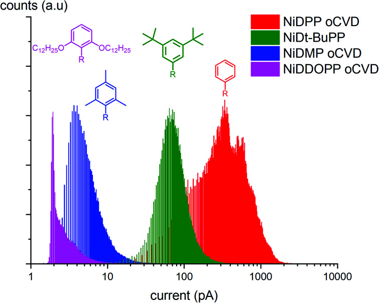
The GPC experiments showed that the substituents and the cyclization affect the reactivity and the geometry of the molecule. To investigate the effects of these structural modifications on the electrical and morphological properties of the obtained coatings, we analyzed the samples by C-AFM (yielding information on the local conductivity of the samples) and Helium Ion Microscopy (HIM) (where contrast in the image is created mainly by composition and topography). HIM images show that the NiDPP oCVD coating exhibits a rather smooth surface. Contrarily, NiDMP, NiDDOPP and NiDt-BuPP oCVD coatings exhibit a rugged surface (Fig. S13†). This strongly contrasts the smooth surface obtained from the respective sublimed monomers (Fig. S14†). Consequently, it can be assumed that the polymerization induces a different homogeneity of the surface, which relates to the polymer structure. Interestingly, the sublimed NiDDOPP monomer film shows the formation of small islands and holes (Fig. S14d†), which might be an effect of the long side chains assisting supramolecular aggregation of the monomers. It is known that the side groups affect the supramolecular aggregation of porphyrins both on surface and in solutions.68,69 Fig. S15† shows representative C-AFM images relative to the topography while Fig. S16† and 7 show the respective local conductivity acquired simultaneously and the respective representative histograms. We imaged areas of 2 × 2 μm2 avoiding the oxidant inclusions that could affect the measured conductivity. The measured roughness (Ra) (Table S4†) of the samples was calculated considering the average of at least 4 different locations on the samples. Ra varied from 1 to 20 nm. NiDDOPP with its bulky OC12H25 groups presents the highest roughness (21 ± 3 nm) average of (4.0 ± 1.0 pA) and the lowest conductivity. Coherently, NiDt-BuPP and NiDPP, undergoing the cyclization reaction, possess the highest conductivity (averages of 77 ± 15 pA and 440 ± 120 pA, respectively) and lowest roughness (Ra of 1.2 ± 0.2 nm and 4.6 ± 0.7) in the series (Table S4†). Finally, NiDMP exhibit lower conductivity (6.5 ± 0.6 pA) than NiDt-BuPP and higher roughness (10 ± 2 nm).
Fig. 7. Histograms obtained from the C-AFM measurements. The graph shows the distribution of current measured while imaging different points of the image in the oCVD samples.
2-Point probe conductivity measurements confirm this trend showing an increase in conductivity by several orders of magnitude by decreasing the size of the substituents (from 0.7 S cm−1 for NiDPP to 10−7 S cm−1 for NiDDOPP) (Fig. S17 & S18†). Obviously, larger substituents reduce the conductivity. This relation might be based on a simple steric effect preventing the π–π stacking, which is required for efficient electron transfer across porphyrin chains. Besides, this effect may also be ascribed to a dilution of the conjugated porphyrin moiety in the film. A similar relation was observed between field effect mobility and intermolecular distance in porphyrin crystals.70 Consequently, the smallest phenyl substituent in NiDPP gives rise to the highest conductivity in the series. Furthermore, the intramolecular cyclization reaction occurring in NiDPP might further enhance the planarization of the individual moieties and hence the π–π stacking. On the other hand, the very poor conductivity of NiDDOPP might be ascribed to the suggested extra cross linking via the substituents, which further prevents efficient π–π stacking by forming reticular networks. The electrical conductivity of oCVD films is drastically increased compared to solution-based films. Particularly, meso–meso singly and β–β/meso–meso/β–β triply linked porphyrins of 48 and 8 repetitive units respectively with long alkyl chains exhibit resistances between 125–670 MΩ and 50 MΩ, respectively.71 While the NiDDOPP oCVD coating exhibits a resistance of 400 MΩ, NiDPP, NiDt-BuPP and NiDMP show much smaller resistances of 100 Ω, 230 KΩ and 400 KΩ, respectively (Fig. S17†). Obviously, the oCVD of porphyrins allows obtaining coatings with increased conductivity compared to solution based approaches. This effect may be ascribed to both the reduction of the substituent size enabling a better π–π stacking and to the doping of the coatings due to the excess oxidant. C-AFM and 2-point probe measurements provide complementary insights into the film properties. While C-AFM probes the film on the nanoscale excluding the effect of oxidant residuals, the 2-point probe measurements take place on the microscale and are more affected by the film homogeneity and the iron salt inclusions.
In order to obtain deeper insight into conceivable π–π stacking interactions of nickel(ii) porphyrins, DFT calculations (RIJCOSX-BP86-D3BJ-ZORA/def2-SVP) were performed on model aggregates consisting of two porphyrins, namely (NiDPP)2, (NiDMP)2 and (NiDt-BuPP)2 as well as on two porphyrins with complete intramolecular dehydrogenative cyclization (NiDPP-4H)2 and (NiDt-BuPP-4H)2 (Fig. S19–S22† and 8). Expectedly, the (NiDPP)2 aggregate consists of two saddle shaped porphyrins33 in an offset face to face arrangement. The phenyl substituents display torsional angles between 59° and 64° with the porphyrin plane (Fig. S19†). To avoid steric interactions, the phenyl substituents point to different directions in the two monomers (staggered arrangement of the NiDPP entities).
Fig. 8. DFT calculated geometry for two NiDPP molecules which have undergone the cyclization reaction of both the phenyl rings. (a) side view, (b) top view. The cyclization induces planarization of the molecule with phenyl rings co-planar to the porphyrin macrocycle. The cyclization is highlighted in red.
On the other hand, the complete dehydrogenative cyclization in (NiDPP-4H)2 almost completely planarizes the entire molecules including the meso-phenyl substituents. This structural modification facilitates π–π stacking interactions between the planarized entities (Fig. 8). Increasing ring-fusion and concomitant planarization enables better π–π stacking as shown by Ishizuka and Kojima on zinc porphyrins55 and this effect appears to be valid for the nickel porphyrins as well. Similarly, the tert-butyl substituted nickel porphyrin NiDt-BuPP shows a saddle distortion with non-coplanar meso-aryl substituents (dihedral angles between ∼55° and 66°; Fig. S20†). Again, the two porphyrins orient with the meso-substituents pointing towards four different directions limiting the steric hindrance between the peripheral groups.
Dehydrogenative cyclization of the aryl substituents flattens the chromophore, allowing a better stacking interaction in (NiDt-BuPP-4H)2 (Fig. S21†). With respect to π–π stacking, the situation is worse for the (NiDMP)2 aggregate with mesityl substituents. These bulky meso-substituents are essentially orthogonal to the porphyrin plane (dihedral angle ∼91°) preventing any close contact of the porphyrin planes or stacking interactions (Fig. S22†). As NiDMP is unable to planarize by intramolecular dehydrogenative cyclization, this unfavourable situation with respect to π–π stacking will be realized in the oCVD films of NiDMP as well.
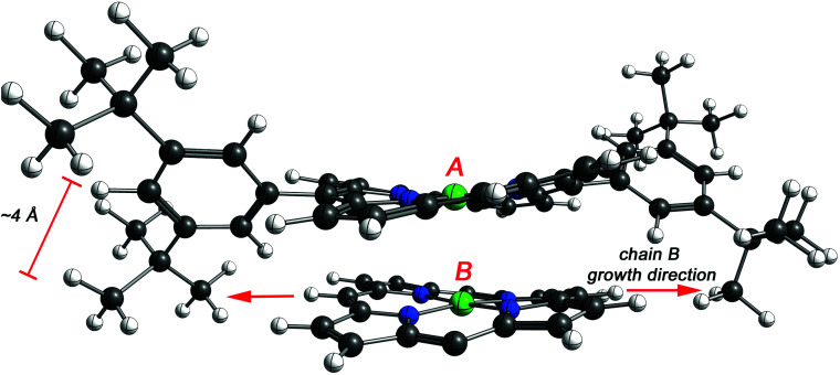
To assess the effect of the cyclization, the distance between the porphyrins plane was estimated by DFT for NiDPP, NiDt-BuPP and their respective fused counterparts (details in ESI†). The estimated distance between the porphyrinic units are 3.39 Å ± 0.2 (NiDPP), 3.30 Å ± 0.1 (NiDPP-4H), 3.44 Å ± 0.2 (NiDt-BuPP) 3.26 Å ± 0.02 (NiDt-BuPP-4H), which are in good agreement with the experimental data obtained by Ishizuka and Kojima.55 However, this small model doesn't take into account that advancing polymerization causes an overlap between the growing chain and the substituents on the surrounding porphyrin chains (Fig. 9). Particularly, the di(tert-butyl)phenyl and mesityl substituents point out of the porphyrin plane by ca. 4 and 3.5 Å, respectively (see NiDt-BuPP example in Fig. 9). Contrarily, in NiDt-BuPP-4H, thanks to the ring fusion forcing the co-planarity of the phenyl rings to the plane, the di(tert-butyl)phenyl groups point out of the plane by only ∼2 Å (Fig. S21†). Since the size of the groups exceeds the average distance between the porphyrins calculated in the small model (3.4–3.2 Å), it can be speculated that the intermolecular distance in the polymeric structure will increase. For example, in NiDt-BuPP, the offset arrangements between the porphyrins yield substituents hindering the growth of the neighbouring porphyrin tape chain (Fig. 9).
Fig. 9. DFT model of two NiDt-BuPP porphyrins (indicated with A and B). 3,5-Di(tert-butyl)phenyl substituents of porphyrin B are omitted for clarity. The tert-butyl groups of porphyrin A point out of the porphyrin plane hindering the growth reaction of porphyrin B.
This likely causes an increase of the interplanar distances for porphyrin tapes not undergoing cyclization. On the other hand, ring fusion flattens the porphyrins minimizing this effect. Considering the ring fusion, the interplanar distance between the units increases in the following order: NiDPP < NiDt-BuPP < NiDMP < NiDDOPP in the oCVD coatings. The different conductivity observed is then related to increasing interchain distances hindering the electron transport process in the material. All the experiments strongly point towards the advantages of the oCVD of porphyrins for the integration into devices of porphyrin tapes. Particularly, the technique allows the synthesis of conjugated porphyrins tapes without any solubilizing agent on the molecule, which is crucial to ensure more compact arrangements that improve the electron transfer and the conductivity in the coatings. This is particularly true for NiDPP. In fact, solution based approaches induce low polymerisation yields, solely forming short oligomers, which are insoluble over five repetitive units.66 On the other hand, the oCVD approach directly yields smooth coatings that, thanks to a completely flat structure, exhibit the best performances in the studied series.
Conclusions
In conclusion, we demonstrated that unlike solution-based approaches, oCVD does not require specific solubilizing substituents attached to the porphyrin to form fused porphyrin tapes. Thin films of fused porphyrin tapes were readily obtained from nickel(ii) porphyrins bearing phenyl, mesityl, di(tert-butyl)phenyl or di(alkoxy)phenyl meso-substituents, overcoming the difficulties related to the processability these materials into advanced devices. The decoupling of the porphyrin substituents from the synthesis requirement allows the formation of dense and homogeneous thin films with conductivity as high as 0.7 S cm−1 for the oCVD coatings prepared from NiDPP. The substituent size was shown to severely affect the arrangement of the molecules and consequently the conductivity of the oCVD films. Large substituents increase the intermolecular distance, weakening the π–π interactions and hindering the interchain electron transfer. This effect highlights a main advantage of the oCVD of porphyrins that allows obtaining porphyrin tapes starting from porphyrins with small substituents. Furthermore, the oCVD approach causes a cyclization between meso-phenyl rings and porphyrin macrocycle improving the electrical performance of the material thanks to enhanced π–π interactions (molecular flattening effect). Nonetheless, it is possible to use the free meso-positions on the porphyrins to increase the functionality of the material. Furthermore, we undoubtedly demonstrated that the formation of β–β/meso–meso/β–β triply linked nickel porphyrins is possible by oCVD.
Experimental section
Experimental procedures, cyclic voltammograms, I–V curves, HIM, AFM images, DFT calculations, extracted ion chromatograms and TGA are provided in the ESI†
Conflicts of interest
There are no conflicts to declare.
Supplementary Material
Acknowledgments
We gratefully acknowledge the financial support of the Luxembourgish “Fonds National de la Recherche” through the CORE project POLYPORPH (C15/MS/10340560/POLYPORH/Boscher). Parts of this research were conducted using the supercomputer Mogon and advisory services offered by Johannes Gutenberg University Mainz (http://www.hpc.uni-mainz.de), which is a member of the AHRP and the Gauss Alliance e. V.
Electronic supplementary information (ESI) available. See DOI: 10.1039/c9ra09711b
References
- Rybicka-Jasińska K. Shan W. Zawada K. Kadish K. M. Gryko D. J. Am. Chem. Soc. 2016;138:15451–15458. doi: 10.1021/jacs.6b09036. [DOI] [PubMed] [Google Scholar]
- Ladomenou K. Natali M. Iengo E. Charalampidis G. Scandola F. Coutsolelos A. G. Coord. Chem. Rev. 2015;304–305:38–54. doi: 10.1016/j.ccr.2014.10.001. [DOI] [Google Scholar]
- Zhao M. Ou S. De Wu C. Acc. Chem. Res. 2014;47:1199–1207. doi: 10.1021/ar400265x. [DOI] [PubMed] [Google Scholar]
- Liu W. Groves J. T. Acc. Chem. Res. 2015;48:1727–1735. doi: 10.1021/acs.accounts.5b00062. [DOI] [PubMed] [Google Scholar]
- Khusnutdinova D. Wadsworth B. L. Flores M. Beiler A. M. Reyes Cruz E. A. Zenkov Y. Moore G. F. ACS Catal. 2018;8:9888–9898. doi: 10.1021/acscatal.8b01776. [DOI] [Google Scholar]
- Rose E. Andrioletti B. Zrig S. Quelquejeu-Ethève M. Chem. Soc. Rev. 2005;34:573–583. doi: 10.1039/B405679P. [DOI] [PubMed] [Google Scholar]
- Zhang W. Lai W. Cao R. Chem. Rev. 2017;117:3717–3797. doi: 10.1021/acs.chemrev.6b00299. [DOI] [PubMed] [Google Scholar]
- Mathew S. Yella A. Gao P. Humphry-Baker R. Curchod B. F. E. Ashari-Astani N. Tavernelli I. Rothlisberger U. Nazeeruddin M. K. Grätzel M. Nat. Chem. 2014;6:242–247. doi: 10.1038/nchem.1861. [DOI] [PubMed] [Google Scholar]
- Li L.-L. Wei-Guang Diau E. Chem. Soc. Rev. 2013;42:291–304. doi: 10.1039/C2CS35257E. [DOI] [PubMed] [Google Scholar]
- Li B. Zheng C. Liu H. Zhu J. Zhang H. Gao D. Huang W. ACS Appl. Mater. Interfaces. 2016;8:27438–27443. doi: 10.1021/acsami.6b10342. [DOI] [PubMed] [Google Scholar]
- Singh S. Aggarwal A. Bhupathiraju N. V. S. D. K. Arianna G. Tiwari K. Drain C. M. Chem. Rev. 2015;115:10261–10306. doi: 10.1021/acs.chemrev.5b00244. [DOI] [PMC free article] [PubMed] [Google Scholar]
- Ethirajan M. Chen Y. Joshi P. Pandey R. K. Chem. Soc. Rev. 2011;40:340–362. doi: 10.1039/B915149B. [DOI] [PubMed] [Google Scholar]
- O'Connor A. E. Gallagher W. M. Byrne A. T. Photochem. Photobiol. 2009;85:1053–1074. doi: 10.1111/j.1751-1097.2009.00585.x. [DOI] [PubMed] [Google Scholar]
- Zhang Y. Lovell J. F. Theranostics. 2012;2:905–915. doi: 10.7150/thno.4908. [DOI] [PMC free article] [PubMed] [Google Scholar]
- Senge M. O. Fazekas M. Notaras E. G. A. Blau W. J. Zawadzka M. Locos O. B. Ni Mhuircheartaigh E. M. Adv. Mater. 2007;19:2737–2774. doi: 10.1002/adma.200601850. [DOI] [Google Scholar]
- Tsuda A. Osuka A. Science. 2001;293:79–82. doi: 10.1126/science.1059552. [DOI] [PubMed] [Google Scholar]
- Anderson H. L. Chem. Commun. 1999:2323–2330. doi: 10.1039/A904209A. [DOI] [Google Scholar]
- Jentzen W. Simpson M. C. Hobbs J. D. Song X. Shelnutt J. A. Ema T. Nelson N. Y. Medforth C. J. Smith K. M. Veyrat M. Mazzanti M. Ramasseul R. Marchon J. C. Takeuchi T. Goddard W. A. J. Am. Chem. Soc. 1995;117:11085–11097. doi: 10.1021/ja00150a008. [DOI] [PubMed] [Google Scholar]
- Jiao C. Zu N. Huang K. W. Wang P. Wu J. Org. Lett. 2011;13:3652–3655. doi: 10.1021/ol201303h. [DOI] [PubMed] [Google Scholar]
- Davis N. K. S. Pawlicki M. Anderson H. L. Org. Lett. 2008;10:3945–3947. doi: 10.1021/ol801500b. [DOI] [PubMed] [Google Scholar]
- Davis N. K. S. Thompson A. L. Anderson H. L. Org. Lett. 2010;12:2124–2127. doi: 10.1021/ol100619p. [DOI] [PubMed] [Google Scholar]
- Banala S. Wurst K. Kräutler B. Chempluschem. 2016;81:477–488. doi: 10.1002/cplu.201600115. [DOI] [PubMed] [Google Scholar]
- Si L. He H. Zhu K. New J. Chem. 2014;38:1565–1572. doi: 10.1039/C3NJ01643A. [DOI] [Google Scholar]
- Kesters J. Verstappen P. Kelchtermans M. Lutsen L. Vanderzande D. Maes W. Adv. Energy Mater. 2015;5:1500218. doi: 10.1002/aenm.201500218. [DOI] [Google Scholar]
- Kim D. Y. Ahn T. K. Kwon J. H. Kim D. Ikeue T. Aratani N. Osuka A. Shigeiwa M. Maeda S. J. Phys. Chem. A. 2005;109:2996–2999. doi: 10.1021/jp050747h. [DOI] [PubMed] [Google Scholar]
- Algethami N. Sadeghi H. Sangtarash S. Lambert C. J. Nano Lett. 2018;18:4482–4486. doi: 10.1021/acs.nanolett.8b01621. [DOI] [PubMed] [Google Scholar]
- Leary E. Limburg B. Alanazy A. Sangtarash S. Grace I. Swada K. Esdaile L. J. Noori M. González M. T. Rubio-Bollinger G. Sadeghi H. Hodgson A. Agraït N. Higgins S. J. Lambert C. J. Anderson H. L. Nichols R. J. J. Am. Chem. Soc. 2018;140:12877–12883. doi: 10.1021/jacs.8b06338. [DOI] [PubMed] [Google Scholar]
- Ha S. Kato K. Sakurai T. Saeki A. Takata M. Uchiyama M. Osuka A. Kim J. Honsho Y. Tashiro K. Aida T. Seki S. Muranaka A. J. Am. Chem. Soc. 2011;133:6537–6540. doi: 10.1021/ja201272t. [DOI] [PubMed] [Google Scholar]
- Yoshida N. Aratani N. Osuka A. Chem. Commun. 2000:197–198. doi: 10.1039/A909444J. [DOI] [Google Scholar]
- Brennan B. J. Kenney M. J. Liddell P. A. Cherry B. R. Li J. Moore A. L. Moore T. A. Gust D. Chem. Commun. 2011;47:10034–10036. doi: 10.1039/C1CC13596A. [DOI] [PubMed] [Google Scholar]
- Brennan B. J. Arero J. Liddell P. A. Moore T. A. Moore A. L. Gust D. J. Porphyrins Phthalocyanines. 2013;17:247–251. doi: 10.1142/S1088424613500363. [DOI] [Google Scholar]
- Feng C.-M. Zhu Y.-Z. Zhang S.-C. Zang Y. Zheng J.-Y. Org. Biomol. Chem. 2015;13:2566–2569. doi: 10.1039/C4OB02644F. [DOI] [PubMed] [Google Scholar]
- Bengasi G. Baba K. Back O. Frache G. Heinze K. Boscher N. D. Chem.–Eur. J. 2019;25:8313–8320. doi: 10.1002/chem.201900793. [DOI] [PMC free article] [PubMed] [Google Scholar]
- Tsuda A. Nakano A. Furuta H. Yamochi H. Osuka A. Angew. Chem., Int. Ed. 2000;39:558–561. doi: 10.1002/(SICI)1521-3773(20000204)39:3<558::AID-ANIE558>3.0.CO;2-G. [DOI] [PubMed] [Google Scholar]
- Tsuda A. Nakamura Y. Osuka A. Chem. Commun. 2003:1096–1097. doi: 10.1039/B302032K. [DOI] [PubMed] [Google Scholar]
- Nakamura Y. Aratani N. Tsuda A. Osuka A. Furukawa K. Kato T. J. Porphyrins Phthalocyanines. 2003;7:264–269. doi: 10.1142/S1088424603000355. [DOI] [Google Scholar]
- Qin H. Li L. Guo F. Su S. Peng J. Cao Y. Peng X. Energy Environ. Sci. 2014;7:1397–1401. doi: 10.1039/C3EE43761B. [DOI] [Google Scholar]
- Bengasi G. Baba K. Frache G. Desport J. Gratia P. Heinze K. Boscher N. D. Angew. Chem., Int. Ed. 2019;58:2103–2108. doi: 10.1002/anie.201814034. [DOI] [PMC free article] [PubMed] [Google Scholar]
- Heydari Gharahcheshmeh M. Gleason K. K. Adv. Mater. Interfaces. 2019;6:1801564. doi: 10.1002/admi.201801564. [DOI] [Google Scholar]
- Wang M. Wang X. Moni P. Liu A. Kim D. H. Jo W. J. Sojoudi H. Gleason K. K. Adv. Mater. 2017;29:1604606. doi: 10.1002/adma.201604606. [DOI] [PMC free article] [PubMed] [Google Scholar]
- Goktas H. Wang X. Boscher N. D. Torosian S. Gleason K. K. J. Mater. Chem. C. 2016;4:3403–3414. doi: 10.1039/C6TC00567E. [DOI] [Google Scholar]
- Goktas H. Wang X. Ugur A. Gleason K. K. Macromol. Rapid Commun. 2015;36:1283–1289. doi: 10.1002/marc.201500069. [DOI] [PubMed] [Google Scholar]
- Lock J. P. Im S. G. Gleason K. K. Macromolecules. 2006;39:5326–5329. doi: 10.1021/ma060113o. [DOI] [Google Scholar]
- Nejati S. Lau K. K. S. Langmuir. 2011;27:15223–15229. doi: 10.1021/la203318f. [DOI] [PubMed] [Google Scholar]
- Kovacik P. del Hierro G. Livernois W. Gleason K. K. Mater. Horiz. 2015;2:221–227. doi: 10.1039/C4MH00222A. [DOI] [Google Scholar]
- Wang X. Ermez S. Goktas H. Gradečak S. Gleason K. K. Macromol. Rapid Commun. 2017;38:1700055. doi: 10.1002/marc.201700055. [DOI] [PubMed] [Google Scholar]
- Wang X. Ugur A. Goktas H. Chen N. Wang M. Lachman N. Kalfon-Cohen E. Fang W. Wardle B. L. Gleason K. K. ACS Sens. 2016;1:374–383. doi: 10.1021/acssensors.5b00208. [DOI] [Google Scholar]
- Wang X. Hou S. Goktas H. Kovacik P. Yaul F. Paidimarri A. Ickes N. Chandrakasan A. Gleason K. K. ACS Appl. Mater. Interfaces. 2015;7:16213–16222. doi: 10.1021/acsami.5b05392. [DOI] [PubMed] [Google Scholar]
- Smolin Y. Y. Van Aken K. L. Boota M. Soroush M. Gogotsi Y. Lau K. K. S. Adv. Mater. Interfaces. 2017;4:1601201. doi: 10.1002/admi.201601201. [DOI] [Google Scholar]
- Nejati S. Minford T. E. Smolin Y. Y. Lau K. K. S. ACS Nano. 2014;8:5413–5422. doi: 10.1021/nn500007c. [DOI] [PubMed] [Google Scholar]
- Fang Y. Koszelewski D. Kadish K. M. Gryko D. T. Chem. Commun. 2014;50:8864–8867. doi: 10.1039/C4CC02759K. [DOI] [PubMed] [Google Scholar]
- Chen P. Fang Y. Kadish K. M. Lewtak J. P. Koszelewski D. Janiga A. Gryko D. T. Inorg. Chem. 2013;52:9532–9538. doi: 10.1021/ic401214e. [DOI] [PubMed] [Google Scholar]
- Lewtak J. P. Koszarna B. Charyton M. K. Gryko D. T. J. Porphyrins Phthalocyanines. doi: 10.1142/S1088424619501530. [DOI] [Google Scholar]
- Baba K. Bengasi G. El Assad D. Grysan P. Lentzen E. Heinze K. Frache G. Boscher N. D. Eur. J. Org. Chem. 2019:2368–2375. doi: 10.1002/ejoc.201900045. [DOI] [Google Scholar]
- Ishizuka T. Saegusa Y. Shiota Y. Ohtake K. Yoshizawa K. Kojima T. Chem. Commun. 2013;49:5939. doi: 10.1039/C3CC42831A. [DOI] [PubMed] [Google Scholar]
- Saegusa Y. Ishizuka T. Komamura K. Shimizu S. Kotani H. Kobayashi N. Kojima T. Phys. Chem. Chem. Phys. 2015;17:15001–15011. doi: 10.1039/C5CP01420D. [DOI] [PubMed] [Google Scholar]
- Wijesekera T. Matsumoto A. Dolphin D. Lexa D. Angew. Chem., Int. Ed. Engl. 1990;29:1028–1030. doi: 10.1002/anie.199010281. [DOI] [Google Scholar]
- Senge M. O. Flögel O. Ruhlandt-Senge K. J. Porphyrins Phthalocyanines. 2001;5:503–506. doi: 10.1002/jpp.353. [DOI] [Google Scholar]
- Schubert M. Franzmann P. Wünsche von Leupoldt A. Koszinowski K. Heinze K. Waldvogel S. R. Angew. Chem., Int. Ed. 2016;55:1156–1159. doi: 10.1002/anie.201508035. [DOI] [PubMed] [Google Scholar]
- Schubert M. Leppin J. Wehming K. Schollmeyer D. Heinze K. Waldvogel S. R. Angew. Chem., Int. Ed. 2014;53:2494–2497. doi: 10.1002/anie.201309287. [DOI] [PubMed] [Google Scholar]
- Leppin J. Schubert M. Waldvogel S. R. Heinze K. Chem.–Eur. J. 2015;21:4229–4232. doi: 10.1002/chem.201406522. [DOI] [PubMed] [Google Scholar]
- Jempty T. C. Gogins K. A. Z. Mazur Y. Miller L. L. J. Org. Chem. 1981;46:4545–4551. doi: 10.1021/jo00335a045. [DOI] [Google Scholar]
- Sarhan A. A. O. Bolm C. Chem. Soc. Rev. 2009;38:2730–2744. doi: 10.1039/B906026J. [DOI] [PubMed] [Google Scholar]
- Burwell R. L. Chem. Rev. 1954;54:615–685. doi: 10.1021/cr60170a003. [DOI] [Google Scholar]
- Lewtak J. P. Gryko D. Bao D. Sebai E. Vakuliuk O. Ścigaj M. Gryko D. T. Org. Biomol. Chem. 2011;9:8178–8181. doi: 10.1039/C1OB06281F. [DOI] [PubMed] [Google Scholar]
- Tsuda A. Nakamura Y. Osuka A. Chem. Commun. 2003:1096–1097. doi: 10.1039/B302032K. [DOI] [PubMed] [Google Scholar]
- In't Veld M. Iavicoli P. Haq S. Amabilino D. B. Raval R. Chem. Commun. 2008:1536–1538. doi: 10.1039/B718865J. [DOI] [PubMed] [Google Scholar]
- Villari V. Mineo P. Scamporrino E. Micali N. Chem. Phys. 2012;409:23–31. doi: 10.1016/j.chemphys.2012.09.022. [DOI] [Google Scholar]
- Yokoyama T. Yokoyama S. Kamikado T. Okuno Y. Mashiko S. Nature. 2001;413:619–621. doi: 10.1038/35098059. [DOI] [PubMed] [Google Scholar]
- Minari T. Seto M. Nemoto T. Isoda S. Tsukagoshi K. Aoyagi Y. Appl. Phys. Lett. 2007;91:123501. doi: 10.1063/1.2786020. [DOI] [Google Scholar]
- Yoon D. H. Lee S. B. Yoo K. H. Kim J. Lim J. K. Aratani N. Tsuda A. Osuka A. Kim D. J. Am. Chem. Soc. 2003;125:11062–11064. doi: 10.1021/ja0346429. [DOI] [PubMed] [Google Scholar]
Associated Data
This section collects any data citations, data availability statements, or supplementary materials included in this article.


