Abstract
The control strategy for the microstructure of resorcinol–furfural (RF) aerogels and derived carbon aerogels is attracting attention in different applications such as adsorbents, electrochemical electrodes, thermal insulation and so on. In this work, RF aerogels with abundant micropores were synthesized successfully by the sol–gel process using resorcinol (R) and furfural (F) as monomers, methanol (M) as the solvent, hexamethylenetetramine (H) as the catalyst, and zinc chloride (Z) as a salt template. The RF aerogels with micro specific surface area up to 228.28 m2 g−1 thus obtained have a high specific surface area (547.96 m2 g−1), and have a large total pore volume (0.7960 cm3 g−1). The carbon aerogels were synthesized by pyrolyzing RF aerogels under a flowing argon atmosphere. Compared with carbon aerogel synthesized without a salt template, carbon aerogels synthesized with a salt template have higher BET specific surface area and larger total pore volume. Moreover, the mean pore size and particle size of carbon aerogels could be greatly reduced by adding the salt template. The influence of M/R ratio (molar ratio of methanol to resorcinol) and Z/R ratio (molar ratio of zinc chloride to resorcinol) on the microstructure of RF aerogels was systematically investigated. The salt templating is an effective approach for controlling the microstructure of RF aerogels and derived carbon aerogels.
The control strategy for the microstructure of resorcinol–furfural (RF) aerogels and derived carbon aerogels is attracting attention in different applications such as adsorbents, electrochemical electrodes, thermal insulation and so on.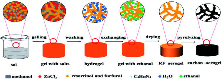
1. Introduction
Resorcinol–formaldehyde aerogel derived from resorcinol and formaldehyde was first reported by Pekala from the Lawrence Livermore National Laboratory in 1989.1,2 The most common RF aerogel is usually synthesized using resorcinol (R) and formaldehyde (F) as monomers, water (W) as a solvent and sodium carbonate (C) as a catalyst.3 RF aerogels are usually used as a pyrolytic precursor to prepare carbon aerogels,2 which are promising materials in the fields of adsorption, catalyst supports, electrochemical electrodes and thermal insulation because of some attractive properties such as a unique microstructure, high specific surface area, excellent electrical conductivity and low thermal conductivity.4–10 The control strategy for the microstructure of resorcinol–furfural (RF) aerogels and derived carbon aerogels is attracting attention in different applications such as adsorbents, thermal insulation and so on.11–15 At present, the microstructure of RF aerogels is mainly controlled by changing the molar ratio of resorcinol to sodium carbonate (R/C ratio) and the molar ratio of water to resorcinol (W/R ratio);15–18 however, the method of controlling the microstructure of RF aerogels has certain limitations. For example, the traditional RF aerogels have few micropores, and the BET specific surface area of RF aerogels is mainly composed of mesoporous and macroporous specific surface area.19 The R/C ratio has a significant effect on the BET specific surface area and particle size of RF aerogels; as the designed molar ratio of R/C values increases, the particle size increases gradually, but the BET specific surface area of RF aerogels decreases gradually.20 The W/R ratio has a small effect on the BET specific surface area and particle size of RF aerogels.20 Therefore, it is a pressing challenge to control the microstructure of RF aerogels and derived carbon aerogels by a simple and effective method.
The porous carbon materials were prepared using glucose as carbon precursor and using eutectics of lithium chloride/zinc chloride as salt template for the first time, appearing as black powder.21–26 Highly porous powder carbons with high specific surface area were obtained using ionic liquids as carbon precursors via salt templating method by Nina Fechler.27 The polymer-derived carbon aerogels were synthesized by direct polymerization of phenol (P) and formaldehyde (F) in the presence of ZnCl2 salts, the PF-ZnCl2 monolith's original volume expands to several times during the carbonization process because ZnCl2 serves as foaming agent and porogens, moreover, this synthesis method required solvothermal polymerization.28 Porous carbon was synthesized using the NaCl as salt template and phenolic resin and pitch as carbon precursors, the porous structure can be modified by changing the mass ratio of NaCl and carbon precursors, the porous carbon also appears as powder.29 We previously reported an exploration of the synthesis parameter space of monolithic hierarchical porous carbon materials with interconnected microstructure by direct polymerization of resorcinol and furfural in isopropanol and using ZnCl2 as salt template, however, the micron-sized pores in the porous carbon are not conducive to thermal insulation.30 Practically, the synthesis of RF aerogels and derived carbon aerogels via salt template method has attracted growing interest, but the research of synthesizing RF aerogels and derived carbon aerogels via salt template is not thorough.31–34
Herein, an effective method, “salt templating”, was applied to control the microstructure of resorcinol–furfural (RF) aerogels and derived carbon aerogels, monolithic RF aerogels with abundant micropores were synthesized successfully by direct polymerization of resorcinol (R) and furfural (F) in methanol (M) using hexamethylenetetramine (HMTA) as catalyst, zinc chloride (Z) as salt template. Zinc chloride could play a key role in forming RF aerogels with abundant micropores, it is acted as dehydration and porogen, it occupies a certain volume in the RF gel, when it was easily washed out with water afterwards, thereby opening up abundant micropores, in order to avoid the collapse of micropores, supercritical drying was adopted in this study, moreover, the micropores of RF aerogels could be well retained during the carbonization process, thus zinc chloride could lead to more micropores and increase the specific surface area of RF aerogel and derived carbon aerogels, abundant micropores will be efficient in reducing the total thermal conductivity by reducing the gaseous thermal conductivity.35 Furthermore, the molar ratio of methanol to resorcinol (M/R) also can control the specific surface area, pore size and particle size of RF aerogels in the presence of zinc chloride. We applied “salt templating” to synthetic RF aerogels and derived carbon aerogels with controllable specific surface area, particle size and pore size, which allows for regulating the internal microstructure of RF aerogels and derived carbon aerogels on nanometer scales and makes them particularly well suited for thermal insulation. To our knowledge, the preparation strategy for RF aerogels and derived carbon aerogels via ZnCl2 salt templating method is very limited and less reported in controlling the microstructure of aerogels.
2. Experimental
2.1. Materials
The resorcinol (R), furfural (F), methanol (M) and zinc chloride (Z) were purchased from Sinopharm Chemical Reagent Co. Ltd and at analytical grade, hexamethylenetetramine (H) was purchased from Tianjin Wind Boat Chemical Reagent Technology Co. LTD and at analytical grade. All of the chemical reagents were used as received without further purification.
2.2. Synthesis of RF aerogels and derived carbon aerogels
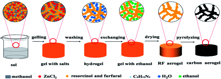
The schematic illustration of synthesizing RF aerogels and carbon aerogels via salt templating method is shown in Fig. 1. Resorcinol–furfural solutions were synthesized by using R and F as monomer, M as solvent, H as catalyst and Z as salt templating. The molar ratio of F/R was 2, the molar ratio of H/R was chosen as 0.024. When four series of RF organic gels with various M/R molar ratios (27.5, 55, 82.5, 110) were synthesized, the molar ratio of Z/R was set to be 6.48, when five series of RF organic gels with various Z/R molar ratios (0, 3.24, 6.47, 9.71, 12.94) were synthesized, the molar ratio of M/R was arranged at 40. After mixing the raw materials thoroughly and magnetically stirring for 30 minutes in a beaker, and the beaker was sealed with plastic film, then put the beaker in an water bath pot, gelled and aged in 50 °C water bath pot. The wet gel with salt templating was soaked in deionized water for 5 days to remove zinc chloride, because RF sol undergoes sufficient chemical cross-linking reactions and transforms into RF gel with high mechanical property after aging treatment, which could resist the damage of water in washing procedure. Then exchanged with ethanol for another 5 days, the deionized water and the ethanol were exchanged one time for everyday. The wet gel were placed in an autoclave and supercritically dried with CO2 (55 °C, 12 MPa), then RF aerogels (Fig. S1a†) were obtained. Finally, carbon aerogels (Fig. S1b†) were synthesized through pyrolyzing the RF aerogels under a flowing argon atmosphere at 900 °C for 1 h (heating rate: 2.5 °C min−1), these carbon aerogels synthesized by various Z/R ratios were correspondingly named as CAS-Z/R-3.24, CAS-Z/R-6.48, CAS-Z/R-9.71 and CAS-Z/R-12.94, respectively.
Fig. 1. Illustration of the synthesis process of RF and derived carbon aerogels via salt templating method.
2.3. Characterizations
The radial linear shrinkage rate (Lshri) of the samples was calculated according to eqn (1), Dbefore and Dafter refer to the diameters of the samples before and after supercritical drying or carbonization process.
 |
1 |
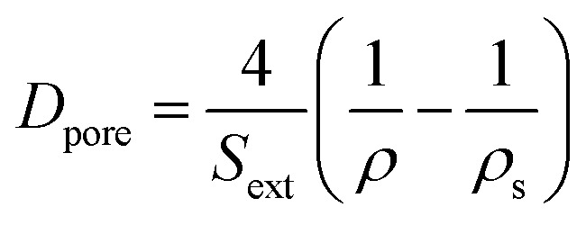
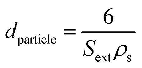
The external surface area Sext (i.e. surface area included mesopore and macropore) was calculated by t-plot method. The mean pore diameter (Dpore) was calculated according to eqn (2),36 and the mean particle diameter (dparticle) was calculated according to eqn (3)36
 |
2 |
 |
3 |
ρ is the bulk density of the aerogel samples, and ρs is the intrinsic density of the backbone particles which formed the network of the aerogels, ρs = 1400 kg m−3. The bulk densities of the RF aerogels and related carbon aerogels were obtained by measuring the volumes and the weights with a vernier caliper and electronic balance. The microstructure was characterized through a 3H-2000PM2 apparatus from BeiShiDe Instrument, the Brunauer–Emmett–Teller (BET) method was utilized to calculate the specific surface areas. The micropores surface area were determined by the t-plot method, the external surface area is the BET specific surface area minus the micropore specific surface area. The total pore volumes were calculated from the adsorption–desorption isotherms using the Barrett–Joyner–Halenda (BJH) model. Pore size distribution curves were obtained by the BJH method from desorption branch of the isotherms. Micropore size distribution of the samples were analyzed by H–K (Horvath–Kawazoe) theory. The microstructural images of the aerogels were investigated by A Hitachi S-4800 scanning electron microscopy, aerogels were sputter coated with a gold alloy to increase their electrical conductivity prior to investigating. The microstructure surface of the obtained aerogels were investigated using Tecnai G2 F20 S-TWIN Field emission transmission electron microscope (TEM) system, the aerogels were ground and dispersed with ethanol before placing it on a copper grid and analyzing it at 300 kV. The chemical elements were analysed using X-ray photoemission spectroscopy (XPS; TESCALAB 250Xi). The crystal phase structures of RF gel with salt template and carbon aerogel were characterized by a D8 Advance X-ray diffraction (XRD) apparatus using Cu Kα radiation with a Ni filter. Raman spectroscopy (Renishaw RM2000) were used to examine the graphitization degree of the carbon aerogels synthesized by salt template. The weight change of RF aerogel during heat treatment were investigated by thermogravimetric analysis and differential scanning calorimetry (TG-DSC, Model STA 449F3, Netzsch) simultaneously in argon atmosphere.
3. Results and discussion
3.1. The effect of methanol on RF aerogels and carbon aerogels
3.1.1. Shrinkage feature
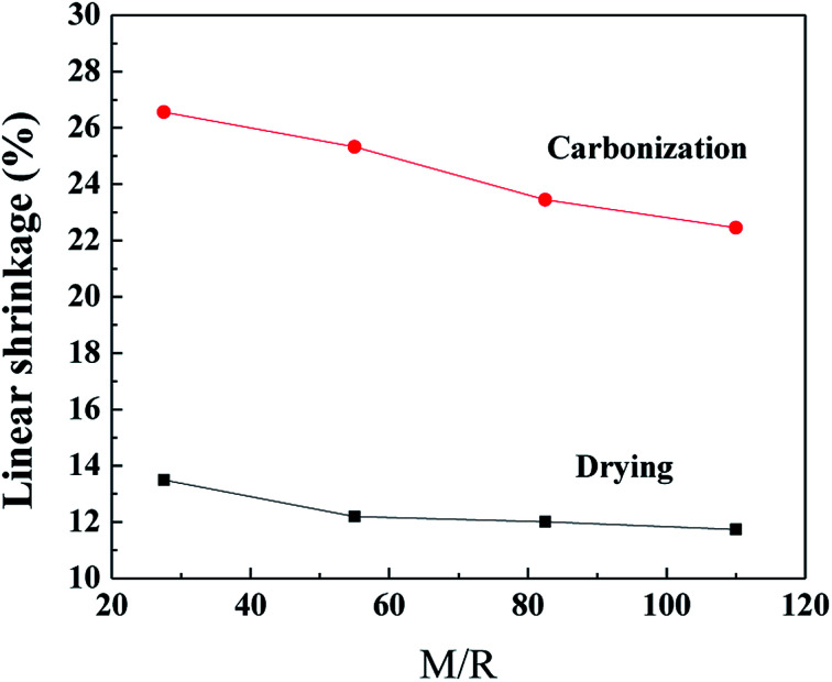
The linear shrinkage of the samples synthesized by various M/R ratios during the supercritical drying and the carbonization process are shown in Fig. 2, the Z/R ratio is kept constant as 6.48. As the molar ratio of M/R increases from 27.5 to 110, the linear shrinkage of the samples gradually decrease from 13.5% to 11.74% during the supercritical drying process, which indicates the linear shrinkage of the samples are not affected evidently by the M/R ratios. The supercritical drying process effectively avoid the capillary tension in the microstructure37 and thus can reduce the shrinkage of the RF aerogels. Compared with the drying process, the linear shrinkage during carbonization is much higher, and gradually decreases from 26.56% to 22.45% with increasing the M/R ratios from 27.5 to 110.
Fig. 2. The linear shrinkage of the aerogels synthesized by various M/R ratios during the CO2 supercritical drying and the carbonization process. The Z/R ratio is kept constant as 6.48.
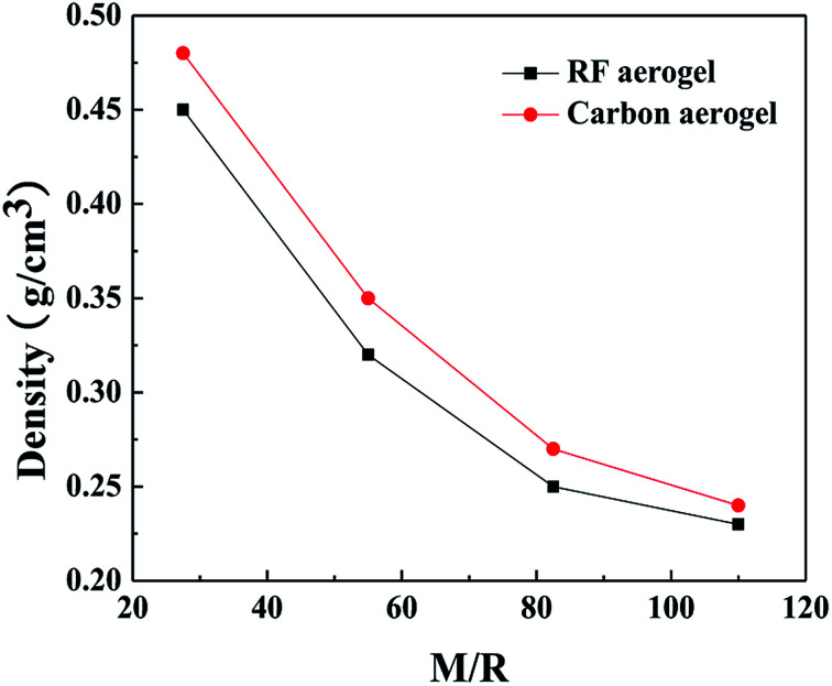
The densities of the RF aerogels and their related carbon aerogels are shown in Fig. 3. As the molar ratio of M/R increases from 27.5 to 110, the densities of the RF aerogels and their related carbon aerogels all gradually decrease. Because the methanol is acted as a solvent, it can dilute the reactant concentration and facilitate the formation of a more loose three-dimensional network structure between the colloidal particles, and it occupies the pore space among the colloidal particles in the wet gel. After washing salt with water, solvent exchange and supercritical drying, methanol will be replaced by air during the supercritical drying process. The higher the M/R ratios, the more pore voids in the wet gel and thus the lower density of the aerogels.
Fig. 3. The densities of the RF aerogels and their related carbon aerogels synthesized by various M/R ratios. The Z/R ratio is kept constant as 6.48.
3.1.2. Pore structure of RF aerogels
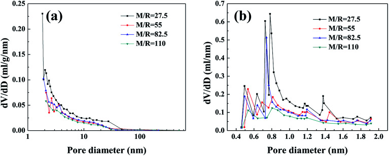
The nitrogen sorption isotherms (Fig. S2†) and pore size distribution curves (Fig. 4) are used to analyze the microstructure of the RF aerogels synthesized by various M/R ratios. According to classification of IUPAC, the RF aerogels synthesized by various M/R ratios exhibit a typical feature of type-IV isotherm,38 which indicates the existence of well-developed nanoporous microstructure. The sharp rise at the initial region of the isotherms (P/P0 ≤ 0.01) is indicative of the presence of micropores in RF aerogels. At the high relative pressure (P/P0 > 0.6), all the samples have an obvious hysteresis loop shape, which is the evidence of the presence of mesopores in RF aerogels.39 BJH pore size distribution curves calculated from the desorption branches of isotherms (Fig. 4a) also confirm that they are mesoporous. From the whole micropore size distribution curves (Fig. 4b), there are abundant micropores in RF aerogels synthesized by various M/R ratios.
Fig. 4. BJH pore size distribution (a) and H–K micropore pore size distribution curves (b) of the RF aerogels synthesized by various M/R ratios. The Z/R ratio is kept constant as 6.48.
The textural properties of the RF aerogels with different molar ratios of M/R are shown in Table 1. The M/R ratio has a great influence on the specific surface area of RF aerogels in the presence of ZnCl2 salt, as the molar ratio of M/R increases from 27.5 to 110, the specific surface area of RF aerogels gradually decreases from 519.57 to 256.88 m2 g−1, micro specific surface area gradually decreases, the results on external specific surface area also gradually decreases, the reduction of specific surface area of RF aerogels is mainly attributed to the difficult formation of nanoporous structure. The mean pore size of the RF aerogel increases from 16 to 74 nm, the mean particle size also increases from 11.6 to 21.7 nm, and the total pore volume of the RF aerogels decreases from 0.8964 to 0.4136 cm3 g−1, as the M/R ratio increases from 27.5 to 110.
The textural properties of the RF aerogel synthesized by various M/R ratiosa.
| M/R | S BET (m2 g−1) | S micro (m2 g−1) | S ext (m2 g−1) | V pore (cm3 g−1) | D pore (nm) | d particle (nm) |
|---|---|---|---|---|---|---|
| 27.5 | 519.57 | 151.47 | 368.10 | 0.8964 | 16 | 11.6 |
| 55 | 355.37 | 127.40 | 242.55 | 0.5306 | 40 | 17.7 |
| 82.5 | 338.45 | 95.90 | 227.97 | 0.4956 | 58 | 18.8 |
| 110 | 256.88 | 59.40 | 197.48 | 0.4136 | 74 | 21.7 |
The Z/R ratio is kept constant as 6.48.
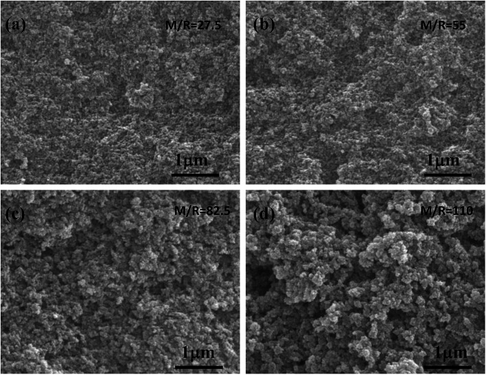
The SEM images of the RF aerogel with various molar ratios of M/R are shown in Fig. 5. From Fig. 5a–d, it can be seen that the synthesized RF aerogel possess a typical three-dimensional microstructure formed by the interconnected nanoparticles. From the SEM photographs, the RF aerogels synthesized by high M/R ratio has a looser structure, the pore size is larger than that with low M/R ratio, and the particle size which formed the network is larger than that with low M/R ratio, because methanol is acted as a solvent, it can dilute the concentration of the reactants and facilitate the formation of a more loose three-dimensional network structure between particles, thus methanol in the solution of the sol–gel process not only adjusts the porosity of the RF aerogel but also adjusts the particle size.
Fig. 5. The SEM images of the RF aerogels synthesized by various M/R ratios: (a) 27.5 (b) 55 (c) 82.5 (d) 110. The Z/R ratio is kept constant as 6.48.
3.2. The effect of zinc chloride on RF aerogels and carbon aerogels
3.2.1. Shrinkage feature
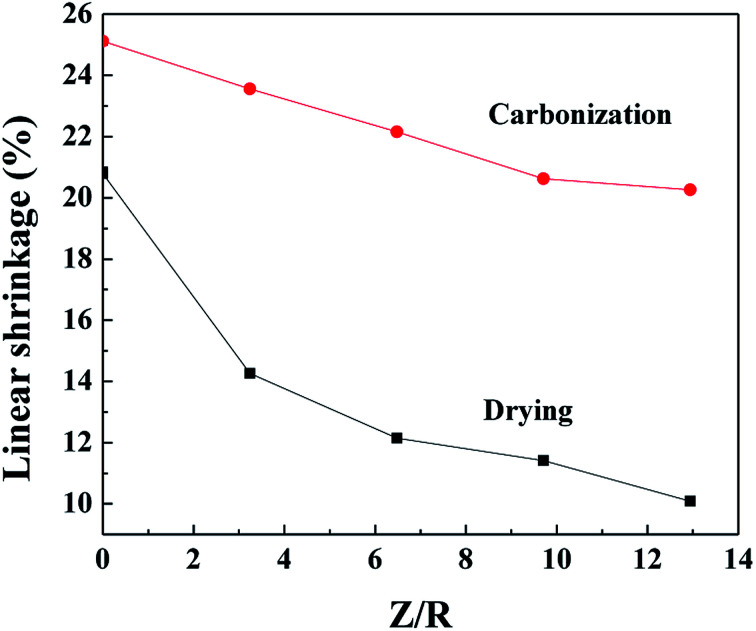
The linear shrinkage of the samples synthesized by various Z/R ratios during the supercritical drying and the carbonization process are shown in Fig. 6. The shrinkage all decrease with increasing the Z/R ratio. The linear shrinkage of the samples prepared without salt template are approximately 20.8% and 25.1% during the supercritical drying and the carbonization process, respectively. Compared with the drying process, the linear shrinkage during carbonization is much higher, and gradually decreases from 24.56% to 20.26% with increasing the Z/R ratios from 3.24 to 12.94.
Fig. 6. The linear shrinkage of the aerogels synthesized by various Z/R ratios during the CO2 supercritical drying and the carbonization process. The M/R ratio is kept constant as 40.
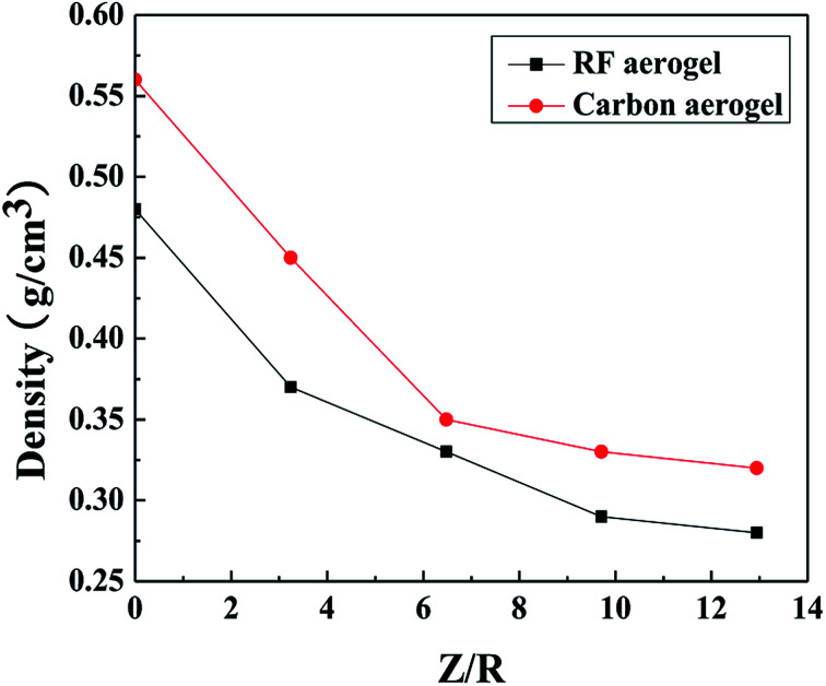
The densities of the RF and carbon aerogels synthesized with various Z/R ratios are shown in Fig. 7. The density of the carbon aerogels is higher than that of its related RF aerogels because of the higher linear shrinkage of the aerogels during carbonization. As the molar ratio of Z/R increases from 3.24 to 12.94, the densities of the RF aerogels and their related carbon aerogels all gradually decrease, when the Z/R ratio is higher than 6.48, the densities of the RF aerogels and their related carbon aerogels all decline mildly. The density of the samples prepared without salt template are approximately 0.48 g cm−3 and 0.56 g cm−3 during the supercritical drying and the carbonization process, respectively.
Fig. 7. The densities of the RF aerogels and carbon aerogels synthesized by various Z/R ratios. The M/R is kept constant as 40.
3.2.2. Pore structure
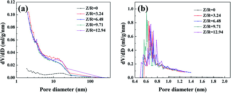
The nitrogen sorption isotherms of the RF aerogels with various Z/R ratios are shown in Fig. S3.† The RF aerogels synthesized with different Z/R ratios present a typical feature of IUPAC type-IV adsorption isotherm,38 the trend of these four sorption isotherms is similar, indicating that they have similar pore structure. For the RF aerogels synthesized by various Z/R ratios, the initial region of the isotherms (P/P0 ≤ 0.01) experience a sharp rise which is indicative of micropores in the samples, the hysteresis loop in the high relative pressure (P/P0 > 0.6) is indicative of mesoporosity in the structure of RF aerogels in addition to the presence of micropores. From the nitrogen sorption isotherm of the RF aerogel synthesized without salt template, the gentle rise of the adsorption curve in the low pressure area indicates that the RF aerogel synthesized without salt template have few micropores, the hysteresis loop in the high relative pressure (P/P0 > 0.6) indicates the presence of mesoporous. BJH pore size distribution curves (Fig. 8a) calculated from the desorption branches of isotherms also confirm that all the RF aerogels have mesopores, the pore size distribution curves of the RF aerogels synthesized with salt template are similar. From the H–K micropore pore size distribution curves (Fig. 8b), there are abundant micropores in RF aerogels synthesized by salt template, the peak value are concentrated between 0.6 and 0.8 nm, however, the RF aerogel synthesized without salt template has few micropores.
Fig. 8. The BJH pore size distribution curves (a) and H–K micropore pore size distribution curves (b) of RF aerogels synthesized by various Z/R ratios. The M/R ratio is kept constant as 40.
The textural properties of RF aerogels synthesized by various Z/R ratios are collected in Table 2. With the designed molar ratio of Z/R values increasing from 3.24 to 12.94, the BET specific surface area of RF aerogel gradually increases from 472.31 to 547.96 m2 g−1, micro specific surface area also gradually increases from 130.43 to 228.28 m2 g−1, the increase in specific surface area is mainly attributed to the formation of more micropores (pore size smaller than 2 nm), because zinc chloride occupies certain pore space between the colloidal particles during the gelation process, after washing salt with water, solvent exchange and supercritical drying, a number of micropores are formed in the RF aerogels. Which indicates zinc chloride could exert the porogen role in the gelling processes, eventually resulting in higher nanoporosity in the RF aerogels. The change rule of total pore volume is similar to the results on external specific surface area, none of them changed significantly. The mean pore size of the RF aerogel increases from 23 to 36 nm, but there is no significant change in the mean particle size, as the Z/R ratio increases from 3.24 to 12.94. From the Table 2, the Z/R ratio has a great influence on the micropores of the RF aerogels, but little influence on the mesoporous and macroporous of the RF aerogels. If ZnCl2 is not added to the sol, the BET specific surface area of the RF aerogel synthesized without salt template is down to 59.84 m2 g−1. Compared with the RF aerogels synthesized by salt template, the total pore volume (0.1883 cm3 g−1) of the RF aerogels synthesized without salt template is very low, but the mean pore size and the mean particle size of the RF aerogels synthesized without salt template are much larger. The results above show that ZnCl2 indeed has a critical effect on the formation of RF aerogels with abundant micropores.
The textural properties of the RF aerogels synthesized by various Z/R ratiosa.
| Z/R | S BET (m2 g−1) | S micro (m2 g−1) | S ext (m2 g−1) | V pore (cm3 g−1) | D pore (nm) | d particle (nm) |
|---|---|---|---|---|---|---|
| 0 | 59.84 | 6.34 | 53.50 | 0.1883 | 102 | 80.1 |
| 3.24 | 472.31 | 130.43 | 341.88 | 0.7815 | 23 | 12.5 |
| 6.48 | 487.78 | 172.45 | 315.33 | 0.7096 | 29 | 13.6 |
| 9.71 | 492.60 | 184.85 | 307.76 | 0.7080 | 33 | 13.9 |
| 12.94 | 547.96 | 228.28 | 319.68 | 0.7960 | 36 | 13.4 |
The M/R ratio is kept constant as 40.
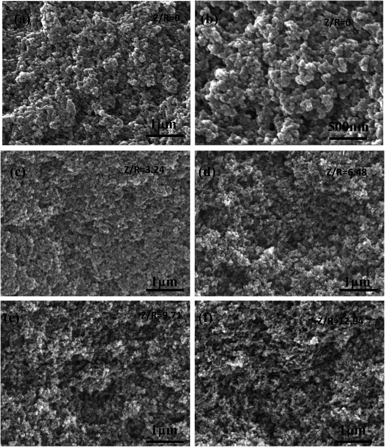
The SEM images of the RF aerogels synthesized by various Z/R ratios are shown in Fig. 9 (M/R ratio is 40). It can be seen that the RF aerogels synthesized by various Z/R were composed of interconnected skeleton particles and there was no obvious pores collapse or particle reunion phenomenon. The pore size and particle size of RF aerogels synthesized without salt template were much larger than those synthesized with salt template. The number of nanopores in the RF aerogels increased obviously, but the particle size of the RF aerogels did not change significantly, with increasing the Z/R molar ratios from 3.24 to 12.94, which is consistent with the results shown in Table 2.
Fig. 9. The SEM images of the RF aerogels synthesized by various Z/R ratios: (a) and (b) 0, (c) 3.24, (d) 6.48, (e) 9.71, (f) 12.94. The M/R ratio is kept constant as 40.
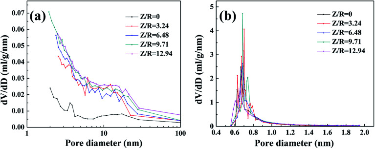
The nitrogen sorption isotherms and the pore size distribution of the carbon aerogels synthesized with various Z/R ratios are shown in Fig. S4.† A sharp rise of the N2 isotherm of all carbon aerogels synthesized with various Z/R ratios at low relative pressure region (P/P0 ≤ 0.01) indicates the presence of micropores in large quantities. For all the carbon aerogels synthesized with or without salt template, the hysteresis loop in high relative pressure scope (P/P0 > 0.7) indicates the presence of mesoporous. The BJH pore size distribution curves (Fig. 10a) indicate that the carbon aerogels synthesized with various Z/R ratios are mainly composed of mesopores. From the H–K micropore pore size distribution curves in Fig. 10b, there are abundant micropores in the carbon aerogels synthesized with or without salt template, the peak value are concentrated about 0.7 nm.
Fig. 10. The BJH pore size distribution curves (a) and H–K micropore pore size distribution curves (b) of carbon aerogels synthesized by various Z/R ratios. The M/R ratio is kept constant as 40.
The textural properties of the carbon aerogels synthesized by various Z/R ratios are collected in Table 3. With the designed molar ratio of Z/R values increasing from 3.24 to 12.94, the BET specific surface area of the carbon aerogels synthesized with salt template initially increases and then decreases, the micro specific surface area also initially increases and then reduces, because excessive salt template results in the damage of micropores. The external specific surface area increases from 225.10 m2 g−1 to 292.59 m2 g−1, and the total pore volume also increases from 0.6666 cm3 g−1 to 0.9573 cm3 g−1 gradually, the mean pore size varies from 24 nm to 35 nm, the mean particle size varies little, as the Z/R ratio increases from 3.24 to 12.94. The increasing in BET specific surface area of carbon aerogels compared with original RF aerogels is attributed to the formation of many micropores in the skeleton particles, which is shown in Fig. S5,† due to the release of small molecules of gas from skeleton particles during the carbonization process. In addition, the original micropores formed by salt templates can be well retained during the carbonization process. Compared with the carbon aerogel synthesized without salt template, the carbon aerogels synthesized with salt template have a higher BET specific surface area, and have a larger total pore volume. Moreover, the mean pore size and particle size of carbon aerogel can be greatly reduced by adding salt template, which is beneficial to restrain the gaseous thermal convection of carbon aerogel.
The textural properties of the carbon aerogels synthesized by various Z/R ratios.
| Z/R | S BET (m2 g−1) | S micro (m2 g−1) | S ext (m2 g−1) | V pore (cm3 g−1) | D pore (nm) | d particle (nm) |
|---|---|---|---|---|---|---|
| 0 | 611.67 | 550.35 | 61.33 | 0.4714 | 70 | 69.9 |
| 3.24 | 730.91 | 505.82 | 225.10 | 0.6666 | 24 | 16.8 |
| 6.48 | 791.07 | 547.99 | 243.09 | 0.8109 | 35 | 17.6 |
| 9.71 | 861.47 | 582.84 | 278.63 | 0.9278 | 33 | 15.4 |
| 12.94 | 743.70 | 451.11 | 292.59 | 0.9573 | 33 | 14.6 |
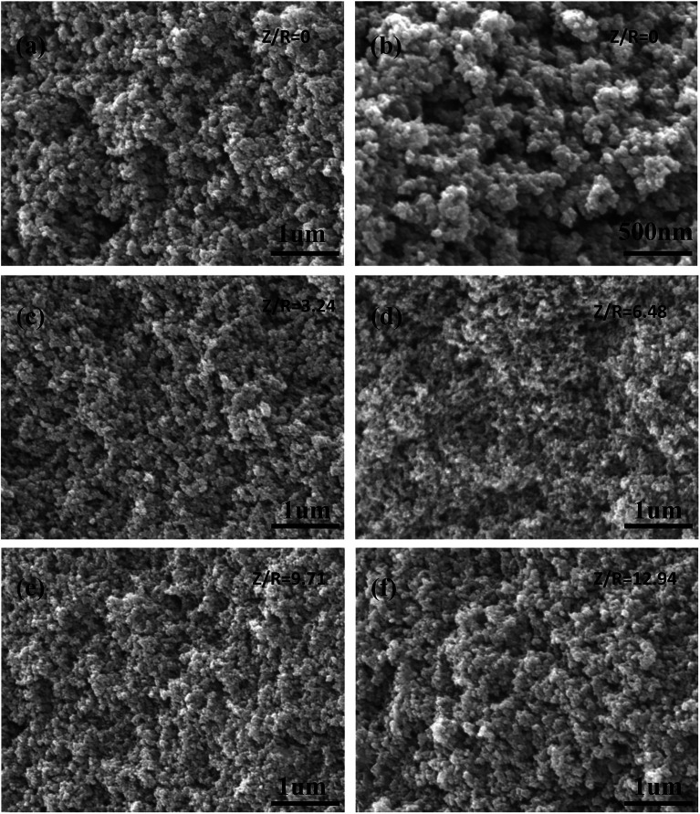
The SEM images of the carbon aerogels synthesized by various Z/R ratios are shown in Fig. 11 (M/R ratio is 40). It can be seen that all carbon aerogels have a three-dimensional network structure, the pore size and particle size of carbon aerogels synthesized with salt template are similar, while the pore size and particle size of carbon aerogel synthesized without salt template were much larger than those synthesized with salt template, which is consistent with the results shown in Table 3.
Fig. 11. The SEM images of the carbon aerogels synthesized by various Z/R ratios: (a) and (b) 0, (c) 3.24, (d) 6.48, (e) 9.71, (f) 12.94. The M/R ratio is kept constant as 40.
TEM observations [see Fig. 12a and b] showed that RF aerogel and carbon aerogel synthesized without salt template have an interconnected nanoporous structure, but the structure of nanoporous network is not obvious, the solid phase is composed of interconnected particles about 70 nm in diameter, the pore size is smaller than 80 nm. The TEM micrographs of the RF aerogel and carbon aerogel synthesized with salt template (Z/R = 6.48) are shown in Fig. 12c and d, they have a similar three-dimension network structure, the structure of nanoporous network is obvious, the solid phase is composed of interconnected particles about 17 nm in diameter, the pore size is smaller than 40 nm which is consistent with the results obtained from nitrogen adsorption analysis.
Fig. 12. TEM micrographs of typical RF aerogel (a) and carbon aerogel (b) synthesized without salt template, TEM micrographs of typical RF aerogel (c) and carbon aerogel (d) synthesized with salt template (Z/R = 6.48).
3.3. Raman and XRD characterization
The graphitization degrees of carbon aerogels were further characterized by Raman spectroscopy. In the Raman spectra (Fig. S6†), two typical peaks at around 1360 cm−1 and 1590 cm−1 are observed, matching with the disordered structure (D-band) and graphitic structure (G-band) of carbon aerogels, respectively.40 A large ID/IG value indicate high amorphization and also signify low graphitisation. With the increase in Z/R ratio, the ID/IG values (1.027, 1.025, 1.028 and 1.021 for CAS-Z/R-3.24, CAS-Z/R-6.48, CAS-Z/R-9.71 and CAS-Z/R-12.94, respectively) hardly changed, indicating that the degree of graphitization did not change with the increase of Z/R ratio. X-ray diffraction pattern of carbon aerogel was shown in Fig. S7.† There are not any sharp peaks and this indicates that carbon aerogel was basically amorphous, the two broad peaks in the diffraction patterns are corresponded to slightly disordered graphitic carbon at about 2θ = 23° and 2θ = 44°. X-ray diffraction pattern of RF gel with salt template was shown in Fig. S8.† There were non-sharp peaks and this indicates that RF gel with salt template was partly crystalline with zinc chloride becoming zinc tetrahydrate, its characteristic signal changes from the sharp peak to the flat one. ZnCl2 salt template takes up a certain volume in RF gel in the form of zinc chloride tetrahydrate, after being washed away and supercritical drying, a large number of micropores are remained in the RF aerogel body, which is consistent with the result from the H–K micropore pore size distribution curves (Fig. 8b).
3.4. Chemical composition and elemental content of the carbon aerogels
XPS measurements are used to analyse chemical components of the carbon aerogel. From the XPS spectra (Fig. S9a†), C atoms and O atoms account for 96.54 at% and 2.34 at%, respectively, in the carbon aerogel, and the residual zinc chloride content in carbon aerogel is extremely low (Table 4). According to the C 1s XPS spectra (Fig. S9b†) of the as-prepared carbon aerogel, the peak at 284.8 eV corresponding to carbon functional groups of C–C or C C.41
Elemental percentages of carbon aerogel prepared by salt template.
| Element | C | O | N | Cl | Zn |
|---|---|---|---|---|---|
| Content (at%) | 96.54 | 2.34 | 0.93 | 0.09 | 0.10 |
3.5. Thermal stability of the carbon aerogels
From the TG-DSC curves of RF aerogel in argon atmosphere (Fig. S10†), the weight loss is 62% for all temperatures and times investigated. DSC shows a exothermic peak in the temperature interval of 500–680 °C. The weight loss (13%) which takes place below 200 °C is due to the evaporation of water and ethanol, a larger weight loss (47%) is observed for RF aerogel in the range from 200 to 900 °C, which can be attributed to the pyrolysis of RF aerogel, some gas molecules were released in the pyrolysis process of RF aerogel. A fairly small weight loss (only 2%) is observed in the temperature interval of 900–1200 °C, which indicates that as-prepared carbon aerogel is stable at temperature up to 1200 °C. Among all the aerogels, carbon aerogel has the highest thermal stability and can maintain the nanoporous structure at a high temperature even exceed 2000 °C in an inert atmosphere.42
4. Conclusions
We developed an effective approach to synthesize RF aerogel with abundant micropores depending on the polymerization of resorcinol and furfural in the presence of zinc chloride, zinc chloride plays a critical role in preparing RF aerogels with abundant micropores, serving as dehydration and porogen, which could be easily removed by simple washing with water. The microstructure of RF aerogel and carbon aerogels can be fine-tuned through controlling the molar ratios of M/R or the molar ratios of Z/R in accordance with the desired application, when the molar ratio of F/R was 2, the molar ratio of M/R was set at 40 and the molar ratio of Z/R was arranged at 12.94, the intact and crack-free RF aerogel with a BET specific surface area up to 547.96 m2 g−1 and micro specific surface area up to 228.28 m2 g−1 was synthesized successfully, then the carbon aerogel without cracks can be obtained by pyrolysis at high temperature, the carbon aerogel thus obtained are of high BET specific surface area (743.70 m2 g−1), big micro specific surface area (451.11 m2 g−1), low density (0.32 g cm−3), and have a large total volume (0.9573 cm3 g−1), this unique nanopore structure of as-prepared carbon aerogels, combining with excellent thermal insulation properties and high temperature resistance, makes them to be the promising candidates for extreme applications such as hypersonic vehicles, and space vehicles, which all possesses lightweight, low thermal conductivity and high temperature resistance. It was found that the molar ratio of M/R and the molar ratio of Z/R in the sol–gel process influence the final microstructure of RF aerogels and carbon aerogels, which includes the sizes of the particles and pores, specific surface areas and so on. Compared with the carbon aerogel synthesized without salt template, the carbon aerogels synthesized with salt template have a higher BET specific surface area, and have a larger total pore volume. Moreover, the mean pore size and particle size of carbon aerogel can be greatly reduced by adding salt template. Salt templating offers a novel and effective way to adjust the microstructure of RF aerogels and carbon aerogels.
Conflicts of interest
There are no conflicts to declare.
Supplementary Material
Acknowledgments
The authors sincerely acknowledge the financial support from National Nature Science Foundation of China (51702360).
Electronic supplementary information (ESI) available. See DOI: 10.1039/c9ra00238c
References
- Pekala R. W.. US Pat., 4873218, 1989
- Pekala R. W. J. Mater. Sci. 1989;24:3221–3227. doi: 10.1007/BF01139044. [DOI] [Google Scholar]
- Mojtaba M. Peter J. H. J. Mater. Sci. 2009;44:2705–2713. doi: 10.1007/s10853-009-3355-5. [DOI] [Google Scholar]
- El-Khatat A. Al-Muhtaseb S. Adv. Mater. 2011;23:2887–2903. doi: 10.1002/adma.201100283. [DOI] [PubMed] [Google Scholar]
- Chang Y. Antonietti M. Fellinger T. Angew. Chem., Int. Ed. 2015;54:5507–5512. doi: 10.1002/anie.201411685. [DOI] [PubMed] [Google Scholar]
- Zhang S. Feng J. Feng J. Jiang Y. Ding F. Appl. Surf. Sci. 2018;440:873–879. doi: 10.1016/j.apsusc.2018.01.252. [DOI] [Google Scholar]
- Xin W. Song Y. RSC Adv. 2015;5:83239–83285. doi: 10.1039/C5RA16864C. [DOI] [Google Scholar]
- Balakumara K. Kalaiselvi N. RSC Adv. 2015;5:34008–34018. doi: 10.1039/C5RA01436K. [DOI] [Google Scholar]
- Wang H. Gong Y. Wang Y. RSC Adv. 2014;4:45753–45759. doi: 10.1039/C4RA08446B. [DOI] [Google Scholar]
- Yang X. Du G. Zhang L. Liu Y. Mater. Lett. 2016;183:52–55. doi: 10.1016/j.matlet.2016.07.069. [DOI] [Google Scholar]
- Yu M. Li J. Wang L. Chem. Eng. J. 2017;310:300–306. doi: 10.1016/j.cej.2016.10.121. [DOI] [Google Scholar]
- Yu Y. Wu X. Fang J. J. Mater. Sci. 2015;50:5115–5124. doi: 10.1007/s10853-015-9034-9. [DOI] [Google Scholar]
- Yu M. Han Y. Li J. Wang L. Int. J. Biol. Macromol. 2018;115:185–193. doi: 10.1016/j.ijbiomac.2018.04.012. [DOI] [PubMed] [Google Scholar]
- Zhang J. Chen G. Zhang Q. Kang F. You B. ACS Appl. Mater. Interfaces. 2015;7:12760–12766. doi: 10.1021/acsami.5b01660. [DOI] [PubMed] [Google Scholar]
- Saliger R. Bock V. Petricevic R. Tillotson T. Geis S. Fricke J. J. Non-Cryst. Solids. 1997;221:144–150. doi: 10.1016/S0022-3093(97)00411-0. [DOI] [Google Scholar]
- Horikawa T. Hayashi J. Muroyama K. Carbon. 2004;42:1625–1633. doi: 10.1016/j.carbon.2004.02.016. [DOI] [Google Scholar]
- Bock V. Emmerling A. Fricke J. J. Non-Cryst. Solids. 1998;225:69–73. doi: 10.1016/S0022-3093(98)00060-X. [DOI] [Google Scholar]
- Long D. Liu X. Qiao W. Zhang R. Zhan L. Ling L. J. Non-Cryst. Solids. 2009;355:1252–1258. doi: 10.1016/j.jnoncrysol.2009.04.039. [DOI] [Google Scholar]
- Al-Muhtaseb S. A. Ritter J. A. Adv. Mater. 2003;15:101–114. doi: 10.1002/adma.200390020. [DOI] [Google Scholar]
- Feng J. Feng J. Zhang C. J. Sol-Gel Sci. Technol. 2011;59:371–380. doi: 10.1007/s10971-011-2514-8. [DOI] [Google Scholar]
- Fechler N. Wohlgemuth S. Jaker P. Antonietti M. J. Mater. Chem. A. 2013;1:9418–9421. doi: 10.1039/C3TA10674H. [DOI] [Google Scholar]
- Tang J. Yamauchi Y. Nat. Chem. 2016;8:638–639. doi: 10.1038/nchem.2548. [DOI] [PubMed] [Google Scholar]
- Salunkhe R. R. Young C. Tang J. Takei T. Ide Y. Kobayashi N. Yamauchi Y. Chem. Commun. 2016;52:4764–4767. doi: 10.1039/C6CC00413J. [DOI] [PubMed] [Google Scholar]
- Zhang W. Jiang X. Zhao Y. Carne-Sanchez A. Malgras V. Kim J. Kim J. H. Wang S. Liu J. Jiang J. Yamauchi Y. Hu M. Chem. Sci. 2017;8:3538–3546. doi: 10.1039/C6SC04903F. [DOI] [PMC free article] [PubMed] [Google Scholar]
- Young C. Wang J. Kim J. Sugahara Y. Henzie J. Yamauchi Y. Chem. Mater. 2018;30(10):3379–3386. doi: 10.1021/acs.chemmater.8b00836. [DOI] [Google Scholar]
- Wang C. Kaneti Y. V. Bando Y. Lin J. Liu C. Li J. Yamauchi Y. Mater. Horiz. 2018;5:394–407. doi: 10.1039/C8MH00133B. [DOI] [Google Scholar]
- Fechler N. Fellinger T. Antonietti M. Adv. Mater. 2013;25:75–79. doi: 10.1002/adma.201203422. [DOI] [PubMed] [Google Scholar]
- Yu Z. Li G. Fechler N. Yang N. Ma Z. Wang X. Antonietti M. Yu S. Angew. Chem., Int. Ed. 2016;55:1–6. doi: 10.1002/anie.201510990. [DOI] [Google Scholar]
- Qiu D. Cao T. Zhang J. Zhang S. Zheng D. Wu H. Lv W. Kang F. Yang Q. J. Energy Chem. 2018 doi: 10.1016/j.jechem.2018.05.014. [DOI] [Google Scholar]
- Zhang H. Feng J. Li L. Jiang Y. Feng J. Monatsh. Chem. 2018;149:2137–2144. doi: 10.1007/s00706-018-2285-9. [DOI] [Google Scholar]
- Liu X. Fechler N. Antonietti M. Chem. Soc. Rev. 2013;42:8237–8265. doi: 10.1039/C3CS60159E. [DOI] [PubMed] [Google Scholar]
- Liu X. Antonietti M. Carbon. 2014;69:460–466. doi: 10.1016/j.carbon.2013.12.049. [DOI] [Google Scholar]
- Kong W. Zhao F. Guan H. Zhao Y. Zhang B. J. Mater. Sci. 2016;51:6793–6800. doi: 10.1007/s10853-016-9966-8. [DOI] [Google Scholar]
- Li K. Tang D. Zhang W. Qiao Z. Liu Y. Huo Q. Liang D. Zhu J. Zhao Z. Mater. Lett. 2017;209:256–259. doi: 10.1016/j.matlet.2017.08.021. [DOI] [Google Scholar]
- Feng J. Feng J. Jiang Y. Zhang C. Mater. Lett. 2011;65:3454–3456. doi: 10.1016/j.matlet.2011.07.114. [DOI] [Google Scholar]
- Wiener M. Reichenauer G. Braxmeier S. Hemberger F. Ebert H. P. Int. J. Thermophys. 2009;30:1372–1385. doi: 10.1007/s10765-009-0595-1. [DOI] [Google Scholar]
- Griffin J. S. Mills D. H. Cleary M. Nelson R. Manno V. P. Hodes M. J. Supercrit. Fluids. 2014;94:38–47. doi: 10.1016/j.supflu.2014.05.020. [DOI] [Google Scholar]
- Lin C. Ritter J. A. Carbon. 1997;35:1271–1278. doi: 10.1016/S0008-6223(97)00069-9. [DOI] [Google Scholar]
- Tamon H. Ishizaka H. Mikami M. Okazaki M. Carbon. 1997;35:791–796. doi: 10.1016/S0008-6223(97)00024-9. [DOI] [Google Scholar]
- Wang Y. Alsmeyer D. C. Mccreery R. L. Chem. Mater. 1990;2:557–563. doi: 10.1021/cm00011a018. [DOI] [Google Scholar]
- Yi J. Qing Y. Wu C. Zeng Y. Wu Y. Lu X. Tong Y. J. Power Sources. 2017;351:130–137. doi: 10.1016/j.jpowsour.2017.03.036. [DOI] [Google Scholar]
- Hanzawa Y. Hatori H. Yoshizawa N. Yamada Y. Carbon. 2002;40:575–581. doi: 10.1016/S0008-6223(01)00150-6. [DOI] [Google Scholar]
Associated Data
This section collects any data citations, data availability statements, or supplementary materials included in this article.


