Abstract
Electrochemical oxidation of biomass substrates to valuable bio‐chemicals is highly attractive. However, the design of efficient, selective, stable, and inexpensive electrocatalysts remains challenging. Here it is reported how a 3D highly ordered mesoporous Co3O4/nickel foam (om‐Co3O4/NF) electrode fulfils those criteria in the electrochemical oxidation of 5‐hydroxymethylfurfural (HMF) to value‐added 2,5‐furandicarboxylic acid (FDCA). Full conversion of HMF and an FDCA yield of >99.8 % are achieved with a faradaic efficiency close to 100 % at a potential of 1.457 V vs. reversible hydrogen electrode. Such activity and selectivity to FDCA are attributed to the fast electron transfer, high electrochemical surface area, and reduced charge transfer resistance. More impressively, remarkable catalyst stability under long‐term testing is obtained with 17 catalytic cycles. This work highlights the rational design of metal oxides with ordered meso‐structures for electrochemical biomass conversion.
Keywords: biomass upgrading, electrocatalysis, ordered mesoporous Co3O4 , oxidation, stability.
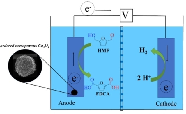
Electrochemical biomass upgrading: Highly ordered mesoporous Co3O4 is an efficient, selective, stable, and inexpensive electrocatalyst for 5‐(hydroxymethyl)furfural (HMF) oxidation, achieving a 2,5‐furandicarboxylic acid (FDCA) yield of >99.8 % with a faradaic efficiency close to 100 %. Remarkable catalyst stability is obtained with 17 catalytic cycles.
Introduction
Since the seminal study by Grabowski et al., [1] electrochemical oxidation of 5‐hydroxymethylfurfural (HMF), one of the top biomass‐derived building block substrates for the production of plastics, pharmaceuticals, and liquid fuels,[ 2 , 3 , 4 , 5 , 6 ] has attracted considerable interest, due to its potential sustainability, ease of operation, and low cost.[ 7 , 8 , 9 ] Moreover, it generates a value‐added product instead of oxygen, if coupled with hydrogen evolution in an electrolyzer. Catalysis efficiency, pH value, and applied potential are playing essential roles in product yield; however, relatively little attention has been paid to catalyst stability. Nevertheless, strategies to improve the performance and stability of the electrocatalytic reaction are highly called for.
Electro‐oxidation of HMF to value‐added 2,5‐furandicarboxylic acid (FDCA), a renewable alternative to petroleum‐based monomeric terephthalic acid to synthesize bio‐based functional polymeric materials,[ 10 , 11 , 12 , 13 ] could offer substantial advantages over thermocatalytic routes in terms of sustainability and cost and has recently been actively studied. For instance, Cha and Choi employed the redox mediator (2,2,6,6‐tetramethylpiperidin‐1‐yl)oxyl (TEMPO) and Au and Pt catalysts for HMF oxidation in a photoelectrochemical cell. [14] Sun and co‐workers showed that Ni‐ and Co‐based sulfides and phosphides are efficient catalysts for electro‐oxidation of HMF, with >98 % yield to FDCA in alkaline condition.[ 15 , 16 , 17 ] Schuhmann and co‐workers reported metal borides to be efficient electrocatalysts for the selective oxidation of HMF to FDCA using a flow reactor.[ 18 , 19 ] Zhang et al. and Li et al. demonstrated the use of metal nitrides, such as Ni3N and VN, to achieve high yields of FDCA by HMF electro‐oxidation.[ 20 , 21 ] Moreover, porous Ni, [22] Ni/Co/Fe oxyhydroxides, [23] nanocrystalline Cu foam, [24] Co based catalysts,[ 25 , 26 ] and NiFe layered double hydroxide [27] are all efficient catalytic systems for electrocatalytic oxidation of HMF to FDCA. The synthesis and use of those catalysts represent a significant improvement over the state of the art. However, one may assume that the catalyst surfaces are likely their oxide/hydroxide counterparts,[ 15 , 16 , 17 , 23 , 24 , 25 , 26 , 27 ] which are most probably the active species during electrochemical HMF oxidation in aqueous environment. It is thus unclear what the long‐term stability of the systems based on non‐oxides would be.
Considering this critical stability issue and taking into account that the electrocatalyst might impose diffusion limitations on the working electrode, [28] an anode catalyst design based on metal oxides with mesoporous nanostructure appeared to be attractive. Ordered mesoporous metal oxides[ 29 , 30 , 31 ] could offer the efficiency, stability, and channel interconnectivity for facile diffusion during electrochemical HMF oxidation. In the following, we report the use of an ordered mesoporous Co3O4 catalyst as a stable electrocatalyst to efficiently and selectively integrate oxidative HMF conversion to FDCA with hydrogen production in a single electrolyzer. Complete HMF conversion, nearly quantitative yield of FDCA, and high faradaic efficiencies (FE) were generally obtained in 1.0 m KOH under ambient conditions, together with satisfactory catalyst stability.
Results and Discussion
Highly ordered mesoporous Co3O4 (om‐Co3O4) was prepared by the nanocasting method[ 32 , 33 , 34 , 35 , 36 ] using KIT‐6 as the template. Cobalt(II) nitrate was initially transformed to a Co3O4/KIT‐6 composite by impregnation with KIT‐6 combined with calcination in air. Subsequently, a 3D ordered mesoporous Co3O4 nanostructure was obtained after etching the KIT‐6 template in hot alkaline solution. For comparison, disordered mesoporous Co3O4 (dm‐Co3O4) was prepared via replicating disordered mesoporous silica template, while bulk Co3O4 was prepared via direct decomposition of cobalt(II) nitrate (see Experimental Section, Supporting Information). The residual silicon content in the templated Co3O4 samples, determined by atomic absorption spectrometry (AAS) analysis, is 0.21 and 0.22 wt % for om‐Co3O4 and dm‐Co3O4, respectively.
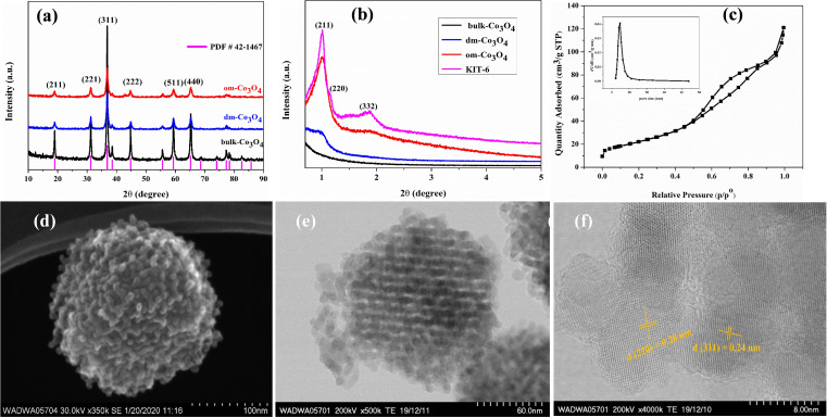
Characterization data of the om‐Co3O4 agree well with previous publications.[ 32 , 33 , 34 , 35 , 36 ] The three Co3O4 catalysts display the typical diffraction peaks of Co3O4 in wide‐angle X‐ray powder diffraction (XRD) that match well with the corresponding standard XRD data (Figure 1a). However, they are clearly distinguished by the small‐angle XRD patterns (Figure 1b). Om‐Co3O4 shows obvious diffraction peaks that are analogous to the mother template KIT‐6 with the known 3D bicontinuous ordered mesostructure, while those characteristic peaks are absent for dm‐Co3O4 and bulk Co3O4 samples (Figure 1b). Om‐Co3O4 exhibits type IV isotherms with a H1‐type hysteresis loop, which is a characteristic feature of mesoporous materials. According to the N2 adsorption isotherm, the Brunauer–Emmett–Teller (BET) surface area is 92 m2 g−1, and the pore volume is 0.19 cm3 g−1 with a narrow pore size distribution at 4.9 nm (Figure 1c).
Figure 1.
Structural characterization of the Co3O4 catalysts. (a) Wide‐angle XRD patterns of the Co3O4 catalysts. (b) Small‐angle XRD patterns of the Co3O4 catalysts and KIT‐6 template. (c) N2 sorption isotherm of om‐Co3O4. Inset: pore size distribution. The increase in amount adsorbed near saturation is attributed to voids caused by unfilled parts of the KIT‐6 template and interparticle voids. (d) SEM image, (e) STEM image, and (f) HRTEM image of om‐Co3O4.
The scanning electron microscopy (SEM) and scanning transmission electron microscope (STEM) images of om‐Co3O4 show a 3D regular grid‐like particle with a size of about 150 nm, representative for the whole sample, further illustrating the successful replication of a highly ordered mesostructured KIT‐6 template (Figure 1d,e). The high‐resolution (HR)TEM image shows lattice spacings of 0.28 and 0.24 nm, corresponding to the (220) and (311) planes of Co3O4, respectively (Figure 1f).
X‐ray photoelectron spectroscopy (XPS) was used to characterize the surface properties of om‐Co3O4 (Figure S9). The binding energies (B.E.) at 779.4 and 794.5 eV are assigned to the surface Co3+ species, and the signals at 781 and 796.3 eV to surface Co2+ species. Moreover, the low‐intensity broad peaks appearing at about 787 and 804 eV, characteristic of the shake‐up satellites of Co3O4,[ 37 , 38 , 39 , 40 ] are also clearly seen. The B.E. at approximately 533–527 eV is characteristic for O1 s. These signals can be assigned to the surface framework oxygen (≈530 eV) and adsorbed oxygen (531–533 eV), respectively.[ 41 , 42 , 43 , 44 ] The full characterization results of the dm‐Co3O4 and bulk Co3O4 catalysts, including the electron microscopy analysis (SEM and TEM), N2 sorption analysis (BET surface areas and pore size distributions), XPS analysis, and the interpretations are shown in the Supporting Information section 2.
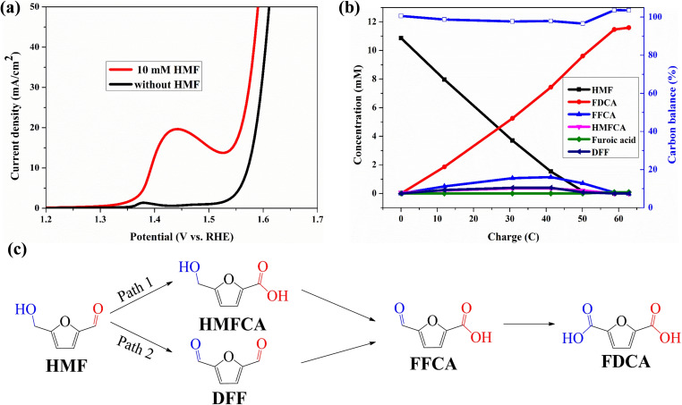
The catalytic performances of the Co3O4 catalysts were evaluated for the electro‐oxidation of HMF in an aqueous electrolyte (1 m KOH), in which the oxygen evolution reaction (OER) is the major competing reaction. First a control experiment was conducted, with only nickel Ni foam (NF) as electrode. In linear sweep voltammetry (LSV) curves, NF shows no obvious oxidation peak for HMF (only the peak attributed to nickel oxidation), but the current density increased after adding 10 mm HMF (Figure S12). The performance of the om‐Co3O4/NF electrode for HMF electro‐oxidation and water oxidation (OER) was then compared by LSV. In the absence of HMF, the LSV curve of the om‐Co3O4/NF electrode shows an obvious Ni2+/Ni3+ oxidation peak, attributed to the surface oxidation of the NF substrate, [28] followed by the decrease of current density to a stable region; finally, at around 1.55 V, the current density significantly increases due to the beginning of OER. The LSV curve of om‐Co3O4/NF reaches a current density of 10 mA cm−2 at a potential of 1.57 V [vs. reversible hydrogen electrode (RHE)]. After adding 10 mm HMF, this potential is considerably reduced to 1.39 V (vs. RHE) to reach the same current density, indicating that om‐Co3O4/NF is capable of catalyzing HMF electro‐oxidation, which proceeds at substantially lower potential than the OER (Figure 2a). Compared to NF, om‐Co3O4/NF shows a much lower onset potential and an obvious increase in current density upon the addition of 10 mm HMF, indicating that the catalytically active sites of om‐Co3O4/NF are distinct from NF.
Figure 2.
(a) LSV curves for om‐Co3O4/NF in 1 m KOH with and without 10 mm HMF. (b) Conversion and concentration changes of HMF and its oxidation products during the electrochemical oxidation of HMF at 1.457 V vs. RHE in 1 m KOH with and without 10 mm HMF. (c) Two possible pathways of HMF oxidation to FDCA.
Constant potential electrolysis at 1.457 V (vs. RHE) coupled with high‐performance liquid chromatography (HPLC) analysis was thus used to monitor the reaction process, to identify and quantify the oxidation products as well as to calculate the FE. The conversion and concentration changes of HMF and its oxidation products during electrolysis are plotted in Figure 2b. The oxidation of HMF to FDCA is a six‐electron transfer process, and for 10 mm HMF (10.86 mm HMF by HPLC) electrolysis, a charge of 62.8 C is required for the full conversion of HMF to FDCA. In the course of the reaction, the concentration of HMF decreases and that of FDCA rises, both linearly, respectively, and the color of the electrolyte changes progressively from light yellow to colorless. After passing a charge of 62.8 C, full HMF conversion was achieved with a high FDCA yield of >99.8 % and an FE of close to 100 %, based on the theoretical charges for the formation of FDCA. In addition, the carbon balance remains >97 % during the reaction (Figure 2b), which is different from previous studies that report a not fully closed carbon balance caused by the formation of humins.[ 45 , 46 ] Our results advantageously compare with examples from the recent literature, as listed in Table 1, in spite of the fact that a high number of active catalysts for the HMF electro‐oxidation reactions are already known. Especially the high efficiency and excellent selectivity of our catalyst for FDCA formation are notable. Oxidation of HMF begins with the oxidation of either aldehyde or hydroxy groups on HMF. The former forms 5‐hydroxymethyl‐2‐furancarboxylic acid (HMFCA) as the intermediate, while the latter forms 2,5‐diformylfuran (DFF) as the intermediate. Then both intermediates are oxidized to 5‐formyl‐2‐furancarboxylic acid (FFCA) prior to the final product FDCA (Figure 2c). In the present case, HMF oxidation catalyzed by om‐Co3O4/NF likely followed both routes, because the HPLC chromatograms taken at various electrolysis charges show the co‐existence of both HMFCA and DFF with similar concentrations.
Table 1.
Examples of recent literature on the HMF electrochemical oxidation to FDCA in alkaline condition.
|
Catalysts |
Oxidation potential [V vs. RHE] (current density [mA cm−2]) |
Conv. [%] |
FDCA Sel. [%] |
FE [%] |
Ref. |
|---|---|---|---|---|---|
|
Ni3S2 |
1.36 (10) |
99.5 |
98 |
98 |
[15] |
|
Ni2P |
1.35 (onset) |
98 |
97 |
97 |
[16] |
|
CoP |
1.38 (10) |
99 |
>90 |
>90 |
[17] |
|
Ni3N@C |
1.38 (50) |
99 |
98 |
≈99 |
[20] |
|
VN |
1.36 (10) |
96 |
94 |
90 |
[21] |
|
hp‐Ni |
1.36 (10) |
– |
98 |
92–98 |
[22] |
|
Ni(OH)2/NiOOH |
1.34 (onset) |
99.8 |
96.0 |
96.0 |
[23] |
|
NiCo2O4 |
1.36 (onset) |
99.6 |
90.8 |
>80 |
[25] |
|
Ni x B |
1.39 (10) |
99.5 |
98.5 |
≈100 |
[28] |
|
N‐Ni3S2‐MoO2 |
1.57 (50) |
96 |
90 |
90 |
[47] |
|
NiSe@NiO x |
1.35 (onset) |
99 |
98 |
98 |
[48] |
|
CuNi(OH)2 |
1.45 (9.2) |
98.8 |
93.3 |
94.4 |
[49] |
|
MoO2‐FeP@C |
1.323 (onset) |
99.4 |
98.6 |
97.8 |
[50] |
|
NiCoFe‐LDH nanosheets |
≈1.51 (20) (at 55 °C) |
≈96 |
≈85 |
≈90 in 1 h |
[51] |
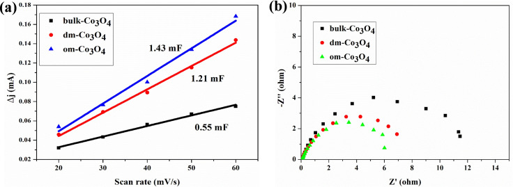
In order to clarify the origin of the high efficiency of the om‐Co3O4/NF, we first measured the double‐layer capacitance (C dl) to estimate the electrochemically active surface area (ESCA). The cyclic voltammograms (CV) in a non‐faradaic potential range of 0.998 to 1.098 V vs. RHE in 1 m KOH with 10 mm HMF are recorded (Figures S15–S17), and the C dl is then calculated as half of the slope of linear fitting between currents at 1.05 V vs. RHE and scan rates. In the presence of 10 mm HMF, the C dl of om‐Co3O4/NF has a higher value than that of dm‐Co3O4/NF and bulk‐Co3O4/NF (Figure 3a), further demonstrating that it provides higher surface roughness and exposes more active sites for HMF electro‐oxidation. [52] We further compare the resistances, determined by electrochemical impedance spectroscopy (EIS) measurements, of the three Co3O4/NF electrodes in the presence of 10 mm HMF in 1 m KOH at 1.517 V to investigate the electrode/electrolyte interface properties (Figure 3b). The fitted charge transfer resistance (R ct) of om‐Co3O4/NF is still the lowest among those Co3O4 catalysts, indicating a more facile electron transfer on the surface of om‐Co3O4 catalyst, [18] which leads to a much faster kinetics for HMF electro‐oxidation. Those data, together with the excellent results obtained in the catalyst recycling tests (see below vide infra), demonstrate the structural and textural advantage of om‐Co3O4 in efficient and selective oxidation of HMF to FDCA, making judiciously chosen mesoporous oxides attractive for oxidative upgrading of biomass. It has been suggested that the real active species for HMF oxidation are metal oxides/hydroxides/oxyhydroxides.[ 15 , 16 , 17 , 23 , 24 , 25 , 26 , 27 ] It is currently not clear whether om‐Co3O4 possesses any intrinsically different active sites compared to other Co‐based electrocatalysts. In order to clarify this, in‐situ characterization under reaction conditions would be required, which is beyond the scope of this study.
Figure 3.
(a) Charging current differences (Δj=j anode−j cathode) plotted against scan rates for three Co3O4 catalysts, and (b) Nyquist plots in the presence of 10 mm HMF at 1.517 V (vs. RHE).
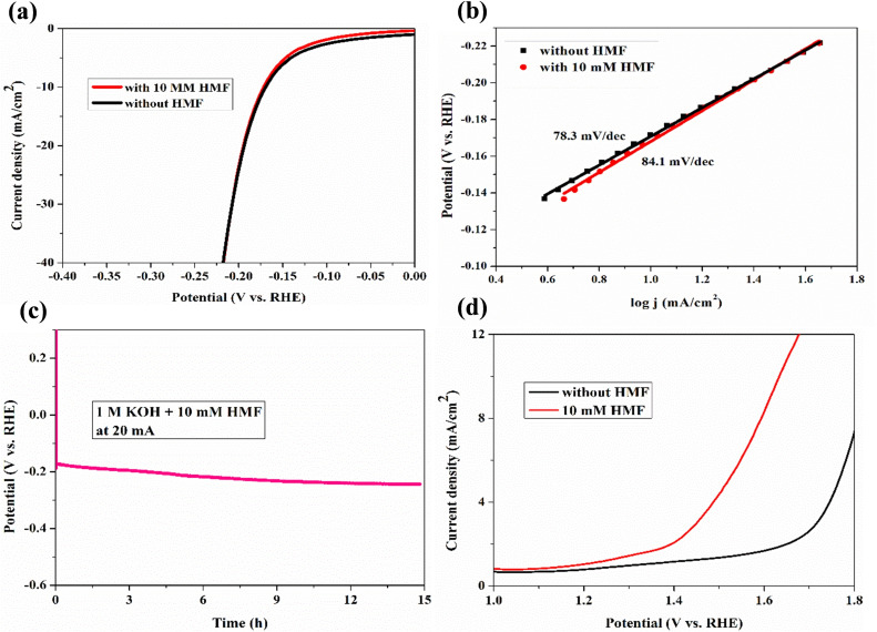
To couple the hydrogen evolution reaction (HER) and HMF oxidation for simultaneous H2 and FDCA production, the electrocatalytic HER performance of the om‐Co3O4/NF was measured. The overpotential of om‐Co3O4/NF does not change significantly in the presence or in the absence of 10 mm HMF (Figure 4a), and the calculated Tafel slope only increases from 78.3 to 84.1 mV dec−1 (Figure 4b). Furthermore, a chronopotentiometry experiment conducted at a current of −20 mA in 1.0 m KOH with 10 mm HMF only shows a slight potential decrease after electrolysis for 15 h (Figure 4c). Altogether, those results unambiguously show that the presence of HMF has no substantial effect on the HER performance; incidentally, also the high stability of the om‐Co3O4/NF electrode under the reaction condition is proven. These results made the assembly of a two‐electrode electrolyzer (om‐Co3O4/NF||om‐Co3O4/NF) for simultaneous FDCA formation and H2 evolution promising. The required potential to reach a current density of 10 mA cm−2 is only 1.63 V (Figure 4d), which is substantially lower than the potential required for overall water splitting on this electrode pair (1.83 V). This performance is also comparable with state‐of‐the‐art catalysts for water splitting, thus proving that om‐Co3O4 is a promising bifunctional electrocatalyst for both hydrogen and FDCA productions.
Figure 4.
(a) LSV curves of the HER and (b) the corresponding Tafel plots of om‐Co3O4/NF in 1 m KOH with and without 10 mm HMF. (c) Chronopotentiometry curves of om‐Co3O4/NF collected at 20 mA in 1 m KOH with 10 mm HMF. (d) LSV curves for om‐Co3O4/NF||om‐Co3O4/NF couple in 1 m KOH with and without 10 mm HMF.
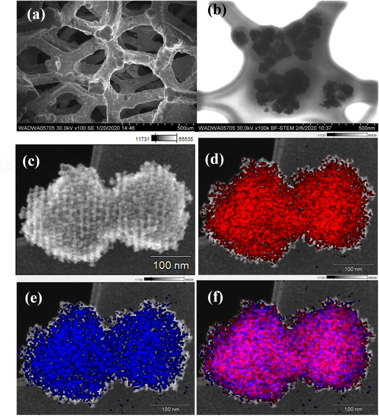
Since the stability of electrode materials is crucial for practical application, we finally examined the durability of om‐Co3O4/NF electrode for HMF oxidation. By conducting successive chronoamperometry runs at 1.457 V (vs. RHE), the om‐Co3O4/NF electrode was used for 17 times of potentiostatic electrolysis cycles. After 17 runs, the FDCA yield [%] for the om‐Co3O4/NF electrode remains above 99.8 % (Figure 5), at FE of 98.2 % with excellent carbon balance. The activity is well retained; for instance, the initial current density at the 17th recycle maintained 90 % of that at the third recycle, and the time required to pass 60 C varies in a non‐systematic manner between about 8 and 16 h over the cycles (Figure S18). Such a good reusability has not been reported before, highlighting the remarkable catalytic stability and excellent selectivity of om‐Co3O4/NF under strongly alkaline conditions for HMF oxidation to FDCA. The SEM images and the elemental mappings of the om‐Co3O4/NF electrode after 17 chronoamperometric runs are displayed in Figure 6. The low‐magnification SEM images of the om‐Co3O4/NF electrode show that the 3D macroporous framework of the pristine NF is still retained, also the rough coating due to the om‐Co3O4 nanoparticles is visible (Figure 6a). Figure 6b,c and the corresponding elemental mapping images of Co and O (Figure 6d–f) show the om‐Co3O4 on lacey film after washing from NF. Those images together with the ones in Figure S19 reveal that cobalt is coated onto the NF, while O is uniformly distributed throughout the whole sample, suggesting that also the NF is surface oxidized. More information is also available in the Supporting Information (Figures S19–S21). These data support the notion derived from the results of the chronoamperometric experiments: om‐Co3O4 based electrolyzer electrodes are stable and can produce hydrogen and the value‐added bio‐product FDCA in the same electrolyzer setup at cathode and anode, respectively.
Figure 5.
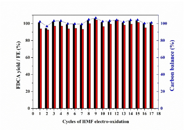
Catalyst recyclability test: the FDCA yields (black column), FE (red column), and carbon balance (blue) for the om‐Co3O4/NF in HMF electro‐oxidation.
Figure 6.
Structural characterization of om‐Co3O4/NF electrode after 17 chronoamperometric runs. (a) Low‐magnification SEM images. (b) Bright‐field STEM image. (c) SEM image. (d–f) Elemental mappings of Co, O, and overlap (scale bar 100 nm).
Conclusion
Om‐Co3O4/NF is shown to be an efficient, selective, stable, and inexpensive electrocatalyst for 5‐hydroxymethylfurfural (HMF) oxidation into 2,5‐furandicarboxylic acid (FDCA), while at the same time allowing hydrogen evolution on the cathode. The 3D structured electrocatalyst surface with higher density of electrocatalytically active sites and reduced charge transfer resistance allows to reach quantitative HMF conversion and >99.8 % yield of FDCA as well as a faradaic efficiency of close to 100 %. Moreover, the integrated two‐electrode system and the remarkably high chemical and structural stability also suggest that the om‐Co3O4/NF electrode is a promising bifunctional electrocatalyst for hydrogen production and biomass conversion in the same electrolyzer. Since there is a number of remaining issues under alkaline conditions, large‐scale production of FDCA is not yet possible via this pathway. However, this study shows a promising alternative to the thermocatalytic route in the synthesis of biomass‐based chemicals using renewable electricity.
Experimental Section
Catalysts synthesis
Synthesis of KIT‐6: Typically, the ordered mesoporous silica, KIT‐6, was synthesized using a procedure described with slight modifications.[ 32 , 33 , 34 , 35 , 36 ] 6 g of copolymer Pluronic P123 was mixed with 217 mL of water under stirring until a homogeneous solution was obtained. 10 mL of concentrated HCl was then added to the solution. After stirring the mixture at 35 °C until complete dissolution of P123, 6 g of n‐butanol was added and stirring was continued. After 1 h of stirring, 13 g of tetraethyl orthosilicate (TEOS) was added into the solution, and the mixture was stirred at 35 °C for 24 h. After that, the mixture was transferred to a polypropylene (PP) container, sealed tightly, and placed in a box oven for hydrothermal treatment at 100 °C for another 24 h. After cooling to room temperature, the precipitate was filtered, dried at 60 °C, and then calcined at 500 °C for 3 h in air.
Synthesis of disordered mesoporous SiO2 : The preparation of disordered mesoporous silica (SiO2) was similar to the procedure used for the preparations of KIT‐6, except that the amount of butanol and TEOS reactants was changed to 12 g and 33.5 g, respectively.
Synthesis of om‐Co3O4 : 1.67 g of Co(NO3)2 ⋅ 6H2O was dissolved in 3 mL of ethanol under sonication. 0.5 g of the KIT‐6 was added to this ethanolic solution and sonicated for 1 h. Subsequently, the obtained mixture was placed in a box oven and dried at 80 °C overnight. Afterwards, the as‐prepared sample was ground to a fine powder and calcined at 350 °C for 5 h to decompose the nitrate and crystallize Co3O4. The om‐Co3O4 was obtained through treating Co3O4/KIT‐6 with 2 m NaOH aqueous solution at 80 °C, followed by washing and drying under vacuum at 50 °C overnight. For comparison, disordered mesoporous Co3O4 (dm‐Co3O4) was prepared using the disordered mesoporous SiO2 as the template and following the procedures stated above. Bulk‐Co3O4 was synthesized by the direct decomposition of Co(NO3)2 ⋅ 6H2O under the same conditions as given for om‐Co3O4.
Electrode preparation
Pre‐treatment of NF: The NF was cut into slices (1 cm×2 cm) and successively ultrasonicated in hydrochloric acid (3 m), acetone, ethanol, and water for 15 min, respectively. Then, the NF was dried in vacuum at 50 °C overnight.
Preparation of the Co3O4/NF electrode: Co3O4 catalyst (4 mg) was dispersed in a 1.0 mL mixed solution containing 900 μL of ethanol and 100 μL of 5 wt % Nafion solution (≈5 % in a mixture of lower aliphatic alcohols and water), followed by sonication for 30 min to obtain a homogeneous catalyst ink. Then, all the catalyst ink was loaded onto the surface of NF and the composite dried at room temperature.
Electrochemical measurements
OER, HER, and electrocatalytic oxidation of HMF were conducted using a Gamry Interface 1010 B electrochemical workstation at room temperature with a three‐electrode system in a H‐type cell, which was separated by a Nafion 117 membrane. Co3O4/NF was directly used as the working electrode (WE), a Pt wire was used as the counter electrode (CE), and a Hg/HgO electrode was used as the reference electrode (RE). The Hg/HgO electrode (RE‐61AP) is available from ALS Co., Ltd, and 1 m sodium hydroxide is used as an electrolyte solution; E 0=118 mV vs. RHE (25 °C). All those reactions were performed in 10 mL of 1.0 m KOH electrolyte solution with and without 10 mm HMF. For catalyst recyclability test, the sample from third recycle was taken after passing a charge of 60 C for HPLC analysis to determine the HMF conversion, FDCA yield, and FE for FDCA. For two‐electrode electrolysis, om‐Co3O4/NF was employed as both anode and cathode. The potential range was cyclically scanned at a scan rate of 5 mV s−1. The potentials were converted to RHE through the Nernst equation: E (RHE)=E (Hg/HgO)+0.059×pH+0.118 V). The scan rate for LSV was kept at 5 mV s−1. The ECSA was evaluated in terms of C dl. The equation for ESCA measurements is: ECSA=C dl/C s, where C s is the specific capacitance, which is assumed to be 0.040 mF cm−2 in 1 m KOH solution, based on values previously reported for metal oxide catalysts. C dl was calculated as half of the slope of the plot of capacitive current in a non‐faradaic double‐layer region against scan rate. CV was performed in 1.0 m KOH with 10 mm HMF at different scan rates of 20, 30, 40, 50, and 60 mV s−1 in a potential window of 0.998–1.098 V vs. RHE. EIS measurements were performed in 1.0 m KOH at 1.517 V vs. RHE from 20000 to 0.01 Hz with an amplitude of 5 mV. Note that in all measurements no iR compensation was applied.
Quantitative product analysis
To analyze the products of HMF oxidation quantitatively and calculate the corresponding FEs, electrolyte solutions during chronoamperometry testing were taken from the cell and analyzed by HPLC on a Shimadzu LC‐2030 chromatograph equipped with a 100 mm organic acid resin column with 8.0 mm inner diameter (i.d.) and a precolumn (40 mm organic acid resin with 8.0 mm i.d.). As the mobile phase, a 2 mm aqueous solution of trifluoroacetic acid was used with a flow rate of 1 mL min−1 at a temperature of 40 °C. For detection, a UV detector was used, and external one‐point calibration was applied to quantify HMF, HMFCA, DFF, FFCA, furoic acid, and FDCA. The HMF conversion [%] and the yields [%] of FDCA were calculated using Equations (1) and 2:
| (1) |
| (2) |
The FE of FDCA was calculated by Equation 3:
| (3) |
where F is the Faraday constant (96485 C mol−1).
Conflict of interest
The authors declare no conflict of interest.
Supporting information
As a service to our authors and readers, this journal provides supporting information supplied by the authors. Such materials are peer reviewed and may be re‐organized for online delivery, but are not copy‐edited or typeset. Technical support issues arising from supporting information (other than missing files) should be addressed to the authors.
Supporting Information
Acknowledgements
The authors thank PD Dr. H. Tüysüz and his team members Dr. G. Moon, Dr. Y. Dai and E. Budiyanto for their kind help and valuable discussions during electrochemical measurements. We also thank Dr. W. Schmidt, and Dr. Z. Cao for helpful discussions, A. Schlüter and N. Pfänder for the electron microscopy analysis, PD Dr. C. Weidenthaler and S. Leiting for XPS analysis, H. Hinrichs and M. Sterling for conducting the HPLC analysis. Financial support from the Deutsche Forschungsgemeinschaft (DFG, German Research Foundation) under Germany's Excellence Strategy‐Cluster of Excellence 2186 ‘The Fuel Science Center’ ‐ ID: 390919832 is gratefully acknowledged. Open Access funding enabled and organized by Projekt DEAL.
C. Wang, H.-J. Bongard, M. Yu, F. Schüth, ChemSusChem 2021, 14, 5199.
References
- 1. Grabowski G., Lewkowski J., Skowronski R., Electrochim. Acta 1991, 36, 1995. [Google Scholar]
- 2. Besson M., Gallezot P., Pinel C., Chem. Rev. 2014, 114, 1827–1870. [DOI] [PubMed] [Google Scholar]
- 3. Huber G. W., Iborra S., Corma A., Chem. Rev. 2006, 106, 4044–4098. [DOI] [PubMed] [Google Scholar]
- 4. Binder J. B., Raines R. T., J. Am. Chem. Soc. 2009, 131, 1979–1985. [DOI] [PubMed] [Google Scholar]
- 5. Motagamwala A. H., Won W., Sener C., Alonso D. M., Maravelias C. T., Dumesic J. A., Sci. Adv. 2018, 4, eaap9722. [DOI] [PMC free article] [PubMed] [Google Scholar]
- 6. Teong S. P., Yi G., Zhang Y., Green Chem. 2014, 16, 2015–2026. [Google Scholar]
- 7. Eerhart A. J. J. E., Faaij A. P. C., Patel M. K., Energy Environ. Sci. 2012, 5, 6407–6422. [Google Scholar]
- 8. van Putten R.-J., van der Waal J. C., de Jong E., Rasrendra C. B., Heeres H. J., de Vries J. G., Chem. Rev. 2013, 113, 1499–1597. [DOI] [PubMed] [Google Scholar]
- 9. Kwon Y., Schouten K. J. P., van der Waal J. C., de Jong E., Koper M. T. M., ACS Catal. 2016, 6, 6704–6717. [Google Scholar]
- 10. Bozell J. J., Petersen G. R., Green Chem. 2010, 12, 539–554. [Google Scholar]
- 11. Zakrzewska M. E., Bogel-Lukasik E., Bogel-Lukasik R., Chem. Rev. 2011, 111, 397–417. [DOI] [PubMed] [Google Scholar]
- 12. Lv G., Wang H., Yang Y., Deng T., Chen C., Zhu Y., Hou X., ACS Catal. 2015, 5, 5636–5646. [Google Scholar]
- 13. Xu C., Paone E., Rodríguez-Padrón D., Luque R., Mauriello F., Chem. Soc. Rev. 2020, 49, 4273–4306. [DOI] [PubMed] [Google Scholar]
- 14. Cha H. G., Choi K. S., Nat. Chem. 2015, 7, 328–333. [DOI] [PubMed] [Google Scholar]
- 15. You B., Liu X., Jiang N., Sun Y., J. Am. Chem. Soc. 2016, 138, 13639–13646. [DOI] [PubMed] [Google Scholar]
- 16. You B., Jiang N., Liu X., Sun Y., Angew. Chem. Int. Ed. 2016, 55, 9913–9917; [DOI] [PubMed] [Google Scholar]; Angew. Chem. 2016, 128, 10067–10071. [Google Scholar]
- 17. Jiang N., You B., Boonstra R., Rodriguez I. M. T., Sun Y., ACS Energy Lett. 2016, 1, 386–390. [Google Scholar]
- 18. Barwe S., Weidner J., Cychy S., Morales D. M., Dieckhofer S., Hiltrop D., Masa J., Muhler M., Schuhmann W., Angew. Chem. Int. Ed. 2018, 57, 11460–11464; [DOI] [PubMed] [Google Scholar]; Angew. Chem. 2018, 130, 11631–11636. [Google Scholar]
- 19. Weidner J., Barwe S., Sliozberg K., Piontek S., Masa J., Apfel U. P., Schuhmann W., Beilstein J. Org. Chem. 2018, 14, 1436–1445. [DOI] [PMC free article] [PubMed] [Google Scholar]
- 20. Zhang N., Zou Y., Tao L., Chen W., Zhou L., Liu Z., Zhou B., Huang G., Lin H., Wang S., Angew. Chem. Int. Ed. 2019, 58, 15895–15903; [DOI] [PubMed] [Google Scholar]; Angew. Chem. 2019, 131, 16042–16050. [Google Scholar]
- 21. Li S. Q., Sun X., Yao Z. H., Zhong X., Cao Y. Y., Liang Y. L., Wei Z. Z., Deng S. W., Zhuang G. L., Li X. N., Wang J. G., Adv. Funct. Mater. 2019, 1904780. [Google Scholar]
- 22. You B., Liu X., Liu X., Sun Y., ACS Catal. 2017, 7, 4564–4570. [Google Scholar]
- 23. Taitt B. J., Nam D.-H., Choi K.-S., ACS Catal. 2019, 9, 660–670. [Google Scholar]
- 24. Nam D.-H. T., Choi B. J., Choi K. Y., ACS Catal. 2018, 8, 1197–1206. [Google Scholar]
- 25. Kang M. J., Park H., Jegal J., Yeon Hwang S., Kang Y. S., Cha H. G., Appl. Catal. B-Environ. 2019, 242, 85–91. [Google Scholar]
- 26. Huang X., Song J., Hua M., Xie Z., Liu S., Wu T., Yang G., Han B., Green Chem. 2020, 22, 843–849. [Google Scholar]
- 27. Liu W.-J., Dang L., Xu Z., Yu H.-Q., Jin S., Huber G. W., ACS Catal. 2018, 8, 5533–5541. [Google Scholar]
- 28. Zhang P. L., Sheng X., Chen X. Y., Fang Z. Y., Jiang J., Wang M., Li F. S., Fan L. Z., Ren Y. S., Zhang B. B., Timmer B. J. J., Ahlquist M. S. G., Sun L. C., Angew. Chem. Int. Ed. 2019, 58, 9155–9159; [DOI] [PMC free article] [PubMed] [Google Scholar]; Angew. Chem. 2019, 131, 9253–9257. [Google Scholar]
- 29. Ren Y., Ma Z., Bruce P. G., Chem. Soc. Rev. 2012, 41, 4909–4927. [DOI] [PubMed] [Google Scholar]
- 30. Walcarius A., Chem. Soc. Rev. 2013, 42, 4098–4140. [DOI] [PubMed] [Google Scholar]
- 31. Gu D., Schüth F., Chem. Soc. Rev. 2014, 43, 313–344. [DOI] [PubMed] [Google Scholar]
- 32. Lu A. H., Schüth F., Adv. Mater. 2006, 18, 1793–1805. [Google Scholar]
- 33. Grewe T., Deng X., Weidenthaler C., Schüth F., Tüysüz H., Chem. Mater. 2013, 25, 4926–4935. [Google Scholar]
- 34. Gu D., Li W., Wang F., Bongard H., Spliethoff B., Schmidt W., Weidenthaler C., Xia Y., Zhao D., Schüth F., Angew. Chem. Int. Ed. 2015, 54, 7060–7064; [DOI] [PubMed] [Google Scholar]; Angew. Chem. 2015, 127, 7166–7170. [Google Scholar]
- 35. Gu D., Jia C.-J., Weidenthaler C., Bongard H.-J., Spliethoff B., Schmidt W., Schüth F., J. Am. Chem. Soc. 2015, 137, 11407–11418. [DOI] [PubMed] [Google Scholar]
- 36. Deng X., Chen K., Tüysüz H., Chem. Mater. 2017, 29, 1, 40–52. [Google Scholar]
- 37. Zhou Y., Dong C.-K., Han L. L., Yang J., Du X.-W., ACS Catal. 2016, 6, 6699–6703. [Google Scholar]
- 38. Bao J., Zhang X., Fan B., Zhang J., Zhou M., Yang W., Hu X., Wang H., Pan B., Xie Y., Angew. Chem. Int. Ed. 2015, 54, 7399–7404; [DOI] [PubMed] [Google Scholar]; Angew. Chem. 2015, 127, 7507–7512. [Google Scholar]
- 39. Yang J., Liu H., Martens W. N., Frost R. L., J. Phys. Chem. C 2010, 114, 111–119. [Google Scholar]
- 40. Sun J., Guo N., Shao Z., Huang K., Li Y., He F., Wang Q., Adv. Energy Mater. 2018, 8, 1800980. [Google Scholar]
- 41. Leng Y., Liu J., Zhang Z., Chen H., Zhang P., Dai S., J. Mater. Chem. A 2019, 7, 27297–27303. [Google Scholar]
- 42. Lou Y., Ma J., Cao X., Wang L., Dai Q., Zhao Z., Cai Y., Zhan W., Guo Y., Hu P., Lu G., Guo Y., ACS Catal. 2014, 4, 4143–4152. [Google Scholar]
- 43. Gonzalez-Prior J., Lopez-Fonseca R., Gutierrez-Ortiz J. I., de Rivas B., Appl. Catal. B 2018, 222, 9–17. [Google Scholar]
- 44. Du Y., Meng Q., Wang J., Yan J., Fan H., Liu Y., Dai H., Microporous Mesoporous Mater. 2012, 162, 199–206. [Google Scholar]
- 45. Gao L., Bao Y., Gan S., Sun Z., Song Z., Han D., Li F., Niu L., ChemSusChem 2018, 11, 2547. [DOI] [PubMed] [Google Scholar]
- 46. Zhang X., Han M., Liu G., Wang G., Zhang Y., Zhang H., Zhao H., Appl. Catal. B 2019, 244, 899. [Google Scholar]
- 47. Wang L., Cao J., Lei C., Dai Q., Yang B., Li Z., Zhang X., Yuan C., Lei L., Hou Y., ACS Appl. Mater. Interfaces 2019, 11, 27743. [DOI] [PubMed] [Google Scholar]
- 48. Gao L., Liu Z., Ma J., Zhong L., Song Z., Xu J., Gan S., Han D., Niu L., Appl. Catal. B 2020, 261, 118235. [Google Scholar]
- 49. Chen H., Wang J., Yao Y., Zhang Z., Yang Z., Li J., Chen K., Lu X., Ouyang P., Fu J., ChemElectroChem 2019, 6, 5797. [Google Scholar]
- 50. Yang G., Jiao Y., Yan H., Xie Y., Wu A., Dong X., Guo D., Tian C., Fu H., Adv. Mater. 2020, 32, 2000455. [DOI] [PubMed] [Google Scholar]
- 51. Zhang M., Liu Y., Liu B., Chen Z., Xu H., Yan K., ACS Catal. 2020, 10, 5179–5189. [Google Scholar]
- 52. McCrory C. C. L., Jung S., Peters J. C., Jaramillo T. F., J. Am. Chem. Soc. 2013, 135, 16977–16987. [DOI] [PubMed] [Google Scholar]
Associated Data
This section collects any data citations, data availability statements, or supplementary materials included in this article.
Supplementary Materials
As a service to our authors and readers, this journal provides supporting information supplied by the authors. Such materials are peer reviewed and may be re‐organized for online delivery, but are not copy‐edited or typeset. Technical support issues arising from supporting information (other than missing files) should be addressed to the authors.
Supporting Information


