

Abstract
Purpose
Respiratory motion is one of the major challenges in radiotherapy. In this work, a comprehensive and clinically plausible set of 4D numerical phantoms, together with their corresponding “ground truths,” have been developed and validated for 4D radiotherapy applications.
Methods
The phantoms are based on CTs providing density information and motion from multi‐breathing‐cycle 4D Magnetic Resonance imagings (MRIs). Deformable image registration (DIR) has been utilized to extract motion fields from 4DMRIs and to establish inter‐subject correspondence by registering binary lung masks between Computer Tomography (CT) and MRI. The established correspondence is then used to warp the CT according to the 4DMRI motion. The resulting synthetic 4DCTs are called 4DCT(MRI)s. Validation of the 4DCT(MRI) workflow was conducted by directly comparing conventional 4DCTs to derived synthetic 4D images using the motion of the 4DCTs themselves (referred to as 4DCT(CT)s). Digitally reconstructed radiographs (DRRs) as well as 4D pencil beam scanned (PBS) proton dose calculations were used for validation.
Results
Based on the CT image appearance of 13 lung cancer patients and deformable motion of five volunteer 4DMRIs, synthetic 4DCT(MRI)s with a total of 871 different breathing cycles have been generated. The 4DCT(MRI)s exhibit an average superior–inferior tumor motion amplitude of 7 ± 5 mm (min: 0.5 mm, max: 22.7 mm). The relative change of the DRR image intensities of the conventional 4DCTs and the corresponding synthetic 4DCT(CT)s inside the body is smaller than 5% for at least 81% of the pixels for all studied cases. Comparison of 4D dose distributions calculated on 4DCTs and the synthetic 4DCT(CT)s using the same motion achieved similar dose distributions with an average 2%/2 mm gamma pass rate of 90.8% (min: 77.8%, max: 97.2%).
Conclusion
We developed a series of numerical 4D lung phantoms based on real imaging and motion data, which give realistic representations of both anatomy and motion scenarios and the accessible “ground truth” deformation vector fields of each 4DCT(MRI). The open‐source code and motion data allow foreseen users to generate further 4D data by themselves. These numeric 4D phantoms can be used for the development of new 4D treatment strategies, 4D dose calculations, DIR algorithm validations, as well as simulations of motion mitigation and different online image guidance techniques for both proton and photon radiation therapy.
Keywords: 4D imaging, 4DMRI, 4D numerical phantom, intrafraction motion, proton therapy
1. INTRODUCTION
Anatomical motions are a challenge for many medical applications. In particular, respiratory motion is a major issue in radiation therapy, as it can negatively and substantially affect the quality of treatment. 1 For imaging such motions, 4DCT is currently considered as the clinical standard. 2 , 3 However, retrospectively reconstructed 4DCTs only represent an average breathing cycle and cannot capture irregular breathing motion. Indeed, irregular breathing during acquisition can lead to substantial artifacts in the resulting 4D data sets. 4 Alternatively, 4DMRI can be acquired over long periods and can help to capture the irregularity of the breathing pattern. 5 This modality, however, does not provide information on tissue density, which is essential for many radiotherapy and other imaging applications. Anatomical motion is also a complex, multivariate problem that is not always reproducible and is often unpredictable, making the ability of 4D imaging techniques to capture the true motion questionable. Much has been reported in the literature on imaging and mitigating motion. However, due to the complexity of the problem, it is often extremely challenging to validate such techniques, as in real patient data, there is no ground truth knowledge of the true, underlying motion that is being imaged or mitigated. For this reason, numerical 4D phantoms have been proposed and widely used in research. The motion of a numerical phantom, even though it might not exactly reflect the motion of real patients, is known exactly and can therefore be considered as the “ground truth” motion of the phantom and used for algorithm validation.
Many such numerical phantoms have been developed. A detailed description of existing phantoms and their applications can be found in comprehensive review articles. 6 , 7 In very early examples, organs are represented analytically as simple geometrical forms like spheres, ellipses, cylinders, or planes. One such example is the Medical Internal Radiation Dose (MIRD) phantom representing an average adult male. 8 Such stylized phantoms can provide a lot of flexibility to model organ motion or variable geometries but are not detailed or realistic enough for assessing complex processes like 4D imaging or treatment planning in radiotherapy. On the other hand, voxelized phantoms based on segmented image data can give more detailed representations of anatomy, but their flexibility is limited in terms of motion and geometric variability. Two examples are the early VIP‐man 9 or the Gesellschaft für Strahlenforschung (GSF) phantom. 10 Later, hybrid phantoms, combining the complexity and realism of voxelized phantoms with the flexibility of stylized phantoms, have also been proposed, for example, the XCAT phantoms 11 , 12 , 13 , 14 and the 4D VIP‐man. 15 These phantoms are based on patient imaging data (CT, MRI), and the surfaces of organs are described by polygonal meshes or with the help of non‐uniform rational B‐splines (NURBS). In the original XCAT phantoms, each organ was modeled as being uniform, apart from some modeled airways in the lung, but some work has also been put into modeling more detailed and realistic structures in the lung and bones. 16 , 17 The XCAT phantoms also further include cardiac and respiratory motion models. 11 Respiratory motion is controlled through a curve describing the diaphragm motion in superior–inferior (SI) direction and one controlling the anterior–posterior (AP) expansion of the chest. 18
As they have developed, numerical motion phantoms have been increasingly used in radiation therapy to assess and validate 4D imaging, online image guidance and motion mitigation techniques. In the context of 4D imaging, phantoms were used for the investigation of image reconstruction algorithms or mitigation of motion artifacts for 4DCT, 19 4D cone‐beam CT (CBCT), 20 , 21 , 22 4D positron emission tomography (PET), 23 , 24 , 25 and single‐photon emission computed tomography (SPECT). 26 Likewise, phantoms have been used to simulate online image guidance scenarios, such as digitally reconstructed radiographs (DRRs), 27 electronic portal imaging, 28 surface motion, cine MRI, or ultrasound guidance. 29 Phantoms also provide the “ground truth” motion and can therefore be used for motion modeling 29 , 30 , 31 as well as for deformable image registration (DIR) performance validation. 32 In photon radiotherapy, phantoms have found applications in treatment planning studies 33 and simulations of gating and tracking. 15 , 34 , 35 , 36
Arguably, however, the most sensitive radiation therapy modality to motion is pencil beam scanned (PBS) proton therapy. 37 Due to the sharp distal fall‐off of the proton depth–dose curve and the sequential (in time) application of individually weighted and narrow proton “pencil beams” (each just a few millimeters in diameter), PBS proton therapy is especially sensitive to patient/tumor geometry changes and the interference with tumor motion. 38 , 39 , 40 As such, bespoke numerical phantoms have been used to study various motion mitigation strategies in proton therapy, such as rescanning, 41 gating, 42 , 43 or tracking 27 or for the development of new 4D dose calculations 44 or 4D planning strategies. 45 As such, the wider availability of flexible and anthropomorphically accurate numerical phantoms, for which “ground truth” motions are known, and which also accurately represent both realistic internal motions and densities, would be of great value to both the radiotherapy and imaging research communities as benchmark data sets for assessing motion imaging and mitigation techniques.
In this paper, we describe a comprehensive set of numerical 4D lung phantoms that have been developed at our institute. For the phantom generation, we expand on an approach already reported by our group, 29 , 44 which mapped motion from 4DMRIs onto static reference CTs using manual landmarks to establish the correspondence between the CT and a reference phase of the 4DMRI. More recently, a similar approach has been reported using multimodality DIR to establish such correlations. 46 In this present work, however, we apply DIR to the segmented lung masks of each subject for high quality inter‐subject geometric correspondence, enabling patient geometries (CTs) to be animated with a large variety of realistic deformable motion patterns (from 4DMRIs) to create an extensive 4D data set for radiotherapy and imaging applications. These patterns also provide the “ground truth” motions for the data set. All developed data sets have been validated using 4D dose calculations for PBS proton therapy which, as described above, we believe is one of the most sensitive radiotherapy modalities to both motion and density variations.
To begin with, we first introduce the image data set preparation procedures and the workflow used to develop the set of 4D numerical phantoms. After the geometrical validation of the phantoms and the evaluation of the densities, an assessment of the accuracy of the motion and modeled density changes within the phantoms is performed using 4D PBS proton therapy dose calculations.
2. MATERIALS AND METHODS
The numerical lung phantoms developed in this work are based on real patient geometries from CTs, combined with motion information from 4DMRIs in order to create synthetic 4DCTs, also called 4DCT(MRI)s. We applied the proposed workflow to 13 different CTs from lung cancer patients, each with pronounced differences in lung shapes/volumes and tumor sizes/locations. Motions have then been extracted from multi‐breathing‐cycle 4DMRIs of five volunteers using DIR. All motion data used for the generation of the phantoms (in the form of moving lung meshes) can be accessed via the following link: https://doi.org/10.5281/zenodo.5016294, while the source code for generating 4DCT(MRI)s can be downloaded from https://doi.org/10.5281/zenodo.5010964.
2.1. Base‐line data sets
2.1.1. Clinical lung cancer CT data
CTs of 13 different lung cancer patients have been used to provide a wide range of realistic anatomical geometries for our phantoms. CT1–CT6 are end exhale (EE) 4DCT phases of six early‐stage non‐small‐cell lung cancer (NSCLC) patients, whereas CT7–CT13 were acquired using visually guided voluntary deep‐inspiration breath‐hold (DIBH) for seven advanced‐stage NSCLC patients. 47 , 48 All CTs were acquired on Siemens CTs (Siemens Healthineers, Erlangen, Germany) with a resolution of 0.98 × 0.98 × 2 mm3. The 13 CTs thus exhibit large variabilities in tumor size, tumor location, lung shape, and volume. For all CTs, both lungs were segmented manually by physicists. The 3D rendering of the lungs and corresponding volumes are shown in Figure 1.
FIGURE 1.

(a) Top: CT geometries from 13 patients. CT1–CT6 are end exhale (EE) reference CTs extracted from 4DCTs, whereas CT7–CT13 were acquired during deep‐inspiration breath‐hold (DIBH). Bottom: MRI lung geometries from five volunteers at EE reference phases from the 4DMRIs. (b) Volumes of both lung halves for CTs and MRIs. For the 4DMRIs the volumes for both the EE and the end inhalation (EI) reference state are shown
2.1.2. Volunteer lung 4DMRI data
The time‐resolved deformable respiratory motion was derived from time‐resolved 3D volumetric MRI data (4DMRIs) of five volunteers acquired on a 1.5 T MRI scanner (MAGNETOM Aera, Siemens Healthineers). The volumetric MRI had a 500 × 275 × 400 mm3 field of view with a 3.125 × 3.125 × 3.125 mm3 image resolution. For imaging, a motion‐aware acquisition technique was used which is based on a spoiled gradient echo sequence which acquires core and pseudo‐randomly sampled peripheral k‐space patches alternately. The motion‐aware reconstruction “corrects” the spatial offset between a peripheral patch and a reference EE core utilizing DIR. This yields an effective time resolution of 2.25 Hz. 49 MRI data were acquired over 11 min. The 4DMRI data sets used in the present study were acquired and processed as part of our previous work, 29 to which the interested reader is referred to for further details and analysis. Both lungs were manually segmented on the reference EE and the following end inhalation (EI) phase of the reconstructed 4DMRI (EE lung shapes visualized at the bottom of Figure 1). For the generation of the example 4D phantoms, five breathing cycles following the reference EE phase for each 4DMRI were considered. In addition, a longer pattern of 20 cycles was extracted for MRI4, as an example representing breathing irregularities over a longer time‐scale. More cycles from MRI1, MRI2, and MRI5 exhibiting large motion irregularities were also selected. In total, eight deformable motion patterns consisting of 67 breathing cycles were selected.
2.2. 4DCT(MRI) workflow
The originating CT data sets consist either of EE reference phases from 4DCTs or static DIBH CTs. To correctly map the motion from the 4DMRI onto the reference CT, a similar 4DMRI reference state first needs to be defined. For the EE CTs, the EE states used for the 4DMRI reconstruction and DIR were selected. For DIBH CTs, the next EI state after this 4DMRI EE state was used. A schematic of the complete workflow is illustrated in Figure 2. First, both lungs were manually segmented on both the reference CT and the reference MRI. From the segmented MRI lungs, surface meshes were extracted using the visualization toolkit (vtk).a , 50 Second, these binary CT lung masks were then registered to the MRI lung masks using Plastimatch,b to establish anatomical correlation between the CT and MRI lung shapes. These registrations of the binary masks were performed separately for both lung halves. For all binary mask registrations, we first utilized a 3D affine registration, followed by a 3D multi‐resolution B‐spline registration using the mean‐squared error metric. The results of the lung DIR were used to deform the MRI surface meshes to match the CT lungs, such that mesh point correlation between the CT and MRI lungs is established. If the registration and deformation of the surface mesh led to unsatisfactory results (e.g., part of lung missing), strategically placed landmarks can be manually defined and used to guide another registration. These landmarks can be placed in areas where the previous registration had difficulties by selecting landmarks in similar anatomical locations on the lung surface of the CT and MRI. Moreover, grid points within the CT and MRI lungs were also inserted. For that purpose, a regular grid of points with a spacing of 15 mm was first inserted inside the CT surface mesh, which was then interpolated to positions inside the MRI mesh. Third, the Deformable Vector Fields (DVFs) resulting from registering each 4DMRI state to the reference MRI state were used to warp the reference CT mesh (including internal grid points) for generating time‐resolved CT meshes. Next, for each state the position of every CT mesh or grid point P s was subtracted from the corresponding point position Pref in the reference mesh, and the resulting vectors (Pref – P s starting at P s ) were interpolated from the sparse deformation information to a continuous DVF for the CT using a B‐spline 51 insight toolkit (itk)c implementation. 52 In the same step, the DVF is also extrapolated into the abdominal region, such that the motion at the inferior border of the CT is zero unless the moving lungs would extend outside of the CT field of view, in which case the full extent of the lung motion is allowed. To preserve sliding organ motions along boundaries, the motion of the ribcage and body was set to zero by applying a mask to anatomical regions assumed to be static. On the reference CT, this was manually contoured to separate the static ribcage from the moving parts inside the thoracic and abdominal cavity. Finally, the synthetic 4DCT(MRI) data were derived by warping the reference CT with the resulting continuous DVFs.
FIGURE 2.

Workflow to generate a 4DCT(MRI) based on a reference CT and a 4DMRI
It is important to note that these resulting DVFs provide the “ground truth” motion of each synthetically generated 4DCT(MRI) data set. Throughout the rest of this paper, we will use the following notation to refer to such data sets: for example CT1(MRI1) refers to the 4DCT(MRI) generated using the CT1 reference geometry and motion from MRI1.
2.3. Phantom validation
2.3.1. Geometrical validation
The quality of the DIR of the binary lung masks can be assessed by checking the registration results visually and quantitatively by calculating the dice coefficient. CT surface meshes were also directly generated from the segmented CT lung masks using vtk 50 and used to visually check the similarity to the deformed CT lung meshes. The mesh point correspondence between the deformed CT meshes and the MRI meshes was visually checked in ParaViewd to make sure corresponding points are in a similar anatomical location. Further, the deformed mesh was converted into a binary mask and the dice coefficient of this deformed mask and the originally segmented CT mask for all registrations was calculated.
2.3.2. Density validation
For all further validations, we focused on the six 4DCTs (CT1–CT6), as they provide both density and motion information which are necessary for validation. To validate our workflow, we generated what we call a 4DCT(CT) for each of the 4DCTs by warping the reference EE phases according to the 4DCT motion itself, following the exact procedures in Figure 2. However, as the motion and the reference image came from the same subject, no DIR of binary lung masks is required. Moreover, each 4DCT phase was registered to the reference phase using a 3D multi‐resolution B‐spline registration in Plastimatch.
Based on the current procedures, density changes within the lung region are not considered in the generation of a 4DCT(MRI) or 4DCT(CT), as the positions of voxels are only warped, without changing their Hounsfield values in either the image registration or warping process. However, in reality, respiratory motion leads to a change of lung volume, whereas the mass of the lung stays approximately the same, leading to a change of the lung density. 53 Therefore, the effect of density changes was evaluated by calculating the mean Hounsfield units (HU) in the lung (including tumor) for each phase of both the original 4DCT and the 4DCT(CT).
Additionally, we have calculated a DRR simulating AP fluoroscopic imaging for each of the six 4DCTs and the corresponding 4DCT(CT)s. 54 Such a DRR was generated for the EI state of each 4DCT, as the biggest differences between the 4DCT and 4DCT(CT) are expected for this state due to the choice of the EE reference phase for the 4DCT(CT). The DRRs of the 4DCT and the derived 4DCT(CT) were then compared visually and in terms of relative gray level differences.
2.3.3. Motion and density validation
Another limitation of the current numerical phantoms is that the rib motion is not modeled. This is a consequence of masking out the body and ribs during the DIR process (to ensure smooth sliding boundaries between the lung and ribs/chest wall). To separate the effect of the ribcage motion and the density changes, we introduced another synthetic 4D image for validation, a “patched 4DCT” (p4DCT). This is obtained by combining the static ribcage of the reference phase with the changing interior regions (lungs, heart, etc.) of the original 4DCT. The static mask of the EE 4DCT reference phase, which is used for the 4DCT(CT) generation, can be applied for this purpose. For voxels in the non‐moving part the EE HU value is kept for all phases, whereas for voxels within the moving part the HU value of that voxel from the respective 4DCT phase is utilized. Therefore, the p4DCT has the same HUs within the lung as the originating 4DCT reflecting breathing‐induced density changes, but still has a static ribcage as in the 4DCT(CT).
To investigate the magnitude of the impact of these two limitations, both effects were studied using 4D dose calculations for PBS proton therapy treatment plans. Four‐dimensional dose distributions 44 , 55 were calculated for 3D (static), two‐field single‐field uniform dose (SFUD) plans, optimized on the planning target volume (PTV) (clinical target volume (CTV) extended by a 2 mm isotropic margin) of the reference phase of the 4DCT. The beam model and delivery dynamics of the PSI gantry 2 56 were used and 4D dose calculations performed using the deforming dose grid approach, 44 which considers the different motion scenarios, as well as induced density changes from 4DCT, 4DCT(CT) and the p4DCT, respectively. For example, by comparing 4D dose distributions calculated on the 4DCT to 4D dose distributions on the p4DCT, the effect of the ribcage motion can be assessed. On the other hand, a comparison of 4D dose distributions for the p4DCT and the 4DCT(CT) indicates the effect of the density changes.
We have created static plans on the EE reference phases of CT1–CT6 with two fields. A field from the side (left–right or right–left) and a second field with a 45° angle from the front were chosen for all plans. The 4D dose distributions calculated on the 4DCT, p4DCT and the 4DCT(CT) were compared in terms of dose differences and a 3D gamma analysis using a 2% dose difference (absolute) and a distance to agreement of 2 mm (2%/2 mm). A dose threshold of 10% of the prescribed dose (2 GyRBE per fraction) was applied to define the analysis region. V 95% of the CTV and the mean dose to the healthy lung half surrounding the tumor was examined.
3. RESULTS
3.1. The 4DCT(MRI) numerical phantom library
The 4DCT(MRI) phantoms are based on 13 CTs and eight deformable motion patterns from five 4DMRIs. An illustration of the motion patterns is displayed in Figure 3 for one example point in the dome of each lung half (see Figure 3a). Figure 3b,c illustrates the SI amplitudes and the periods of the 4DMRI motion patterns. A total of 67 individual breathing cycles from five 4DMRIs are included, thus leading to a data set of 871 different 4DCT(MRI) breathing cycles. The animation of the CT anatomies with different motion patterns results in an average tumor center SI motion amplitude of 7 ± 5 mm. For all 4DCT(MRIS)s, averaged over the breathing cycles of each motion pattern, the minimum observed tumor amplitude is 0.5 mm and tumor displacements up to 22.7 mm were observed.
FIGURE 3.

For each of the 4DMRI geometries, a point in the dome of each half of the lung was selected (see (a) for MRI1) and the superior–inferior (SI) motion is analyzed (left: red, right: green). Boxplots of amplitudes (SI) (b) and periods (c) over all breathing cycles of the 4DMRIs. SI displacements over time for MRI1–MRI5 (d–h). Selected motion patterns for 4DCT(MRI) generation are marked by gray shaded areas
Figure 4 shows example 4DCT(MRI) slices from CT2(MRI1) and CT11(MRI2). In Figure 4a–d, the EE reference phase of CT2, as well as an EI phase of CT2(MRI1), are presented. Figure 4e–h depicts the DIBH reference CT11 together with an EE slice of CT11(MRI2). Animations of one example cycle of the 4DCT(MRI)s, CT2(MRI1), and CT11(MRI2) can be found in Figure S1. Figure S2 also shows the CT2 geometry animated by a breathing cycle from the other MRIs. The variability of the CT data set is illustrated in Figure S3, where each CT is animated with the same breathing cycle following the reference phase of MRI1.
FIGURE 4.

Example coronal and sagittal 4DCT(MRI) slices at different breathing phases of CT2(MRI1) (a–d) and CT11(MRI2) (e–h). For CT2(MR1) the reference end exhale (EE) phase and an end inhalation (EI) phase are shown. For CT11(MRI2) the deep‐inspiration breath‐hold (DIBH) reference and an EE phase are displayed. The clinical target volume (CTV) is contoured on each image. The white lines have been inserted for visual reference
3.2. Phantom validation
3.2.1. Geometrical validation
The results of the registration of the binary masks and the subsequent deforming of the MRI lung meshes were checked visually by comparing the original CT lung mesh and the deformed MRI lung mesh. Additionally, correspondence was also visually checked for some mesh points. The dice coefficient was calculated between the originally segmented lung and the deformed lung. We obtained a mean dice coefficient of 0.963 ± 0.010 and the minimal dice coefficient is 0.931 over all investigated cases.
3.2.2. Density validation
The mean HU values inside the lung for each breathing phase were calculated for all 4DCTs and 4DCT(CT)s. Whereas the mean HU inside the lung remains almost constant over the whole breathing cycle for all 4DCT(CT)s, a decrease of the mean lung HU between full exhalation and full inhalation can be observed for the original 4DCTs. The density changes between opposite extreme breathing phases lead to HU changes up to 49 HU for the examined 4DCTs. An average mean lung density decrease from the reference EE phase to full inhalation of 37 ± 10 HU could be observed for the six 4DCTs and 6 ± 3 HU for the six 4DCT(CT)s. This resulted in mean lung density differences of 40 ± 10 HU between the 4DCT and the 4DCT(CT) in full inhalation, with differences up to 55 HU being observed.
An overlay of a DRR generated for the EI state of the 4DCT and 4DCT(CT) for CT1–CT6 is shown on the left in Figure 5a–f. The appearance of both DRRs is very similar for all studied patient geometries. Some differences are visible at the boundary of the ribcage, especially for CT4 (Figure 5d) and CT6 (Figure 5f) due to the moving ribcage in the 4DCT, as well as some differences in the rib positions. The relative change of the DRR image intensities from the 4DCT(CT) relative to the values from the DRR from the 4DCT is depicted on the right in Figure 5a–f. Again, some differences are visible due to the moving ribcage and body surface of the 4DCT. As previously explained, the 4DCT(CT) tends to overestimate the lung density for other states than the EE reference state. This is also represented in the relative DRR differences by the blue shading of the lung area. The relative change inside the body, however, is below 5% for >81% of the pixels for all six cases.
FIGURE 5.
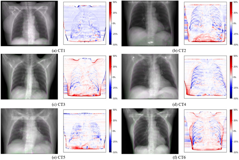
Overlay of end inhalation digitally reconstructed radiograph (DRR) from 4DCT (green) and 4DCT(CT) (pink) for CT1–CT6 (left) and relative change of the pixel values of the 4DCT(CT) DRR relative to the 4DCT DRR (right)
3.2.3. Motion and density validation
We compared the original 4DCT to the synthetic 4DCT(CT) and the p4DCT for CT1–CT6. The top row of Figure 6 shows an EI slice of the 4DCT (green) overlaid with the 4DCT(CT) (pink) for all six cases. Due to the static ribcage of the 4DCT(CT), differences are visible in the body surface, ribs, and the anterior edges of the lung. However, for all studied cases, the AP lung expansion is very small and only around 3 mm for CT6, which shows the largest ribcage motion. Due to the DIR uncertainty and interpolation, there are also some differences inside the lung. However, the differences in the anatomy with considerable respiratory changes, such as the diaphragm, are only marginal. For the abdominal organs, the DVF obtained by extrapolation of the DVF of the lungs can lead to some differences (see, e.g. air in Figure 6b). The bottom of Figure 6 shows an overlay of the 4DCT (green) and the p4DCT (pink). The same differences are visible in the ribs, body surface, and at the anterior edge of the lung again due to the static ribcage of the p4DCT. There are no differences in the lung and abdominal organs. An animation of the original 4DCT, 4DCT(CT), and p4DCT of CT2 is given in Figure S4.
FIGURE 6.

Overlay of sagittal slice of 4DCT (green) and 4DCT(CT) (pink) in (a–f) and patched 4DCT (pink) in (g–l) for CT1–CT6. All slices show the end inhalation phase and the tumor is visible in all slices
The static dose distribution and the 4D dose distributions calculated on the 4DCT, 4DCT(CT), and p4DCT are shown for the example CT6 in Figure 7a–d. Figure 7e shows the 4D dose differences of the original 4DCT and the 4DCT(CT) for CT6. The dose difference of the p4DCT and the 4DCT(CT) in Figure 7f shows the impact of the density differences in the lung and the DVF interpolation. There is more dose distal to the tumor for the p4DCT due to the higher density in the lung in the 4DCT(CT). On the other hand, Figure 7g shows the impact of the ribcage motion in the dose difference of the original 4DCT and the p4DCT. The results of a 2%/2 mm gamma analysis between the six 4DCTs, the p4DCTs, and the 4DCT(CT)s are listed in Table 1. The gamma pass rates between the 4DCT and 4DCT(CT) are only slightly smaller than the gamma pass rates between the 4DCT and p4DCT. CT3, with the largest tumor isocenter motion (2.8 cm in SI direction), shows larger differences between the three different 4DCT data sets. Another explanation for this, are the larger tumor deformations, which can be seen in Figure 6. V 95% in the CTV and the mean dose in the lung half with the tumor are also listed in Table 1. A clear degradation of the dose coverage in terms of V 95% is visible due to the breathing motion when compared to the static plan, but the dose coverage and the mean lung dose for the 4D plans are very similar among the three 4DCT scenarios, showing that comparable dosimetric indices can be achieved using the 4DCT(CT).
FIGURE 7.

Dose distributions and dose differences for CT6 from 4D dose calculation on the original 4DCT (b), 4DCT(CT) (c), and patched 4DCT (d). The static dose distribution is shown in (a) and the chosen field directions are indicated with white arrows. Dose distributions and differences are shown as percentages of the prescribed dose and the same colormaps were used for all dose distributions and dose differences, respectively
TABLE 1.
For each of 4DCTs the 2%/2 mm gamma pass rates between the 4DCT and the patched 4DCT (p4DCT), the 4DCT, and the 4DCT(CT) as well as the p4DCT and the 4DCT(CT) are listed
| Gamma pass rate (%) | V 95% CTV (%) | Mean dose healthy lung (%) | |||||||||
|---|---|---|---|---|---|---|---|---|---|---|---|
| 4DCT/p4DCT | 4DCT/4DCT(CT) | p4DCT/4DCT(CT) | Static | 4DCT | p4DCT | 4DCT(CT) | Static | 4DCT | p4DCT | 4DCT(CT) | |
| CT1 | 95.0 | 93.8 | 98.6 | 82.8 | 34.2 | 33.7 | 33.5 | 3.6 | 3.4 | 3.5 | 3.4 |
| CT2 | 92.9 | 90.8 | 97.9 | 97.5 | 39.0 | 38.3 | 40.1 | 5.3 | 5.7 | 5.7 | 5.6 |
| CT3 | 82.5 | 77.3 | 94.9 | 89.9 | 26.3 | 27.0 | 32.3 | 3.8 | 4.2 | 4.2 | 4.0 |
| CT4 | 97.8 | 97.2 | 99.2 | 91.9 | 36.6 | 37.2 | 46.4 | 1.9 | 1.9 | 1.9 | 1.9 |
| CT5 | 92.6 | 88.7 | 96.8 | 93.5 | 66.3 | 67.0 | 67.8 | 3.3 | 3.5 | 3.5 | 3.1 |
| CT6 | 98.9 | 96.8 | 97.9 | 92.6 | 66.2 | 66.5 | 64.7 | 12.0 | 12.0 | 12.0 | 11.6 |
| Average | 93.3 | 90.8 | 97.5 | 91.4 | 44.7 | 44.9 | 47.5 | 5.0 | 5.1 | 5.1 | 4.9 |
Note: V 95% and the mean dose to the surrounding healthy lung half were calculated for the static plan and the 4D dose calculations for the 4DCT, p4DCT, and 4DCT(CT).
Abbreviation: CTV, clinical target volume.
4. DISCUSSION
As shown in this paper, our numerical 4D phantoms are based on a large variety of realistic patient geometries (CTs) and a large motion library based on volunteer 4DMRIs, thus covering a wide variety of 4D treatment scenarios. The phantoms provide an important foundation for further progress in 4D treatment planning and optimization, for the comparison of different motion mitigation techniques under different scenarios as well as for the simulation and comparison of time‐resolved image guidance methods for both proton and photon radiation therapies. The DVFs have been used directly to warp the reference CTs and thus they represent the true underlying motion of each 4DCT(MRI). Due to the availability of these “ground truth” DVFs, the phantoms can also be used for the development or comparison of different DIR algorithms. The use of motion from a 4DMRI instead of a 4DCT allows studying irregular breathing patterns. As 4DMRI leads to no additional dose, long acquisitions are possible, which can for example show the drift of the abdominal organs while the patient lies on the treatment couch. 5 The selected breathing cycles allow for the study of varying degrees of motion irregularity, which is usually not possible with clinically used single‐cycle 4DCTs. Based on this 4D phantom development, we plan several follow‐up studies investigating the impact of motion irregularity on proton treatments. We have also included some proton dose distributions under irregular motion scenarios in Figure S5. To allow others to animate their CTs with different motion patterns, we have made the code for the 4DCT(MRI) generation, together with the complete 4DMRI motion library openly available.
In the original approach developed at our institute for the liver, correspondence between cases was established by generating a mesh from manual landmarks in predefined anatomical locations, leading to a lot of manual work. 44 The approach presented in this paper for lung uses DIR of binary masks to establish correspondence and thus gets rid of this labor intensive step. The workflow could further be automated by automatic segmentation of the lung. A fast, mostly automatic workflow is highly advantageous for adding further CTs and motion patterns to further improve the variability of the phantoms. Additionally, the approach presented here could also more easily be extended to further organs, like the liver, heart or pancreas, whereas motion modeling could be used to further expand the motion library. 29 , 30 , 31 , 54
In the literature, a DIR‐based approach to map respiratory motion from 4DMRI onto CTs for abdominal tumors treated with carbon ion therapy has been presented, 46 in which each respiratory phase of the single‐breathing‐cycle 4DMRI is registered to a reference phase of the single‐cycle 4DMRI. They then used multimodality DIR to register a CT and the reference state of the 4DMRI acquired for the same patient to establish correspondence. This approach also assumes a rigid ribcage. Our approach, as described in this paper, together with our previous approach for liver 44 allows the use of a CT and 4DMRI of a different patient or volunteer to be used, which makes it possible to animate one CT with different breathing patterns and consequently create a more extensive data set. Also, our experience shows that the multimodality registration of a CT and an MRI of a different subject is rather challenging due to the different anatomical features. We have therefore applied DIR both to extract the motion from the 4DMRI and to register the binary lung masks to establish correspondence. It is, however, well known that different DIR algorithms can lead to considerably different deformation fields for both intra‐ and interfraction changes imaged for the same patient. 32 , 48 In addition, the registration of different breathing phases from a 4DMRI or a 4DCT is challenged by the presence of sliding organ boundary motion which can lead to discontinuous DVFs. Smooth registration algorithms (like B‐spline) can thus lead to incorrect displacement fields near the boundaries of sliding organs. We use static masks leading to a static ribcage in our phantoms to overcome these potential errors. Further, the registration approach used for the 4DMRIs used a sliding organ mask to deal with this issue. 49 There are also several dedicated registration approaches dealing with sliding boundary motion. 57 , 58
A limitation of the phantoms are the density changes in the lung occurring during breathing, which are not considered in the DIR and image warping of the reference CT. Using an EE CT leads to an overestimation of the lung density in the other phases of the synthetic CT. In contrast, the lung density is underestimated for a DIBH CT. The density fluctuations in the lung could be considered by scaling the overall lung density according to observed patient data 33 or by scaling the individual voxel intensities according to the expected density fluctuations calculated from the Jacobian determinant of the DVF. 53 , 59 , 60 , 61 It will be considered in an upgrade of this phantom.
Another limitation is the static ribcage of our phantom. Even for patients breathing shallowly or wearing an abdominal mask restricting the breathing motion, the ribcage is never completely static, and there is also a substantial number of patients undergoing radiotherapy that have non‐shallow breathing patterns. However, for the studied cases using 4DCT motion, we saw a larger impact due to the density differences in the lung than just due to the static ribcage. Additionally, although the provided phantoms may not reflect the full truth, they still provide a number of clinically plausible and realistic scenarios, which is the goal of every numerical phantom. We plan to include both a way to consider the density fluctuations as well as a moving ribcage in the future. As, however, the 4DMRI data used in this project were reconstructed with a method assuming a static ribcage, 49 these data are not suitable for extracting ribcage motion and such motion would have to be gained from 4DCTs or another 4DMRI approach. 5
We also have to remark on the fact that the motion used for the phantoms was extracted from 4DMRIs of healthy volunteers. While the breathing motion of a lung cancer patient could show different characteristics and especially the motion of cancerous lung tissue could differ from healthy lung tissue leading to differences in tumor motion and deformation, the workflow described in this paper could just as easily be used for 4DMRI acquired for patients for which a CT/4DCT was also acquired. Additionally, subject‐specific 4DCT(MRI)s could also be created using a “motion of the day,” extracted either from a daily 4DMRI or reconstructed from surrogate data, such as from ultrasound. 29
Whereas in the original XCAT phantom, each organ was modeled as being homogeneous, a lot of effort has been put into a realistic representation of the heterogeneities in the lung by modeling the structures in the lung. 16 , 17 On the other hand, our 4D numerical lung phantoms are completely based on real patient image data and thus directly provide a realistic representation of tissue heterogeneity, which is essential for accurate dose calculation and realistic image guidance simulation, especially for proton therapy.
5. CONCLUSION
We have developed and validated a method for the generation of 4DCT(MRI) numerical lung phantoms, which provide a realistic representation of a large selection of anatomical and motion scenarios, as well as the accessible deformation vector fields of each 4DCT(MRI). The flexible workflow allows including additional image data and extension of the phantoms to further organs, such as the liver or pancreas. Such phantoms have a very wide range of applications for the investigation of motion mitigation techniques for proton therapy as well as the simulation and comparison of different image guidance techniques.
CONFLICT OF INTEREST
The authors have no conflicts to disclose.
Supporting information
Supporting Information
ACKNOWLEDGMENTS
This project is funded by the Swiss Cancer Research Foundation (KFS‐4517‐08‐2018) and the Swiss National Science Foundation, SNSF (project number 320030 163330/1). Open access funding provided by ETH‐Bereich Forschungsanstalten. WOA Institution: ETH‐Bereich Forschungsanstalten.
Duetschler A, Bauman G, Bieri O, et al. Synthetic 4DCT(MRI) lung phantom generation for 4D radiotherapy and image guidance investigations. Med Phys. 2022;49:2890‐2903. 10.1002/mp.15591
Current Address: Varian Medical Systems Imaging Laboratory GmbH, Daettwil, Switzerland. Miriam Krieger, Varian Medical Systems Particle Therapy GmbH, Troisdorf, Germany
Footnotes
http://vtk.org. Accessed June 2, 2021.
www.plastimatch.org. Accessed June 2, 2021.
www.itk.org. Accessed June 2, 2021.
www.paraview.org. Accessed June 2, 2021.
DATA AVAILABILITY STATEMENT
The 4DMRI lung mesh data used in this study is openly available on Zenodo at https://doi.org/10.5281/zenodo.5016294, reference number 10.5281/zenodo.5016294. The code for generating 4DCT(MRI)s is openly available on Zenodo at https://doi.org/10.5281/zenodo.5010964, reference number 10.5281/zenodo.5010964. The CT and 4DCT(MRI) data are not publicly available due to privacy or ethical restrictions, but some of them are available on request from the corresponding author.
REFERENCES
- 1. Korreman SS. Motion in radiotherapy: photon therapy. Phys Med Biol. 2012;57(23):R161. 10.1088/0031-9155/57/23/R161 [DOI] [PubMed] [Google Scholar]
- 2. Keall P. 4‐Dimensional computed tomography imaging and treatment planning. Semin Radiat Oncol. 2004;14(1):81‐90. 10.1053/j.semradonc.2003.10.006. [DOI] [PubMed] [Google Scholar]
- 3. Kwong Y, Mel AO, Wheeler G, Troupis JM. Four‐dimensional computed tomography (4DCT): a review of the current status and applications. J Med Imaging Radiat Oncol. 2015;59(5):545‐554. 10.1111/1754-9485.12326. [DOI] [PubMed] [Google Scholar]
- 4. Keall PJ, Mageras GS, Balter JM, et al. The management of respiratory motion in radiation oncology report of AAPM Task Group 76. Med Phys. 2006;33(10):3874‐3900. 10.1118/1.2349696. [DOI] [PubMed] [Google Scholar]
- 5. von Siebenthal M, Székely G, Gamper U, Boesiger P, Lomax A, Cattin P. 4D MR imaging of respiratory organ motion and its variability. Phys Med Biol. 2007;52(6):1547‐1564. 10.1088/0031-9155/52/6/001. [DOI] [PubMed] [Google Scholar]
- 6. Xu XG, Eckerman KF. Handbook of Anatomical Models for Radiation Dosimetry. CRC Press; 2010. [Google Scholar]
- 7. Kainz W, Neufeld E, Bolch WE, et al. Advances in computational human phantoms and their applications in biomedical engineering—a topical review. IEEE Trans Radiat Plasma Med Sci. 2018;3(1):1‐23. 10.1109/trpms.2018.2883437. [DOI] [PMC free article] [PubMed] [Google Scholar]
- 8. Snyder WS, Ford MR, Warner GG. Estimates of absorbed fractions for monoenergetic photon sources uniformly distributed in various organs of a heterogeneous phantom. J Nucl Med. 1969;(suppl 3):7‐52. [PubMed] [Google Scholar]
- 9. Xu XG, Chao TC, Bozkurt A. VIP‐Man: an image‐based whole‐body adult male model constructed from color photographs of the visible human project for multi‐particle Monte Carlo calculations. Health Phys. 2000;78(5):476‐486. 10.1097/00004032-200005000-00003. [DOI] [PubMed] [Google Scholar]
- 10. Petoussi‐Henss N, Zankl M, Fill U, Regulla D. The GSF family of voxel phantoms. Phys Med Biol. 2002;47(1):89‐106. 10.1088/0031-9155/47/1/307. [DOI] [PubMed] [Google Scholar]
- 11. Segars WP, Sturgeon G, Mendonca S, Grimes J, Tsui BMW. 4D XCAT phantom for multimodality imaging research. Med Phys. 2010;37(9):4902‐4915. 10.1118/1.3480985. [DOI] [PMC free article] [PubMed] [Google Scholar]
- 12. Segars WP, Bond J, Frush J, et al. Population of anatomically variable 4D XCAT adult phantoms for imaging research and optimization. Med Phys. 2013;40(4):043701. 10.1118/1.4794178. [DOI] [PMC free article] [PubMed] [Google Scholar]
- 13. Norris H, Zhang Y, Bond J, et al. A set of 4D pediatric XCAT reference phantoms for multimodality research. Med Phys. 2014;41(3):033701. 10.1118/1.4864238. [DOI] [PMC free article] [PubMed] [Google Scholar]
- 14. Segars WP, Norris H, Sturgeon GM, et al. The development of a population of 4D pediatric XCAT phantoms for imaging research and optimization. Med Phys. 2015;42(8):4719‐4726. 10.1118/1.4926847. [DOI] [PMC free article] [PubMed] [Google Scholar]
- 15. Zhang J, Xu XG, Shi C, Fuss M. Development of a geometry‐based respiratory‐motion‐simulating patient model for radiation treatment dosimetry. J Appl Clin Med Phys. 2008;9(1):16‐28. 10.1120/jacmp.v9i1.2700. [DOI] [PMC free article] [PubMed] [Google Scholar]
- 16. Abadi E, Segars WP, Sturgeon GM, Roos JE, Ravin CE, Samei E. Modeling lung architecture in the XCAT series of phantoms: physiologically based airways, arteries and veins. IEEE Trans Med Imaging. 2018;37(3):693‐702. 10.1109/TMI.2017.2769640. [DOI] [PMC free article] [PubMed] [Google Scholar]
- 17. Abadi E, Segars WP, Sturgeon GM, Harrawood B, Kapadia A, Samei E. Modeling “textured” bones in virtual human phantoms. IEEE Trans Radiat Plasma Med Sci. 2019;3(1):47‐53. 10.1109/trpms.2018.2828083. [DOI] [PMC free article] [PubMed] [Google Scholar]
- 18. Panta RK, Segars P, Yin FF, Cai J. Establishing a framework to implement 4D XCAT Phantom for 4D radiotherapy research. J Cancer Res Ther. 2012;8(4):565‐570. 10.4103/0973-1482.106539. [DOI] [PMC free article] [PubMed] [Google Scholar]
- 19. Bernatowicz K, Keall P, Mishra P, Knopf A, Lomax A, Kipritidis J. Quantifying the impact of respiratory‐gated 4D CT acquisition on thoracic image quality: a digital phantom study. Med Phys. 2014;42(1):324‐334. 10.1118/1.4903936. [DOI] [PubMed] [Google Scholar]
- 20. Zhang Q, Hu YC, Liu F, Goodman K, Rosenzweig KE, Mageras GS. Correction of motion artifacts in cone‐beam CT using a patient‐specific respiratory motion model. Med Phys. 2010;37(6):2901‐2909. 10.1118/1.3397460. [DOI] [PMC free article] [PubMed] [Google Scholar]
- 21. Zhang L, Zhang Y, Zhang Y, et al. Markerless four‐dimensional‐cone beam computed tomography projection‐phase sorting using prior knowledge and patient motion modeling: a feasibility study. Clin Transl Med. 2017;3(6):185‐193. Accessed October 2, 2020. http://www.ncbi.nlm.nih.gov/pubmed/30135868 [PMC free article] [PubMed] [Google Scholar]
- 22. Zhi S, Kachelrieß M, Mou X. High‐quality initial image‐guided 4D CBCT reconstruction. Med Phys. 2020;47(5):2099‐2115. 10.1002/mp.14060. [DOI] [PubMed] [Google Scholar]
- 23. Lamare F, Cresson T, Savean J, Cheze Le Rest C, Reader AJ, Visvikis D. Respiratory motion correction for PET oncology applications using affine transformation of list mode data. Phys Med Biol. 2007;52(1):121‐140. 10.1088/0031-9155/52/1/009. [DOI] [PubMed] [Google Scholar]
- 24. Reyes M, Malandain G, Koulibaly PM, González‐Ballester MA, Darcourt J. Model‐based respiratory motion compensation for emission tomography image reconstruction. Phys Med Biol. 2007;52:3579‐3600. 10.1088/0031-9155/52/12/016. [DOI] [PubMed] [Google Scholar]
- 25. Wang J, Byrne J, Franquiz J, McGoron A. Evaluation of amplitude‐based sorting algorithm to reduce lung tumor blurring in PET images using 4D NCAT phantom. Comput Methods Programs Biomed. 2007;87(2):112‐122. 10.1016/j.cmpb.2007.05.004. [DOI] [PubMed] [Google Scholar]
- 26. Segars WP, Tsui BMW. Study of the efficacy of respiratory gating in myocardial SPECT using the new 4‐D NCAT phantom. IEEE Trans Nucl Sci. 2002;49 I(3):675‐679. 10.1109/TNS.2002.1039548. [DOI] [Google Scholar]
- 27. Zhang Y, Knopf A, Tanner C, Lomax AJ. Online image guided tumour tracking with scanned proton beams: a comprehensive simulation study. Phys Med Biol. 2014;59(24):7793‐7817. 10.1088/0031-9155/59/24/7793. [DOI] [PubMed] [Google Scholar]
- 28. Mishra P, Li R, Mak RH, et al. An initial study on the estimation of time‐varying volumetric treatment images and 3D tumor localization from single MV cine EPID images. Med Phys. 2014;41(8):081713. 10.1118/1.4889779. [DOI] [PMC free article] [PubMed] [Google Scholar]
- 29. Giger A, Krieger M, Jud C, et al. Liver‐ultrasound based motion modelling to estimate 4D dose distributions for lung tumours in scanned proton therapy. Phys Med Biol. 2020;65(23):235050. [DOI] [PubMed] [Google Scholar]
- 30. Pham J, Harris W, Sun W, Yang Z, Yin FF, Ren L. Predicting real‐time 3D deformation field maps (DFM) based on volumetric cine MRI (VC‐MRI) and artificial neural networks for on‐board 4D target tracking: a feasibility study. Phys Med Biol. 2019;64(16):165016. 10.1088/1361-6560/ab359a. [DOI] [PMC free article] [PubMed] [Google Scholar]
- 31. Harris W, Yin FF, Cai J, Ren L. Volumetric cine magnetic resonance imaging (VC‐MRI) using motion modeling, free‐form deformation and multi‐slice undersampled 2D cine MRI reconstructed with spatio‐temporal low‐rank decomposition. Quant Imaging Med Surg. 2020;10(2):432‐450. 10.21037/qims.2019.12.10. [DOI] [PMC free article] [PubMed] [Google Scholar]
- 32. Ribeiro CO, Knopf A, Langendijk JA, Weber DC, Lomax AJ, Zhang Y. Assessment of dosimetric errors induced by deformable image registration methods in 4D pencil beam scanned proton treatment planning for liver tumours. Radiother Oncol. 2018;128(1):174‐181. 10.1016/j.radonc.2018.03.001. [DOI] [PubMed] [Google Scholar]
- 33. McGurk R, Seco J, Riboldi M, Wolfgang J, Segars P, Paganetti H. Extension of the NCAT phantom for the investigation of intra‐fraction respiratory motion in IMRT using 4D Monte Carlo. Phys Med Biol. 2010;55(5):1475‐1490. 10.1088/0031-9155/55/5/014. [DOI] [PMC free article] [PubMed] [Google Scholar]
- 34. Riboldi M, Chen GTY, Baroni G, Paganetti H, Seco J. Design and testing of a simulation framework for dosimetric motion studies integrating an anthropomorphic computational phantom into four‐dimensional Monte Carlo. Technol Cancer Res Treat. 2008;7(6):449‐456. 10.1177/153303460800700606. [DOI] [PMC free article] [PubMed] [Google Scholar]
- 35. Shi C, Fuss M, Papanikolaou N, Xu XG. Applications to image‐guided radiation treatment planning. In: Xu XG, Eckerman KF, eds. Handbook of Anatomical Models for Radiation Dosimetry. CRC Press; 2009:591‐606. [Google Scholar]
- 36. Lowther N, Ipsen S, Marsh S, Blanck O, Keall P. Investigation of the XCAT phantom as a validation tool in cardiac MRI tracking algorithms. Phys Med. 2018;45:198‐204. 10.1016/j.ejmp.2017.12.003. [DOI] [PubMed] [Google Scholar]
- 37. Lomax AJ, Bortfeld T, Goitein G, et al. A treatment planning inter‐comparison of proton and intensity modulated photon radiotherapy. Radiother Oncol. 1999;51(3):257‐271. 10.1016/S0167-8140(99)00036-5. [DOI] [PubMed] [Google Scholar]
- 38. Phillips MH, Pedroni E, Blattmann H, Boehringer T, Coray A, Scheib S. Effects of respiratory motion on dose uniformity with a charged particle scanning method. Phys Med Biol. 1992;37(1):223‐234. 10.1088/0031-9155/37/1/016. [DOI] [PubMed] [Google Scholar]
- 39. Bert C, Grözinger SO, Rietzel E. Quantification of interplay effects of scanned particle beams and moving targets. Phys Med Biol. 2008;53(9):2253‐2265. 10.1088/0031-9155/53/9/003. [DOI] [PubMed] [Google Scholar]
- 40. Seco J, Robertson D, Trofimov A, Paganetti H. Breathing interplay effects during proton beam scanning: simulation and statistical analysis. Phys Med Biol. 2009;54(14):N283‐N294. 10.1088/0031-9155/54/14/N01. [DOI] [PubMed] [Google Scholar]
- 41. Zhang Y, Huth I, Wegner M, Weber DC, Lomax AJ. An evaluation of rescanning technique for liver tumour treatments using a commercial PBS proton therapy system. Radiother Oncol. 2016;121(2):281‐287. 10.1016/j.radonc.2016.09.011. [DOI] [PubMed] [Google Scholar]
- 42. Zhang Y, Knopf AC, Weber DC, Lomax AJ. Improving 4D plan quality for PBS‐based liver tumour treatments by combining online image guided beam gating with rescanning. Phys Med Biol. 2015;60(20):8141‐8159. 10.1088/0031-9155/60/20/8141. [DOI] [PubMed] [Google Scholar]
- 43. Dolde K, Zhang Y, Chaudhri N, et al. 4DMRI‐based investigation on the interplay effect for pencil beam scanning proton therapy of pancreatic cancer patients. Radiat Oncol. 2019;14(1):30. 10.1186/s13014-019-1231-2. [DOI] [PMC free article] [PubMed] [Google Scholar]
- 44. Boye D, Lomax T, Knopf A. Mapping motion from 4D‐MRI to 3D‐CT for use in 4D dose calculations: a technical feasibility study. Med Phys. 2013;40(6):1‐11. 10.1118/1.4801914. [DOI] [PubMed] [Google Scholar]
- 45. Knopf AC, Boye D, Lomax A, Mori S. Adequate margin definition for scanned particle therapy in the incidence of intrafractional motion. Phys Med Biol. 2013;58(17):6079‐6094. 10.1088/0031-9155/58/17/6079. [DOI] [PubMed] [Google Scholar]
- 46. Meschini G, Vai A, Paganelli C, et al. Virtual 4DCT from 4DMRI for the management of respiratory motion in carbon ion therapy of abdominal tumors. Med Phys. 2020;47(3):909‐916. 10.1002/mp.13992 [DOI] [PubMed] [Google Scholar]
- 47. Josipovic M, Persson GF, Dueck J, et al. Geometric uncertainties in voluntary deep inspiration breath hold radiotherapy for locally advanced lung cancer. Radiother Oncol. 2016;118(3):510‐514. 10.1016/j.radonc.2015.11.004. [DOI] [PubMed] [Google Scholar]
- 48. Nenoff L, Ribeiro CO, Matter M, et al. Deformable image registration uncertainty for inter‐fractional dose accumulation of lung cancer proton therapy. Radiother Oncol. 2020;147:178‐185. 10.1016/j.radonc.2020.04.046. [DOI] [PubMed] [Google Scholar]
- 49. Jud C, Nguyen D, Sandkühler R, Giger A, Bieri O, Cattin PC. Motion aware MR imaging via spatial core correspondence. In: Lecture Notes in Computer Science (Including Subseries Lecture Notes in Artificial Intelligence and Lecture Notes in Bioinformatics). Vol 11070 LNCS. Springer Verlag; 2018:198‐205. 10.1007/978-3-030-00928-1_23 [DOI] [Google Scholar]
- 50. Schroeder W, Martin K, Lorensen B. The Visualization Toolkit. 4th ed. Kitware; 2006. [Google Scholar]
- 51. Lee S, Wolberg G, Shin SY. Scattered data interpolation with multilevel b‐splines. IEEE Trans Visual Comput Graphics. 1997;3(3):228‐244. 10.1109/2945.620490. [DOI] [Google Scholar]
- 52. Tustison NJ, Gee JC. Generalized n‐D Ck B‐spline scattered data approximation with confidence values. In: Lecture Notes in Computer Science (Including Subseries Lecture Notes in Artificial Intelligence and Lecture Notes in Bioinformatics). Vol 4091 LNCS. Springer Verlag; 2006:76‐83. 10.1007/11812715_10 [DOI] [Google Scholar]
- 53. Sarrut D, Boldea V, Miguet S, Ginestet C. Simulation of four‐dimensional CT images from deformable registration between inhale and exhale breath‐hold CT scans. Med Phys. 2006;33(3):605‐617. 10.1118/1.2161409. [DOI] [PubMed] [Google Scholar]
- 54. Zhang Y, Knopf A, Tanner C, Boye D, Lomax AJ. Deformable motion reconstruction for scanned proton beam therapy using on‐line x‐ray imaging. Phys Med Biol. 2013;58(24):8621‐8645. 10.1088/0031-9155/58/24/8621. [DOI] [PubMed] [Google Scholar]
- 55. Krieger M, Klimpki G, Fattori G, et al. Experimental validation of a deforming grid 4D dose calculation for PBS proton therapy. Phys Med Biol. 2018;63(5):055005. 10.1088/1361-6560/aaad1e. [DOI] [PubMed] [Google Scholar]
- 56. Pedroni E, Bearpark R, Böhringer T, et al. The PSI Gantry 2: a second generation proton scanning gantry. Z Med Phys. 2004;14(1):25‐34. 10.1078/0939-3889-00194. [DOI] [PubMed] [Google Scholar]
- 57. Ruan D, Fessler JA, Esedoglu S. Discontinuity preserving regularization for modeling sliding in medical image registration. In: IEEE Nuclear Science Symposium Conference Record. IEEE; 2008:5304‐5308. 10.1109/NSSMIC.2008.4774431 [DOI]
- 58. Pace DF, Enquobahrie A, Yang H, Aylward SR, Niethammer M. Deformable image registration of sliding organs using anisotropic diffusive regularization. In: Proceedings of the International Symposium on Biomedical Imaging. NIH Public Access. IEEE; 2011:407‐413. 10.1109/ISBI.2011.5872434 [DOI] [PMC free article] [PubMed] [Google Scholar]
- 59. Miyabe Y, Narita Y, Mizowaki T, et al. New algorithm to simulate organ movement and deformation for four‐dimensional dose calculation based on a three‐dimensional CT and fluoroscopy of the thorax. Med Phys. 2009;36(10):4328‐4339. 10.1118/1.3213083. [DOI] [PubMed] [Google Scholar]
- 60. Williams CL, Mishra P, Seco J, et al. A mass‐conserving 4D XCAT phantom for dose calculation and accumulation. Med Phys. 2013;40(7):071728. 10.1118/1.4811102. [DOI] [PMC free article] [PubMed] [Google Scholar]
- 61. Eiben B, Bertholet J, Menten MJ, Nill S, Oelfke U, McClelland JR. Consistent and invertible deformation vector fields for a breathing anthropomorphic phantom: a post‐processing framework for the XCAT phantom. Phys Med Biol. 2020;65(16):165005. 10.1088/1361-6560/ab8533. [DOI] [PubMed] [Google Scholar]
- 62. Duetschler A, Krieger M, Giger A, et al. 4DMRI moving lung meshes. Zenodo [dataset]. 2021. 10.5281/ZENODO.5016294 [DOI]
- 63. Duetschler A, Krieger M, Lomax AJ, Zhang Y. 4DCT(MRI). Zenodo [software]. 2021. 10.5281/ZENODO.5010964 [DOI]
Associated Data
This section collects any data citations, data availability statements, or supplementary materials included in this article.
Supplementary Materials
Supporting Information
Data Availability Statement
The 4DMRI lung mesh data used in this study is openly available on Zenodo at https://doi.org/10.5281/zenodo.5016294, reference number 10.5281/zenodo.5016294. The code for generating 4DCT(MRI)s is openly available on Zenodo at https://doi.org/10.5281/zenodo.5010964, reference number 10.5281/zenodo.5010964. The CT and 4DCT(MRI) data are not publicly available due to privacy or ethical restrictions, but some of them are available on request from the corresponding author.