

Abstract
We investigated the adsorption, surface enrichment, ion exchange, and on‐surface metathesis of ultrathin mixed IL films on Ag(111). We stepwise deposited 0.5 ML of the protic IL diethylmethylammonium trifluoromethanesulfonate ([dema][TfO]) and 1.0 ML of the aprotic IL 1‐methyl‐3‐octylimidazolium hexafluorophosphate ([C8C1Im][PF6]) at around 90 K. Thereafter, the resulting layered frozen film was heated to 550 K, and the thermally induced phenomena were monitored in situ by angle‐resolved X‐ray photoelectron spectroscopy. Between 135 and 200 K, [TfO]− anions at the Ag(111) surface are exchanged by [PF6]− anions and enriched together with [C8C1Im]+ cations at the IL/vacuum interface. Upon further heating, [dema][PF6] and [OMIm][PF6] desorb selectively at ∼235 and ∼380 K, respectively. Hereby, a wetting layer of pure [C8C1Im][TfO] is formed by on‐surface metathesis at the IL/metal interface, which completely desorbs at ∼480 K. For comparison, ion enrichment at the vacuum/IL interface was also studied in macroscopic IL mixtures, where no influence of the solid support is expected.
Keywords: catalysis, ionic liquids, on-surface metathesis, ultra-thin films, X-ray photoelectron spectroscopy
Schematic illustration of the surface preparation: 0.5 ML [dema][TfO] and 1.0 ML [C8C1Im][PF6] were sequentially deposited on Ag(111) at 90 K. Subsequently, the sample was heated to 500 K, which leads to the selective desorption of [dema][PF6] and [C8C1Im][PF6] at ∼235 and ∼380 K, respectively. Hereby, the new IL [C8C1Im][TfO] is formed by on‐surface metathesis at the IL/metal interface, which then completely desorbs at ∼480 K.

Introduction
Ionic liquids (ILs) are salts with melting points typically well below 100 °C and with an extremely low vapor pressure. They are composed of poorly coordinating organic cations and organic or inorganic anions, and hence exhibit a wide structural variability with the possibility to tune their physico‐chemical properties for desired applications. [1] Besides batteries, [2] fuel cells, [3] organic [4] and nanoparticle [5] synthesis, to name just a few examples, ILs are also very well suited for applications in catalysis. [6] This is due to their low vapor pressure [7] and high thermal stability. [8] The first commercial and still maybe most important application of ILs in catalysis is the BASILTM (Biphasic Acid Scavenging using Ionic Liquids) process for the production of alkoxyphenylphosphines. [9] Furthermore, different novel catalytic concepts were developed in the past decades, like the SCILL (Solid Catalyst with Ionic Liquid Layer) approach.[ 1f , 6d , 10 ] Thereby, a thin IL film modifies the solid catalytic support material by making the reactive sites of the heterogeneous catalyst less vulnerable towards poisoning while simultaneously modifying or improving selectivity and reactivity.[ 6d , 11 ] In order to obtain the desired behaviour, it is crucial to choose the right IL/support combination. While solid catalysts are well known and were intensively studied for several decades, if not centuries, [12] ILs are a comparably novel class of materials and have only been studied in‐depth for a few decades. [13] In particular, the adsorption and thermal stability of IL films on metal surfaces have been addressed only for a few systems. [14] This is especially true for exchange phenomena in mixed IL films, which have been only addressed for a few aprotic ILs and no study involving protic ILs exists.[ 14c , 14d ] Such studies could also open new routes for the IL synthesis, in order to tackle challenges existing in the synthesis of new ILs.[ 1c , 15 ] In this study, we evaluate a novel type of IL synthesis, i. e. an on‐surface metathesis at a metal support in UHV, which could allow for surface coating with an IL, which cannot be deposited by evaporation, for example due to its thermal instability.
In order to investigate these questions, we sequentially deposited ultrathin films of the protic IL diethylmethylammonium trifluoromethanesulfonate ([dema][TfO]) and the aprotic IL 1‐methyl‐3‐octylimidazolium hexafluorophosphate ([C8C1Im][PF6]) on a Ag(111) substrate by in situ physical vapor deposition (PVD) at 90 K. The molecular structure of both ILs is shown in Figure 1. We have chosen these particular two ILs because (i) we wanted to study the behaviour of ultrathin mixed films of a protic and an aprotic IL, (ii) the spectroscopic signature (in particular of the F atoms) allowed us to differentiate between the different ions, and (iii) both ILs have already been characterized on the required level of detail by us in the past as neat ILs.[ 14c , 14f , 16 ] After deposition, we heated the layered IL film to 550 K and simultaneously monitored thermally induced phenomena by angle‐resolved X‐ray photoelectron spectroscopy (ARXPS). In particular, we measured the Ag 3d and the IL XPS signals at emission angles of ϑ=0° and 80° relative to the surface normal. For Al K radiation, the information depth (ID) at normal emission (ϑ=0°) is 7–9 nm (depending on the kinetic energy), while at ϑ=80° ID it is only 1–1.5 nm. Thus, measurements at 0° provide information on the IL bulk (10–15 layers), and measurements at 80° only probe the outer surface (topmost 1–2 layers). From our measurements, we can deduce ion exchange and preferential enrichment processes at both the metal/IL and the IL/vacuum interfaces. Most interestingly, we find that selective ion desorption leads to the on‐surface formation of a new IL by metathesis at the IL/metal interface.
Figure 1.

Molecular structures of (a) diethylmethylammonium trifluoromethanesulfonate, [dema][TfO], and (b) 1‐methyl‐3‐octylimidazolium hexafluorophosphate, [C8C1Im][PF6].
Results and Discussion
Macroscopic mixtures of [dema][TfO] and [C8C1Im][PF6]
We investigated the surface composition at the IL/vacuum interface and possible enrichment effects at the outmost surface for macroscopic films of [dema][TfO] and [C8C1Im][PF6] mixtures with [dema][TfO] contents of xi=1.00, 0.85, 0.50, 0.20, 0.09 and 0.00. The films had thicknesses in the order of 0.1 mm, and thus no influence of the IL/metal interface [14c] is expected; they will serve as a reference for the following examination of ultrathin films. The quantitative analysis of the ARXPS spectra of the various mixtures is summarized in Table S1 (the data for neat [dema][TfO] and [C8C1Im][PF6] are taken from Ref. [14f] and Ref. [14c] , respectively). For the bulk‐sensitive data at 0° (see Experimental Section), the measured atom numbers are in good agreement with the nominal values. For the surface‐sensitive data at 80°, the atom numbers deviate considerably from the nominal values, especially for the F 1s and C 1s spectra. Therefore, the F 1s and C 1s spectra in both geometries will be discussed in more detail.
In Figure 2 (left), the F 1s spectra of the four mixtures and also of the pure compounds are shown. The FCF3 peak at 688.5 eV is assigned to the [TfO]− anion,[ 14f , 17 ] and the FPF6 peak at 686.8 eV to the [PF6]− anion.[ 14a , 14d , 18 ] For neat [dema][TfO] (xi=1.00; top spectrum), the FCF3 peak slightly increases when changing the emission angle from 0° (black) to 80° (green). This indicates that at the outer surface the [TfO]− anion is oriented with the CF3 groups pointing towards the vacuum side. [14f] For neat [C8C1Im][PF6] (xi=0.0; bottom spectrum), the FPF6 signal at 80° is significantly smaller than at 0°, which is attributed to a damping effect due to the well‐known surface enrichment of the octyl chain of the [C8C1Im]+ cation (see below).[ 1d , 14c , 18 , 19 ] For all mixtures, the FCF3 peak still slightly increases when changing the emission angle from 0° (black) to 80° (green), while at the same time for the FPF6 peak an even more pronounced relative decrease of the signals at 80° as compared to that for neat [C8C1Im][PF6] is observed. This behaviour indicates a pronounced enrichment of the [TfO]− anions at and a depletion of the [PF6]− anions from the IL/vacuum interface for the mixtures of [dema][TfO] and [C8C1Im][PF6].
Figure 2.

F 1s and C 1s spectra in 0° and 80° emission of macroscopic mixtures of [dema][TfO] and [C8C1Im][PF6] at RT; for [dema][TfO] contents of xi=1.00 (neat [dema][TfO], top), xi=0.85 (ratio=5.7 : 1), xi=0.50 (1 : 1), xi=0.20 (1 : 4), xi=0.09 (1 : 10), and xi=0.00 (neat [C8C1Im][PF6], bottom).
For further quantification of this enrichment and depletion of the different anions in the four mixtures, we plotted the ratio of the normalized FCF3 and FPF6 signals vs. the IL mole fractions xi of [dema][TfO] in Figure 3 for 0° (black) and 80° (green) emission. For xi=0.85, i. e., [dema][TfO]: [C8C1Im][PF6]=5.7 : 1, the ratio of 1.2 at 0° emission is close to the nominal value of 1.0, which is indicated by a dashed horizontal line. For 80° emission, the ratio increases to 1.7 indicating a pronounced enrichment of the [TfO]− anion. For xi=0.50 (1 : 1), xi=0.20 (1 : 4) and xi=0.09 (1 : 10), the ratio at 0° increases to 1.2, 1.6 and 2.2, respectively, and at 80° to 2.1, 3.6 and 4.6, respectively. Again, this reflects the enrichment of the [TfO]− relative to the [PF6] anions, which is most prominent for mixtures with low [dema][TfO] content. This high degree of enrichment is responsible for the fact that even at 0°, i. e., in the so‐called bulk‐sensitive geometry, the contribution of the topmost layer is so strong that it is reflected in a ratio that is larger than the nominal value of one. A similar effect has been observed before in studies of IL mixtures with pronounced surface enrichment of one species.[ 14d , 14f , 20 ]
Figure 3.

Ratio of XPS peak intensities of the two anionic F 1s signals (normalized to their nominal values), in 0° and 80° emission, as a function of the content of [dema][TfO] in macroscopic mixtures with [C8C1Im][PF6]. The dashed line indicates the nominal ratio of 1.
One driving force for the enrichment of [TfO]− over [PF6]− could be a lower surface tension of a mixture with a [TfO]−‐terminated surface. Indeed, Freie et al. reported that ILs with [TfO]− anions have lower surface tension than ILs with [PF6]− anions. [21] Also, Martino et al. showed that [C2C1Im][TfO] has a lower surface tension than [C2C1Im][BF4]; this observation can be tentatively used for a comparison, since [BF4]− ILs often have similar surface tension as the corresponding [PF6]− ILs. [22]
Next, we discuss the C 1s spectra of the mixtures, which are depicted in Figure 2 (right) along with the spectra of the neat ILs, at 0° (black) and 80° (green) emission. For both ILs, the Chetero peak at ≈286.8 eV binding energy is assigned to the carbon atoms in direct contact with nitrogen (hetero) atoms and the Calkyl peak at ≈285.0 eV to carbon atoms not in contact with nitrogen atoms of the ethyl ([dema][TfO]) or octyl ([C8C1Im][PF6]) chains. For neat [dema][TfO], the 0° and 80° signals in Figure 2 (top) are nearly identical. In contrast, the Calkyl contribution for neat [C8C1Im][PF6] in Figure 2 (bottom) is more prominent at 80° than at 0°, which indicates the surface enrichment of the octyl chain, as reported previously.[ 1d , 14c , 18 , 19 ] Unfortunately, for the mixtures the Chetero and the Calkyl peaks of the two cations are too close together for an unequivocal separation of the different cation contributions. The same holds true for the N 1s spectra, with binding energies of 402.1 eV for [C8C1Im]+ and 402.5 eV for [dema]+. For the 0° C 1s spectra, constraining the respective Chetero and Calkyl contributions to the exact amount of each IL from the preparation of the mixtures matches very well the shape of the superimposed signals, and the areas of the cation signals correspond exactly to the expected stoichiometry of the mixture. Due to the above mentioned selective enrichment effects, it is not possible to use this approach for the spectra at grazing emission. Therefore at 80°, the C 1s spectra will be discussed only qualitatively. For all mixtures, the Calkyl signals, which originate predominantly from the [C8C1Im]+ cation, increase in the 80° spectra compared to the 0° spectra. Furthermore, the combined cation C 1s intensities at 80° yield higher atom numbers than the respective nominal values, see Table S1. These observations indicate that the [C8C1Im]+ cation, and specifically the octyl chain is always preferentially enriched at the IL/vacuum interface for all mixtures, as was observed for neat [C8C1Im][PF6].[ 1d , 14c , 18 , 19 ] Consequently, the [dema]+ cation is surface‐depleted in the mixtures with [C8C1Im]+. Figure 4 provides a schematic summary of the enrichment and depletion effects.
Figure 4.

Scheme of proposed surface enrichment of [C8C1Im]+ and [TfO]− and surface depletion of [PF6]− for a 1 : 1 mixture of [dema][TfO] and [C8C1Im][PF6].
On‐surface metathesis of [C8C1Im][TfO] on Ag(111)
To study possible ion exchange processes along with preferential enrichment and selective desorption as a function of temperature, we sequentially deposited thin films of [dema][TfO] and [C8C1Im][PF6] on Ag(111), and monitored the bulk and surface composition with temperature‐programmed XPS. To avoid switching between the 0° and 80° emission angles (by tilting the sample) at each temperature, we performed separate heating experiments at 0° and 80°. The comparison of Ag 3d, F 1s and C 1s spectra directly after deposition evidenced the reproducible preparation of the starting films for the two experiments (note that due to the overall low IL signals in these ultrathin films, particularly for the N 1s and S 2p regions with their small XPS cross sections, we restricted our temperature‐dependent ARXPS measurements to the representative F 1s and C 1s regions to characterize the behaviour for the anions and cations). Figure 5 shows C 1s and F 1s spectra at selected temperatures. In Figure 6c and 6d, the quantitative analysis of the thermal evolution of the signals related to the anions (FCF3 and FPF6) and cations (Ccat) of the two ILs, and of the Ag(111) substrate (Ag 3d) are shown at emission angles of 0° and 80°, respectively. Figure 7 provides a schematic sketch of the film composition at selected temperatures according to Figure 5.
Figure 5.

F 1s and C 1s spectra in 0° and 80° emission: I clean Ag(111) at ∼90 K, II 0.5 ML [dema][TfO] at ∼90 K, III 1 ML [C8C1Im][PF6] on [dema][TfO] at ∼90 K, IV ion exchange after heating to ∼200 K, V desorption of [dema][PF6] after heating to ∼300 K, VI desorption of [C8C1Im][PF6] after heating to ∼425 K with [C8C1Im][TfO] remaining on Ag(111), VII complete desorption after heating to ∼550 K.
Figure 6.

TPXPS on pure and mixed IL thin films on Ag(111): peak intensities related to the [TfO]− and [PF6]− anions (F 1s), the cations (C 1s) and the supporting Ag crystal (Ag 3d). C 1s intensities are multiplied by a factor of two. (a)–(c) 0° and (d) 80° emission, (a) [dema][TfO], [14f] (b) [C8C1Im][PF6],[ 14a , 14d , 18 ] (c) and (d) [C8C1Im][PF6] on [dema][TfO]. The films were heated with a heating rate of 2 K/min.
Figure 7.
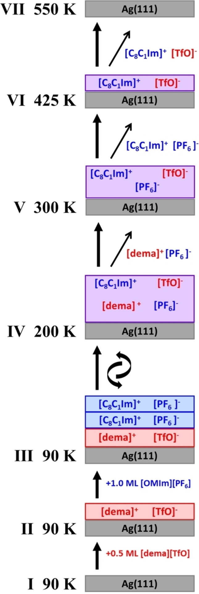
Scheme of the proposed changes in film composition when heating 1 ML [C8C1Im][PF6] on 0.5 ML [dema][TfO] on Ag(111) from 90 to 550 K.
In a first step, we deposited a wetting layer (i. e., 0.5 ML) of [dema][TfO] on clean Ag(111) at a temperature around 90 K. The XP spectra in Figure 5−II show the FCF3 and CCF3 peaks of the [TfO]− anion and the Chetero and Calkyl signals of the [dema]+ cation.[ 14f , 17 ] The Canion:Chetero:Calkyl ratio is 1.0 : 2.8 : 2.2 in 0° and 0.9 : 3.0 : 2.1 in 80°, which is close to the nominal ratio of 1 : 3 : 2 and indicates an intact WL of [dema][TfO] on Ag(111) at low temperature.
After subsequent deposition of 1 ML of [C8C1Im][PF6] on top of the [dema][TfO] WL at around 90 K, the F 1s spectra in Figure 5−III show an additional contribution FPF6 at 687.1 eV related to the [PF6]− anion.[ 14a , 14d , 18 ] The expected nominal FCF3/FPF6 peak ratio in 0° is 0.33. In an simple picture one would expect a ratio of 0.25 (=1 : 4) because [C8C1Im][PF6] has twice the amount of fluorine atoms per IL pair and a twice as thick film was deposited (1.0 vs. 0.5 ML). However, the molecular volume of [C8C1Im][PF6] (0.458 nm3) [23] is higher than for [dema][TfO] (0.305 nm3). [24] Hence, [dema][TfO] has a 1.32 times smaller 2‐dimensional footprint (=V2/3) leading to an expected ratio of 0.33 (=0.25×1.32). This is in excellent agreement with the measured peak ratio FCF3/FPF6 in 0° of 0.33. This ratio changes to 0.27 at 80°, which reflects a substantial decrease of the FCF3 signal. The CCF3 peak at 80° in Figure 5‐III shows a similar substantial attenuation. Both observations indicate that the post‐deposited [C8C1Im][PF6] film covers the [dema][TfO] wetting layer, as is expected for the low deposition temperature of ∼90 K. The Chetero and Calkyl peaks of [C8C1Im][PF6] have only slightly different binding energies than the peaks of the [dema]+ cation. Thus, as for the macroscopic films this means the C 1s peaks of the two cations cannot be deconvoluted. Nevertheless, the qualitative comparison of the C 1s spectra in Figure 5‐III reveals a relative increase of the Calkyl peak as compared to the Chetero peak, when increasing the emission angle from 0° to 80°. This observation further supports our interpretation that the post‐deposited film of [C8C1Im][PF6] (which contains the octyl chains) covers the [dema][TfO] wetting layer.
As a next step, we heated this layered system from 90 to 550 K with a heating rate of 2 K/min and simultaneously recorded TP‐XP spectra in the Ag 3d, F 1s and C 1s regions. The corresponding quantitative analysis of the Ag 3d substrate signal, the FCF3 and FPF6 signals of the two anions, and the combined CCat intensity (related to all carbon atoms of the two cations) is depicted in Figure 6c and 6d for 0° and 80° emission, respectively. For comparison, the thermal evolution of pure [dema][TfO] (for a similar experiment, see also Ref. [14f]) and [C8C1Im][PF6][ 14a , 14c , 18 ] on Ag(111) are shown in Figure 6a and 6b.
Desorption effects – XPS measurements at 0°
We start with the discussion of the data for 0° emission in Figure 5 (top) and Figure 6c, which provide information on the amount of the individual ions in the mixed film, since self‐damping plays only a minor role in this bulk‐sensitive geometry. Notably, all transition or desorption temperatures are determined from the inflection points of the corresponding intensities.
Starting from ∼200 K, the Ag 3d signal (grey circles) shows a small increase (inflection point at ∼235 K), and the FPF6 signal (blue diamonds) and the combined cationic C 1s signals (black triangles) decrease. This behaviour indicates the desorption of the [PF6]− anion and one of the cations. The FCF3 signal (red diamonds) remains constant until much higher temperatures. Since for pure [C8C1Im][PF6] films multilayer desorption occurs only at 405 K,[ 14a , 14d , 18 ] we assume that it is [dema][PF6] which desorbs at this low temperature. The quantitative analysis of the C 1s spectra in Figure 5‐V yields a Calk/Chet ratio of 7.6 : 4.4=1.7, which is very close to the nominal ratio of 7 : 5=1.4 for [C8C1Im]+ (note that for [dema]+ the nominal ratio would be very different, namely 2 : 3=0.67). The observed behaviour indicates complete desorption of [dema]+ cations, with only [C8C1Im]+ remaining in the film. The slightly higher ratio than expected is within the uncertainty of the experiment, due to the low signal to noise ratio.
Upon further heating, the FPF6 signal starts to further decrease at ∼360 K and reaches zero at ∼400 K, which indicates desorption of the remaining [PF6]− as [C8C1Im][PF6]. The decrease of the total surface coverage is also indicated by the step‐like increase of the Ag 3d signal at ∼380 K. The multilayer desorption temperature for pure [C8C1Im][PF6] of ∼405 K[ 14a , 14d , 18 ] is 25 K higher as is evident from comparison to Figure 6b. This lower temperature could indicate that the interaction of [C8C1Im][PF6] with the remaining wetting layer of [C8C1Im][TfO] at the IL/Ag(111) interface is less favorable than in films of pure [C8C1Im][PF6], yielding a lower desorption temperature in case of the mixed thin film. Above 410 K, desorption of [C8C1Im][PF6] is completed and no [PF6]− anions remain on the surface. Based on the previous desorption steps, we expect that above 410 K a new anion‐cation combination, i. e. pure [C8C1Im][TfO], remains as wetting layer, which is formed by on‐surface metathesis at the IL/metal interface. Indeed, the C 1s spectrum of the remaining wetting layer at ∼425 K in Figure 5‐VI (Calk/Chet ratio of 7.4 : 4.6=1.6) is very similar to that of the pure macroscopic film of [C8C1Im][TfO] in Figure S1 (Calk/Chet ratio of 7.1 : 4.9=1.4); both values are very close to nominal value of 7 : 5=1.4. Again, the slightly higher ratio for the thin film is within the uncertainty of the experiment.
The FCF3 signal in 0° emission remains more or less constant from 90 to 440 K, until its subsequent decrease until 550 K indicates the final desorption of the remaining [C8C1Im][TfO]. This decrease in surface coverage is again also reflected in the step‐like increase of the Ag 3d signal at ∼480 K. The higher desorption temperature of ∼480 K for the remaining [C8C1Im][TfO] wetting layer indicates that the adsorption energy of [C8C1Im][TfO] on Ag(111) is larger than that of a [C8C1Im][PF6] wetting layer on Ag(111), where a desorption temperature of ∼445 K is observed (see Figure 6b).[ 14a , 14d , 18 ]
At 550 K, the remaining FFC3 and CCat signals have disappeared in 0°, indicating complete desorption of the formed [C8C1Im][TfO] from Ag(111) (note that in the very surface‐sensitive 80° geometry, remaining traces of decomposition products are detected at the silver surface, see next section). It is interesting to note that neat [dema][TfO] on Ag(111) undergoes significant deprotonation and decomposition at ∼215 K and ∼350 K, respectively. [14f] However, during the thermal evolution of our mixed thin films, we did not observe a similar [dema][TfO] decomposition at all.
Ion exchange and surface enrichment effects – measurements at 80°
Next, we analyze the thermal evolution of the 80° XPS signals in Figure 6d which provide information on the composition of the topmost layer of the mixed film as a function of temperature. Starting at ∼135 K, the FPF6 signal (blue diamonds) starts to decrease and simultaneously the FCF3 signal (red diamonds) starts to increase, both reaching a plateau at ∼200 K. Notably, the corresponding signals did not change in the 0° spectra in Figure 6c, which indicates that none of the respective species is desorbing. We thus propose that between 135 and 200 K, [TfO]− anions at the IL/Ag(111) interface are exchanged by [PF6]− anions and likely are even enriched at the IL/vacuum interface. This conclusion is supported by the analysis of macroscopic mixtures of [dema][TfO] and [C8C1Im][PF6] which indeed show a pronounced preferential enrichment of the [TfO]− anion over the [PF6]− anion (see above). With reference to earlier work on other (purely aprotic) IL mixtures,[ 14c , 14d , 18 ] we propose that the driving force for this exchange is a lower surface tension of the resulting film. Furthermore, it is likely that the octyl chain of the [C8C1Im]+ cation is also enriched at the IL/vacuum interface as found in our macroscopic mixtures discussed above and as it was reported previously for other systems.[ 1d , 14c , 18 , 19 ] To further investigate this assumption, the C 1s spectra in 80° at 90 K (black) and 200 K (orange) are compared in Figure S2. In the absence of enrichment effects one might simply expect the Calkyl contribution to decrease going from 90 to 200 K, since at 90 K the mixed film is frozen with the [C8C1Im]+ cations fixed at the IL/vacuum interface, but upon melting intermixing of the two ILs occurs. Thus, the outermost surface (as the rest of the film) would then be composed of a homogeneous mixture of both ILs with a reduced Calkyl content compared to the starting point. However, by comparing both spectra in Figure S2, the Calkyl contribution at 200 K stays nearly unchanged. We thus propose that the octyl chains of the [C8C1Im]+ cations remain enriched after the first anion exchange process starting from ∼135 K. The IL exchange and enrichment of the [TfO]− anion can also be observed via the increased CCF3 signal at 200 K in the C 1s spectrum in Figure S2.
The melting point of bulk [dema][TfO] is 260 K [3a] and the glass transition of [C8C1Im][PF6] occurs at about 195 K. [25] In agreement with the interpretation for other ILs in previous studies,[ 14c , 14d , 18 ] we conclude that the phase transition of the IL on top determines the mobility of individual ions in the mixed IL film.
Upon further heating, FPF6 shows a next stepwise decrease at ∼243 K to a new plateau between 270 and 350 K. The Ccat signals also decrease, but over a wider temperature range starting around ∼180 K, which is attributed to continuous reorientation effects of the octyl chains at the outer surface.[ 14c , 14d ] In combination with the 0° data, we attribute this decrease of both signals to the desorption of [dema][PF6]. The C 1s spectra of the remaining IL at ∼300 K (Figure 6‐V) shows a Calk/Chet ratio of 8.1 : 3.5=2.3 as compared to the nominal ratio of 7 : 5=1.4. This further corroborates the enrichment of octyl chains at the IL/vacuum interface of the thin film. Notably, the Calk/Chet ratio in macroscopic films is 10.0 : 4.4=2.3 for [C8C1Im][PF6] (see Table S1 and Figure S1) and 8.8 : 4.4=2.0 for [C8C1Im][TfO] (see Figure S1) in 80°. Together with the conclusions derived from the 0° data, the observed behaviour indicates that between 270 and 350 K the IL film contains only [C8C1Im]+ cations with surface‐enriched octyl chains (see also results for macroscopic mixtures).
The following stepwise decrease of the FPF6 signal at ∼385 K occurs similarly to the 0° data, and is due to desorption of [C8C1Im][PF6], leaving only a [C8C1Im][TfO] wetting layer at the silver surface. Upon desorption of [C8C1Im][PF6], we also observe a slight increase of the FCF3 signal in 80°, which is not visible in 0°. This gain of [TfO]− at the outer surface is attributed to the fact that in the remaining wetting layer above 385 K, all [TfO]− anions are necessarily part of the outermost surface layer, whereas below this temperature, also [PF6]− anions are present at the IL/vacuum interface. Notably, for the remaining [C8C1Im][TfO] wetting layer at ∼425 K (Figure 5‐VI) at 80° the Calk/Chet ratio is 6.8 : 4.9=1.4. This value is very close to the nominal value of 7 : 5=1.4, but is much lower than the value of 2.3 at ∼300 K (see above) in Figure 5‐V. Possible reasons are loss of order at this elevated temperature due to entropy effects or a different adsorption geometry in the WL (at this temperature).
In line with the 0° data, the decrease of the FCF3 signal at ∼475 K indicates desorption of [C8C1Im][TfO]. The minor remaining signal at 550 K could be due to some small amounts of a dissociation product, which is only visible in the very surface sensitive 80° geometry.
As a last point, we want to address the observation that in addition to the discussed changes in peak intensities, we also observe shifts of the F 1s and C 1s peaks upon heating the layered IL film. These shifts are evident in the spectra at 0° (Figure 5, top) but also in the spectra at 80° (Figure 5, bottom). They are assigned to a combination of initial and final state effects as a result of the changing local environment. [14b] From 90 to 200 K, the FCF3 and FPF6 signals shift to lower binding energy by 0.3 eV, which is attributed to the reorientation and surface enrichment of the alkyl chains at the outermost surface, covering the anions. The shift of the FCF3 and FPF6 signals by 0.5–0.6 eV to lower binding energy between 200 and 300 K results from the change of the chemical composition of the film due to the desorption of an equivalent of 0.5 ML [dema][PF6]. The same explanation likely holds for the minor shift of all F 1s anion and C 1s cation signals by 0.1–0.2 eV to lower binding energy between 300 and 425 K.
Summary and Conclusions
We investigated the adsorption and thermal evolution of ultrathin mixed films of the protic IL ([dema][TfO]) and the aprotic IL ([C8C1Im][PF6]) on Ag(111) by angle‐resolved X‐ray photoelectron spectroscopy (ARXPS). As first step, we characterized the IL/vacuum interface of ∼0.1 mm thick films of various macroscopic mixtures of [dema][TfO] and [C8C1Im][PF6] that serve as a reference for the investigation of the ultrathin films. For each mixture, we find that the [TfO]− anions and the [C8C1Im]+ cations are enriched at the IL/vacuum interface. The latter are also enriched for the neat [C8C1Im][PF6] thin films.
Based on these findings, we then investigated ultrathin mixed IL films. We sequentially deposited 0.5 ML of [dema][TfO] and 1.0 ML [C8C1Im][PF6] on Ag(111) at about 90 K, and heated this film to 550 K while monitoring the film composition by ARXPS. Thereby, bulk‐sensitive measurements at 0° allow for determining the overall film composition and changes thereof by selective desorption, while surface‐sensitive measurements at 80° provide insight into enrichment and exchange processes at the IL‐vacuum and the IL‐metal interfaces. Between 135 and 200 K, the exchange of the [TfO]− anions at the Ag(111) surface by [PF6]− anions occurs, yielding an enrichment of the [TfO]− anions at the IL/vacuum interface together with the [C8C1Im]+ cations. Subsequently, [dema][PF6] selectively desorbs at ∼235 K, and [C8C1Im][PF6] at ∼380 K. Hereby, a wetting layer of pure [C8C1Im][TfO] forms by on‐surface metathesis at the IL/metal interface. Finally, this [C8C1Im][TfO] layer desorbs more or less completely at ∼480 K leaving the Ag(111) surface behind. The here reported enrichment, exchange and desorption processes leading to the on‐surface metathesis of ultrathin IL layers on solid supports might open a novel route for the on‐surfaces synthesis of new ultrathin coatings with ILs, which cannot be prepared by physical vapor deposition.
Experimental Section
The synthesis and characterization of [dema][TfO] was described in Ref. [54] [C8C1Im][PF6] was purchased from Sigma‐Aldrich (purity >95 %). Both ILs were carefully degassed in UHV before depositing them via physical vapor deposition (PVD) in UHV from a modified Knudsen cell with a boron nitride crucible. The details of the Knudsen cell have been published in Ref. [14c] [dema][TfO] and [C8C1Im][PF6] were deposited at cell temperatures of 345 and 448 K, respectively. The IL flux was monitored with a quartz crystal microbalance before and after deposition to ensure a constant evaporation rate. In former studies, [dema][TfO] [14f] and [C8C1Im][PF6][ 14a , 14d , 18 ] showed no signs of decomposition upon deposition on Ag(111) at 90 K.
The Ag(111) single crystal with circular shape and diameter of 15 mm was purchased from MaTeck (purity 99.999 %, polished with an alignment better than 0.1° to the (111) plane). It was cleaned by short heating to >500 K and subsequent Ar+ sputtering (600 V, 8 μA, 30 min) at RT followed by annealing (800 K, 10 min). The temperature was measured using a type K thermocouple put into a 0.5 mm wide pinhole of the single crystal, with an absolute accuracy of ±20 K (500 K) and a reproducibility of ±2 K.
The UHV system for angle‐resolved X‐ray photoelectron spectroscopy (ARXPS) contains a non‐monochromated Al K X‐ray source (SPECS XR 50, 1486.6 eV, 240 W) and a hemispherical electron analyzer (VG SCIENTA R3000) (described in more detail in Ref. [14e] ). A pass energy of 100 eV was applied for all spectra, yielding an overall energy resolution of about 0.9 eV. [14e] The spectra were quantitatively evaluated using CasaXPS V2.3.16Dev6. For the Ag 3d spectra, a Shirley background [26] was subtracted and peaks were fitted with Lorentzian line shapes. For the F 1s, C 1s, O 1s, S 2p and N 1s regions, linear backgrounds were subtracted and the peaks were fitted with Voigt profiles (30 % Lorentzian contribution). For the macroscopic [C8C1Im][PF6] and [C8C1Im][TfO] films, the XPS binding energy (BE) scale was calibrated by setting Calkyl peak to 285.0 eV, [27] which yielded a BE of FCF3 peak of the [TfO]− anion of 688.5 eV. [17] XP spectra of the macroscopic film of [dema][TfO] were referenced to this value of FCF3 at 688.5 eV. [17] Furthermore, all macroscopic mixtures of [dema][TfO] and [C8C1Im][PF6] were referenced to Calkyl at 285.0 eV. [27] The spectra of ultrathin films were referenced to the Fermi edge yielding 368.20 eV for Ag 3d5/2. In agreement with literature,[ 14b , 14c , 14d , 14e , 17b , 17c , 18 ] we fitted the C 1s components related to the [dema]+ and [C8C1Im]+ cations with two contributions, Chetero for the carbon atoms directly bonded to a nitrogen (hetero) atom, and Calkyl for the alkyl carbon atoms further away from the central nitrogen atom. In addition, we applied a constraint for peak widths as used before: fwhm(Chetero)=1.11 ⋅ fwhm(Calkyl).[ 14b , 14c , 14d , 14e , 18 ] Furthermore, we subtracted a residual carbon contamination signal that could not be removed even after repeated cleaning cycles.
The coverage of [dema][TfO] and [C8C1Im][PF6] on Ag(111) was determined by measuring the attenuation of the Ag 3d substrate signal at an emission angle of ϑ=0° according to Lambert‐Beer's Law (Eq. 1), where d is the film thickness, ϑ is the emission angle, λ is the mean free path, I0 and Id are the intensity of the clean and IL covered substrate signal, respectively. The interface composition was analysed by comparing 0° and 80° data. By using Kα radiation, the information depth (ID) at an emission angle of ϑ=0° is 7–9 nm (depending on the kinetic energy). At ϑ=80°, the ID reduces to 1–1.5 nm, which means that only the topmost surface layers are probed. The ID is defined as 3 times the inelastic mean free path (λ) of an Ag 3d electron (∼1.1 keV) and is 2.5 nm in IL films.[ 14a , 14c , 14d , 14e , 18 ]
| (1) |
We use the definition of a monolayer (1 ML) of IL of a bilayer of cation and anion irrespective of their relative arrangement. The monolayer height h of [dema][TfO] and [C8C1Im][PF6] was calculated from the respective molecular volume based on density values ρ from literature as described previously.[ 14a , 28 ] We obtain for [C8C1Im][PF6] h=0.77 nm (ρ=1.23 g/cm3) [23] and for [dema][TfO] h=0.67 nm (ρ=1.29 g/cm3). [24]
Conflict of interest
The authors declare no conflict of interest.
1.
Supporting information
As a service to our authors and readers, this journal provides supporting information supplied by the authors. Such materials are peer reviewed and may be re‐organized for online delivery, but are not copy‐edited or typeset. Technical support issues arising from supporting information (other than missing files) should be addressed to the authors.
Supporting Information
Acknowledgements
S.M., M.L. and H.‐P.S. thank the European Research Council (ERC) for support through an Advanced Investigator Grant (ILID 693398) to HPS, and the DFG for support through Collaborative Research Center (CRC)/Sonderforschungsbereich (SFB) 1452. Open Access funding enabled and organized by Projekt DEAL.
S. Massicot, T. Sasaki, M. Lexow, F. Maier, S. Kuwabata, H.-P. Steinrück, Chem. Eur. J. 2022, 28, e202200167.
Data Availability Statement
The data that support the findings of this study are available from the corresponding author upon reasonable request.
References
- 1.
- 1a. Welton T., Chem. Rev. 1999, 99, 2071–2084; [DOI] [PubMed] [Google Scholar]
- 1b. Binnemans K., Chem. Rev. 2005, 105, 4148–4204; [DOI] [PubMed] [Google Scholar]
- 1c.P. Wasserscheid, T. Welton in: Ionic Liquids in Synthesis, Second Edition (Eds: P. Wasserscheid, T. Welton), Wiley-VCH Verlag GmbH & Co. KGaA, 2007;
- 1d. Lovelock K. R. J., Villar-Garcia I. J., Maier F., Steinrück H.-P., Licence P., Chem. Rev. 2010, 110, 5158–5190; [DOI] [PubMed] [Google Scholar]
- 1e. Kolbeck C., Lehmann J., Lovelock K. R. J., Cremer T., Paape N., Wasserscheid P., Fröba A. P., Maier F., Steinrück H. P., J. Phys. Chem. B. 2010, 114, 17025–17036; [DOI] [PubMed] [Google Scholar]
- 1f. Steinrück H.-P., Libuda J., Wasserscheid P., Cremer T., Kolbeck C., Laurin M., Maier F., Sobota M., Schulz P. S., Stark M., Adv. Mater. 2011, 23, 2571–2587; [DOI] [PubMed] [Google Scholar]
- 1g. Hayes R., Warr G. G., Atkin R., Chem. Rev. 2015, 115, 6357–6426. [DOI] [PubMed] [Google Scholar]
- 2.
- 2a. Lewandowski A., Świderska-Mocek A., J. Power Sources 2009, 194, 601–609; [Google Scholar]
- 2b. Meng T., Young K.-H., Wong D. F., Nei J., Batteries 2017, 3, 4; [Google Scholar]
- 2c. Yang Q., Zhang Z., Sun X.-G., Hu Y.-S., Xing H., Dai S., Chem. Soc. Rev. 2018, 47, 2020–2064; [DOI] [PubMed] [Google Scholar]
- 2d. Yang G., Song Y., Wang Q., Zhang L., Deng L., Mater. Des. 2020, 190, 108563. [Google Scholar]
- 3.
- 3a. Nakamoto H., Watanabe M., Chem. Commun. 2007, 2539–2541; [DOI] [PubMed] [Google Scholar]
- 3b. Lee S.-Y., Ogawa A., Kanno M., Nakamoto H., Yasuda T., Watanabe M., J. Am. Chem. Soc. 2010, 132, 9764–9773; [DOI] [PubMed] [Google Scholar]
- 3c. Yasuda T., Watanabe M., MRS Bull. 2013, 38, 560–566; [Google Scholar]
- 3d. Greaves T. L., Drummond C. J., Chem. Rev. 2015, 115, 11379–11448. [DOI] [PubMed] [Google Scholar]
- 4.
- 4a. Poonam G., Singh R., in: Applications of Nanotechnology for Green Synthesis (Eds.: A. M. Asiri Inamuddin,), Springer, Cham, 2020, p. 41–62; [Google Scholar]
- 4b. Handy S. T., Zhang X., Org. Lett. 2001, 3, 233–236; [DOI] [PubMed] [Google Scholar]
- 4c. Sawant A. D., Raut D. G., Darvatkar N. B., Salunkhe M. M., Green Chem. Lett. Rev. 2011, 4, 41–54. [Google Scholar]
- 5.
- 5a. Wegner S., Janiak C., in: Ionic Liquids II (Eds.: Kirchner B., Perlt E.), Springer, Cham, 2018, pp. 153–184; [Google Scholar]
- 5b. Richter K., Campbell P., Baecker T., Schimitzek A., Yaprak D., Mudring A.-V., Phys. Status Solidi B 2013, 250, 1152–1164; [Google Scholar]
- 5c. Sasaki T., Uematsu T., Tsuda T., Kuwabata S., Electrochemistry 2018, 86, 223–225; [Google Scholar]
- 5d. Tsuda T., Kurihara T., Hoshino Y., Kiyama T., Okazaki K.-i., Torimoto T., Kuwabata S., Electrochemistry 2009, 77, 693–695. [Google Scholar]
- 6.
- 6a. Wasserscheid P., Keim W., Angew. Chem. Int. Ed. 2000, 39, 3772–3789; [DOI] [PubMed] [Google Scholar]; Angew. Chem. 2000, 112, 3926–3945; [Google Scholar]
- 6b. Breitenlechner S., Fleck M., Müller T. E., Suppan A., J. Mol. Catal. A 2004, 214, 175–179; [Google Scholar]
- 6c. Riisager A., Fehrmann R., Flicker S., van Hal R., Haumann M., Wasserscheid P., Angew. Chem. Int. Ed. 2005, 44, 815–819; [DOI] [PubMed] [Google Scholar]; Angew. Chem. 2005, 117, 826–830; [Google Scholar]
- 6d. Kernchen U., Etzold B., Korth W., Jess A., Chem. Eng. Technol. 2007, 30, 985–994; [Google Scholar]
- 6e. Virtanen P., Salmi T., Mikkola J.-P., Ind. Eng. Chem. Res. 2009, 48, 10335–10342; [Google Scholar]
- 6f. Haumann M., Schönweiz A., Breitzke H., Buntkowsky G., Werner S., Szesni N., Chem. Eng. Technol. 2012, 35, 1421–1426. [Google Scholar]
- 7.
- 7a. Lovelock K. R. J., R. Soc. Open Sci. 2017, 4, 171223; [DOI] [PMC free article] [PubMed] [Google Scholar]
- 7b. Earle M. J., Esperança J. M. S. S., Gilea M. A., Canongia Lopes J. N., Rebelo L. P. N., Magee J. W., Seddon K. R., Widegren J. A., Nature 2006, 439, 831–834; [DOI] [PubMed] [Google Scholar]
- 7c. Ravula S., Larm N., Mottaleb M. A., Heitz M., Baker G., Chem. Eng. 2019, 3, 1–12. [Google Scholar]
- 8.
- 8a. Cao Y., Mu T., Ind. Eng. Chem. Res. 2014, 53, 8651–8664; [Google Scholar]
- 8b. Maton C., De Vos N., Stevens C. V., Chem. Soc. Rev. 2013, 42, 5963–5977; [DOI] [PubMed] [Google Scholar]
- 8c. Huang Y., Chen Z., Crosthwaite J. M., Aki S. N. V. K., Brennecke J. F., J. Chem. Thermodyn. 2021, 161, 106560; [Google Scholar]
- 8d. Cassity C., Mirjafari A., Mobarrez N., Strickland K., O′Brien R., Davis J., Chem. Commun. 2013, 49, 7590–7592. [DOI] [PubMed] [Google Scholar]
- 9.
- 9a. Seddon K. R., Nat. Mater. 2003, 2, 363–365; [DOI] [PubMed] [Google Scholar]
- 9b. Plechkova N. V., Seddon K. R., Chem. Soc. Rev. 2008, 37, 123–150. [DOI] [PubMed] [Google Scholar]
- 10.
- 10a. Bartlewicz O., Dąbek I., Szymańska A., Maciejewski H., Catalysts 2020, 10, 1227; [Google Scholar]
- 10b. Korth W., Jess A., in: Supported Ionic Liquids (Eds.: Rasmus F., Riisager A., Haumann M.), Wiley-VCH Verlag GmbH & Co. KGaA, 2014, p. 279–306. [Google Scholar]
- 11.
- 11a. Miller S. F., Friedrich H. B., Holzapfel C. W., ChemCatChem 2012, 4, 1337–1344; [Google Scholar]
- 11b. Schwab F., Weidler N., Lucas M., Claus P., Chem. Commun. 2014, 50, 10406–10408; [DOI] [PubMed] [Google Scholar]
- 11c. Zhang G.-R., Munoz M., Etzold B. J. M., Angew. Chem. Int. Ed. 2016, 55, 2257–2261; [DOI] [PubMed] [Google Scholar]; Angew. Chem. 2016, 128, 2298–2302; [Google Scholar]
- 11d. Antonels N. C., Meijboom R., Catal. Commun. 2014, 57, 148–152. [Google Scholar]
- 12.
- 12a.J. K. Smith, in: Encyclopedia of Catalysis (Ed.: I. Horáth), John Wiley & Sons, Inc., 2002;
- 12b. Armor J. N., Catal. Today 2011, 163, 3–9. [Google Scholar]
- 13.
- 13a. Austen Angell C., Ansari Y., Zhao Z., Faraday Discuss. 2012, 154, 9–27; [DOI] [PubMed] [Google Scholar]
- 13b. Lei Z., Chen B., Yoon-Mo K., MacFarlane D. R., Chem. Rev. 2017, 117, 6633–6635. [DOI] [PubMed] [Google Scholar]
- 14.
- 14a. Lexow M., Maier F., Steinrück H.-P., Adv. Phys. 2020, 5, 1761266; [Google Scholar]
- 14b. Cremer T., Stark M., Deyko A., Steinrück H. P., Maier F., Langmuir 2011, 27, 3662–3671; [DOI] [PubMed] [Google Scholar]
- 14c. Lexow M., Heller B. S. J., Maier F., Steinrück H.-P., ChemPhysChem 2018, 19, 2978–2984; [DOI] [PMC free article] [PubMed] [Google Scholar]
- 14d. Lexow M., Heller B. S. J., Partl G., Bhuin R. G., Maier F., Steinrück H.-P., Langmuir 2019, 35, 398–405; [DOI] [PMC free article] [PubMed] [Google Scholar]
- 14e. Lexow M., Talwar T., Heller B. S. J., May B., Bhuin R. G., Maier F., Steinrück H.-P., Phys. Chem. Chem. Phys. 2018, 20, 12929–12938; [DOI] [PMC free article] [PubMed] [Google Scholar]
- 14f. Massicot S., Sasaki T., Lexow M., Shin S., Maier F., Kuwabata S., Steinrück H.-P., Langmuir 2021, 37, 11552–11560; [DOI] [PMC free article] [PubMed] [Google Scholar]
- 14g. Uhl B., Huang H., Alwast D., Buchner F., Behm R. J., Phys. Chem. Chem. Phys. 2015, 17, 23816–2332; [DOI] [PubMed] [Google Scholar]
- 14h. Buchner F., Forster-Tonigold K., Uhl B., Wagner N., Farkhondeh H., Groß A., Behm R. J., ACS Nano 2013, 7, 7773–7784. [DOI] [PubMed] [Google Scholar]
- 15. Srour H., Rouault H., Santini C. C., Chauvin Y., Green Chem. 2013, 15, 1341–1347. [Google Scholar]
- 16. Uhl B., Cremer T., Roos M., Maier F., Steinrück H.-P., Behm R. J., Phys. Chem. Chem. Phys. 2013, 15, 17295–17302. [DOI] [PubMed] [Google Scholar]
- 17.
- 17a. Fogarty R. M., Matthews R. P., Ashworth C. R., Brandt-Talbot A., Palgrave R. G., Bourne R. A., Hoogerstraete T. V., Hunt P. A., Lovelock K. R. J., J. Chem. Phys. 2018, 148, 193817; [DOI] [PubMed] [Google Scholar]
- 17b. Fogarty R. M., Palgrave R. G., Bourne R. A., Handrup K., Villar-Garcia I. J., Payne D. J., Hunt P. A., Lovelock K. R. J., Phys. Chem. Chem. Phys. 2019, 21, 18893–18910; [DOI] [PubMed] [Google Scholar]
- 17c. Fogarty R. M., Rowe R., Matthews R. P., Clough M. T., Ashworth C. R., Brandt A., Corbett P. J., Palgrave R. G., Smith E. F., Bourne R. A., Chamberlain T. W., Thompson P. B. J., Hunt P. A., Lovelock K. R. J., Faraday Discuss. 2018, 206, 183–201. [DOI] [PubMed] [Google Scholar]
- 18. Lexow M., Massicot S., Maier F., Steinrück H.-P., J. Phys. Chem. C 2019, 123, 29708–29721. [DOI] [PMC free article] [PubMed] [Google Scholar]
- 19. Lovelock K. R. J., Phys. Chem. Chem. Phys. 2012, 14, 5071–5089. [DOI] [PubMed] [Google Scholar]
- 20.
- 20a. Heller B., Kolbeck C., Niedermaier I., Dommer S., Schatz J., Hunt P., Maier F., Steinrück H.-P., ChemPhysChem 2018, 19, 1733–1745; [DOI] [PMC free article] [PubMed] [Google Scholar]
- 20b. Heller B., Lexow M., Greco F., Shin S., Partl G. J., Maier F., Steinrück H.-P., Chem. Eur. J. 2019, 26, 1117–1126. [DOI] [PMC free article] [PubMed] [Google Scholar]
- 21. Freire M. G., Carvalho P. J., Fernandes A. M., Marrucho I. M., Queimada A. J., Coutinho J. A. P., J. Colloid Interface Sci. 2007, 314, 621–630. [DOI] [PubMed] [Google Scholar]
- 22. Martino W., de la Mora J. F., Yoshida Y., Saito G., Wilkes J., Green Chem. 2006, 8, 390–397. [Google Scholar]
- 23.
- 23a. Deyko A., Lovelock K., Corfield J.-A., Taylor A., Gooden P., Villar-Garcia I., Licence P., Jones R., Krasovskiy V., Chernikova E., Kustov L., Phys. Chem. Chem. Phys. 2009, 11, 8544–8555; [DOI] [PubMed] [Google Scholar]
- 23b. Dzyuba S., Bartsch R., ChemPhysChem 2002, 3, 161–166; [DOI] [PubMed] [Google Scholar]
- 23c. Gu Z., Brennecke J. F., J. Chem. Eng. Data 2002, 47, 339–345. [Google Scholar]
- 24.
- 24a. Atilhan M., Anaya B., Ullah R., Costa L. T., Aparicio S., J. Phys. Chem. C 2016, 120, 17829–17844; [Google Scholar]
- 24b. Miran M. S., Yasuda T., Tatara R., Abu Bin Hasan Susan M., Watanabe M., Faraday Discuss. 2018, 206, 353–364. [DOI] [PubMed] [Google Scholar]
- 25. Huddleston J. G., Visser A. E., Reichert W. M., Willauer H. D., Broker G. A., Rogers R. D., Green Chem. 2001, 3, 156–164. [Google Scholar]
- 26. Shirley D. A., Phys. Rev. B 1972, 5, 4709–4714. [Google Scholar]
- 27. Cremer T., Kolbeck C., Lovelock K., Paape N., Wölfel R., Schulz P., Wasserscheid P., Weber H., Thar J., Kirchner B., Maier F., Steinrück H.-P., Chem. Eur. J. 2010, 16, 9018–9033. [DOI] [PubMed] [Google Scholar]
- 28. Cremer T., Killian M., Gottfried J. M., Paape N., Wasserscheid P., Maier F., Steinrück H.-P., ChemPhysChem 2008, 9, 2185–2190. [DOI] [PubMed] [Google Scholar]
Associated Data
This section collects any data citations, data availability statements, or supplementary materials included in this article.
Supplementary Materials
As a service to our authors and readers, this journal provides supporting information supplied by the authors. Such materials are peer reviewed and may be re‐organized for online delivery, but are not copy‐edited or typeset. Technical support issues arising from supporting information (other than missing files) should be addressed to the authors.
Supporting Information
Data Availability Statement
The data that support the findings of this study are available from the corresponding author upon reasonable request.