Abstract
Direct synthesis of N‐containing organic compounds from dinitrogen (N2) can make synthetic chemistry more sustainable. Previous bottlenecks in lithium‐mediated N2 fixation were resolved by loading Li‐metal anodes covered with the typical Li+ ion‐conducting solid electrolyte interface, which are subsequently allowed to react with N2. The developed strategy allowed us to reach high Faradaic efficiencies toward Li3N. These reactive Li3N were then contacted with acylchlorides. Surface nitride ions are more nucleophilic than amines which direct the two C−N coupling reactions toward formation of imides rather than amides, and an integrated current efficiency of 57–77 % could be realized. This study thereby not only provides a feasible electrochemical Li3N synthesis, but also delineates an economical and green synthesis of highly valuable N‐containing compounds from N2 under mild conditions, just using commercial spare parts and processes from the omnipresent Li battery technology.
Keywords: C−N Coupling Reactions, Imides, Li3N, N2 Fixation, Solid Electrolyte Interface
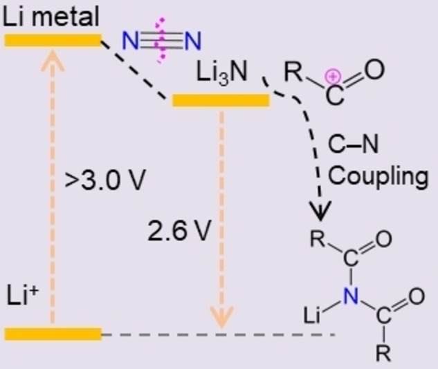
A successive reaction that yields aryl imides through combining lithium‐mediated N2 fixation and C−N coupling is reported. Instead of simply being hydrolyzed to NH3 with energy wasted, this work first focuses on electro‐synthetic Li3N from N2‐fixation for the direct synthesis of nitrogen‐containing chemicals, which will compensate for the energy consumption of Li plating and make the electrochemical N2 fixation more economical.
Electrochemical synthesis of chemicals is an actual topic as it represents a future sustainable alternative to traditional thermochemical methods.[ 1 , 2 , 3 , 4 , 5 , 6 ] The electrochemical N2 reduction reaction (eNRR) by transfer of electrons and protons directly into the N2 molecule is inspired by the enzyme nitrogenase of bacteria in Nature and was already demonstrated to be feasible under mild conditions. [7] Electrochemical synthesis of NH3 indeed may help to overcome some of the issues associated with the traditional Haber–Bosch process. [8] However, these methods rarely consider the immediate use of the as‐generated activated nitrogen species from N2 splitting for the subsequent synthesis of nitrogen‐containing chemicals, which is actually an aspirational target in chemistry.[ 9 , 10 ] Very recently, an experimental realization of an electrochemical C−N coupling reaction using N2 and CO2 as feedstocks to generate urea was demonstrated, which we consider as the conceptual door opener for the direct production of nitrogen‐containing chemicals using inert N2 as nitrogen source under mild conditions. [11] However, similar to eNRR, this process is subject to a poor rate (0.7 μmol h−1 cm−2) and still low Faradaic efficiency (FE=8.9 %), mostly due to the difficulties of N2 activation in the presence of the otherwise dominant H2 evolution reaction.[ 12 , 13 , 14 , 15 ] Therefore, development of efficient methods to electro‐synthesize nitrogen‐containing chemicals directly from N2 are still highly desired. Among various methods for electrochemical N2 fixation, the Li‐mediated method can generate NH3 with improved rates (>1 μmol h−1 cm−2) and FEs (>10 %). The practicality of Li‐mediated methods of N2 fixation was controversially discussed in recent years, because it requires first a highly negative potential to plate the Li metal, which is overspending about 3 Volts or 300 kJ mol−1 energy when only ammonia is the target. [16]
In this context, it is worth reminding that the primary product of the cathode nitridation, Li3N, is only slightly more electropositive than Li (oxidation potential +0.44 V versus Li/Li+). [17] Thereby the loss of energy in this primary step of nitrogen fixation is only minor and just of the right magnitude to drive the reaction to high yields and high efficacies. Li3N is thereby a strong reductant, very nucleophilic, and the energy consumed during the electrochemical reduction of lithium is still stored in a highly reactive compound, which can be used in synthesis, [18] which otherwise with amines would be uphill organic syntheses. Therefore, instead of simple hydrolysis to NH3, this work focuses on other nucleophilic reactions of Li3N for the direct synthesis of high‐value nitrogen‐containing organic molecules, and we chose the case of imides to illustrate how much higher value from electrochemical N2 fixation could be generated.
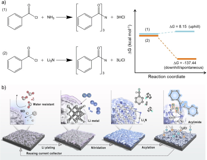
Imides are highly important organic structures that are extensively found in various pharmaceuticals, natural products, and electrically conductive materials.[ 19 , 20 ] Present methods for synthesis of imides most frequently utilize acylation of amides with acid chlorides in the presence of super‐stoichiometric amounts of strong bases.[ 21 , 22 ] Amides again are synthesized from the acylation of ammonia or primary amines with activated forms of carboxylic acids, such as acid chlorides, anhydrides, and esters. [23] In this two‐step approach, external bases are used to bind the evolved HCl and in turn to shift equilibrium to the formation of imide. Substitution of ammonia with Li3N interestingly eliminates the need for an external base as the expelled chloride anion is bound by Li+ into LiCl, which then can be looped into the formation of Li3N again. For all the discussed reasons, acylation of Li3N is a downhill process, while acylation of NH3 (in the absence of the exogenous base) is uphill (Figure 1a).
Figure 1.
a) Elucidation of the advantage of substitution of ammonia with Li3N for synthesis of aryl imides in terms of thermodynamics (free energy change (ΔG)). Blue lines correspond to Equation (1), uphill; brown lines to Equation (2), downhill. b) Schematic depiction of the individual steps, including Li electroplating, nitridation, and acylation, for synthesis of aryl imides.
Following these arguments, we report here the synthesis of aryl imides through the combination of electrochemical lithium plating, N2 fixation on these electrodes in a non‐electrochemical conversion process, and the final spontaneous C−N coupling reaction between Li3N and aryl acid chlorides (Figure 1b). Key in this process turned out to be a battery‐inspired solvent‐adjustment strategy to form the appropriate solid electrolyte interface (SEI). The as‐formed SEI enhances the Faradaic efficiency (FE) of Li plating in the first step and enables and moderates the subsequent reaction with N2. The process has a maximum FE of 84.6 % for N2 fixation to form Li3N and a calculated FE of 57–77 % toward arylimides after acylation of Li3N by aryl acid chlorides. A computer model is presented where the aryl imides are formed at the Li2N layer termination via a C−N coupling reaction, where two Li atoms are spontaneously replaced by two aromatic acyl groups at ambient conditions.
Nitride generation in the first step must meet the requirements of high formation rate, high FE, and having no need for purification to improve the overall integrated efficiency and reduce the number of steps in the synthesis of N‐containing compounds. The Li‐mediated N2 reduction method is composed of two successive stages: 1) Li plating, and 2) nitridation with gaseous N2.[ 24 , 25 ] In terms of Li plating, in industry the process is typically conducted at 400–450 °C by electrolysis of LiCl–KCl eutectic. Such conditions make the process extremely energy‐intensive and do not qualify this method to replace the traditional Haber–Bosch process of N2 fixation. [26] Thus, we chose a standard battery system operating at ambient conditions.[ 27 , 28 ] The biggest problem in this approach are side reactions that occur during the first Li‐plating process, where fresh metallic Li hydrolyzes upon contact with a spurious amount of water in the solvent or reacts with the ester‐type cosolvent to form the SEI. SEI formation is wanted, separates the metallic Li from the solvent phase, and has been over the many years of Li‐metal batteries nicely optimized.
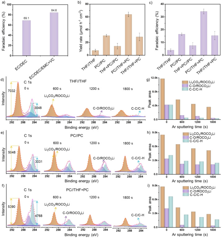
SEI formation is in the context of the present conversion electrodes more complicated than in Li batteries, as we apply comparably larger volumes of electrolyte and rather high current densities up to 5 mA cm−2. [29] Therefore, current experiments require ultralow absolute water content of the solvents, such as solvents distilled from sodium metal, the use of a small volume of electrolyte (1.75 mL each electrode compartment as compared to 180 μL in a battery), as well as electrolytes prepared in an inert‐gas‐protected glove box, to avoid excessive SEI generation.[ 30 , 31 , 32 , 33 ] The small two‐electrode cells contain a Cu foil electrode (1.13 cm2), separator, electrolyte, and lithium foil as counter electrode, and were assembled in a glove box filled with pure Ar (Figure S1). The electrolytes used in the experiments were a standard ester‐type electrolyte 1 M LiPF6/ethylene carbonate/diethyl carbonate (EC:DEC=1 : 1) by volume with or without 2 wt % vinylene carbonate (VC) additive. The Ester‐type electrolyte is copied from battery optimizations because it can effectively prevent the formation of lithium dendrites under relatively high current (−5 mA) (Figure S2). [34] Minor addition of VC stabilizes already thin SEI layers to obtain higher primary Coulombic efficiency of 91.5 % for Li plating/stripping and a further FE of 84.6 % for Li3N synthesis at a current of −2.5 mA (Figures 2a and S4). The VC‐free still provides a Coulombic efficiency of 85.5 % and FE of 69.1 % (Figures S3, S5). The FE reported here are higher than most previously reported values of N2 electro‐reduction experiments by a lithium‐mediated method (Table S1).
Figure 2.
a) Faradaic efficiencies of the Li3N synthesis in a battery system at a current of −2.5 mA using an electrolyte of 1 M LiPF6/EC:DEC=1 : 1 by volume and 1 M LiPF6/EC:DEC:EMC=1 : 1 : 1 by volume with 2 wt % VC additive. b) Yield rates and c) the Faradaic efficiencies of Li3N after plating in a large electrolytic cell using different electrolyte systems at a current density of −15 mA cm−2. Error bars denote the standard deviations of yield rate and the Faradaic efficiencies calculated from three independent experiments. C 1s XPS conducted on SSM electrodes after plating Li in d) THF//THF, e) PC//PC, and f) PC/THF+PC systems with various Ar+‐sputtering intervals. g)–i) The peak areas of different components obtained after the etching for a specified period of time. Values were obtained by integrating the components of the peak signals of SSM electrodes after plating Li in g) THF//THF, h) PC//PC, and i) PC//THF+PC systems.
The use of large electrolytic cells to realize larger currents and higher capacities, as in batteries, can make the method more practical. The appropriate SEI layer construction to prevent excessive Li‐loss to side reactions becomes, due to transport effects, more important (Figure S6). Here, we used THF as an optional additive, which is considered unsafe in Li batteries. The Li plating process was then conducted in a two‐compartment electrochemical cell separated by a polyethylene membrane (PE, 16 μm thick), and the solvent systems in the cathode and anode compartments were allowed to interpenetrate slowly.
When the electrochemical cell operated using an electrolyte (PC//THF+PC) composed of 12 mL of pure PC‐based catholyte and 12 mL of a mixed‐solvent‐(PC:THF=1 : 1)‐based anolyte, larger amounts of Li could be plated on the stainless‐steel mesh substrate (1 cm2, Figures S7, S8). After the final nitridation process under a N2 atmosphere (Figure S9), a FE of 34.3±1.9 % and yield rate of 63.9±3.6 μmol h−1 cm−2 for Li3N were calculated even at the very high current density of −15 mA cm−2 (Figures 2b,c and S10–S14). This is the typical compromise of electrochemistry: with increasing rates energy losses and side reactions increase (Figure S15).
In the case of Li plating in large electrolytic cells, the relationship between SEI structure and the possibility of N2 fixation was studied in detail. In a nitrogen conversion electrode, the SEI must avoid solvent–metal contacts, but allow both Li+ and N2 to permeate. An appropriate amount of non‐reactive THF in the solvent is thereby important to improve the performance of the electrolyzer (Figure S16). The role of THF is envisioned to suppress excessive SEI formation at the stainless‐steel mesh (SSM) cathode (Figure S17). This hypothesis was confirmed by X‐ray photoelectron spectroscopy (XPS) with Ar+‐sputtering for different time intervals of the cathode interphase layer after Li plating in different electrolytes (THF//THF, PC//PC, PC//THF+PC) followed by the analysis of the chemical states of the spectra components. In the C 1s spectra in Figures 2d–f we detected signals at binding energies of 289.5, 286.0, and 284.7 eV, which are typical for SEI components, namely Li2CO3 and ROCO2Li organic species on the SSM electrodes after electrolysis in three types of electrolytes. [35] The abundance of Li2CO3 and organic species sharply decrease for electrodes being plated in THF//THF and PC//THF+PC electrolytes compared to that in PC//PC electrolyte (Figures 2g–i), which was also confirmed by Li 1s and O 1s spectra (detailed discussion in Figures S18, S19). [36] In addition, a larger amount of lithium carbide, which formed at the electrode in PC//PC compared to PC//THF+PC electrolyte upon further reduction of SEI components, was detected by X‐ray powder diffraction (XRD) (Figure S20). Overall, the role of THF is to suppress formation of thick SEI, which otherwise facilitates non‐productive consumption of current and as a result decreases the FE. Other non‐reactive solvents, such as 1,3‐dioxolane (DOL) and 1,2‐dimethoxyethan (DME) also show similar behavior—Faradaic efficiencies of 27.1 % and 37.1 % were achieved in PC//DOL+PC and PC//DME+PC systems, respectively (Figure S21).
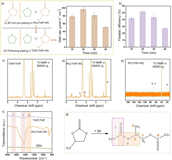
We also designed a “real lab, low purity effort” experiment in which the cathode plating was conducted in PC//THF+PC system for 20 min to form a tight SEI layer of suitable thickness, and then continued the plating process in the THF//THF+PC system for 10 to 40 min (Figure 3a). It is worth noting that all the solvents used in this set of experiments were acquired from commercial sources and were used without further treatment (Figure S22). Preparation of the electrolyte was performed in an open laboratory environment. A higher FE of 51.9±2.7 % and a yield rate of 96.9±5.0 μmol h−1 cm−2 on the stage of Li3N were obtained for 20 min/20 min plating (Figures 3a, b and S23, S24), compared to that when Li plating was conducted in one step in THF//THF+PC system (FE=15.4±3.2 %).
Figure 3.
a) Yield rates and b) Faradaic efficiencies of Li3N for the experiments conducted by electroplating lithium metal in the PC//THF+PC system for 20 min to form the SEI layer of a suitable thickness followed by electroplating in the THF//THF+PC system for various periods of time (all were conducted at a current density of −15 mA cm−2). Error bars denote the standard deviations of yield rates and the Faradaic efficiencies calculated from three independent experiments. c) 1H NMR spectrum of the SEI layer (removed from the electrode) after plating in the THF//THF system. d) 1H NMR and e) 13C NMR spectra of the SEI layer (removed from the electrode) after plating in the PC//THF+PC system. f) FTIR spectra for SSM electrodes after plating in the THF//THF and PC//THF+PC systems. g) The lithium 1,2‐propylene dicarbonate (main component of SEI) was synthesized from PC upon 2 e− reduction. The labels a, b and c in Figure 3d and 3e correspond to structural motifs illustrated in Figure 3g.
The organic component of the SEI primarily arises from the electrochemical reduction of PC as indicated by a weak reduction peak in the discharge curve at ≈−3.2 V versus Ag/Ag+ (Figure S14). The structure of PC‐derived products in the SEI was elucidated by the nuclear magnetic resonance (NMR) spectroscopy and Fourier‐transform infrared spectroscopy (FTIR) (Figures 3c–f and S25). [37] Thus, PC is reduced to lithium propylene dicarbonate (LPDC) via a two‐electron pathway (Figure 3g). Different from the results of FTIR acquired for the organic component of SEI in the solid state, the NMR spectrum of the sample dissolved in DMSO‐d 6 does not show a carbonate (O−C−O) moiety. After electrolysis in the THF//THF system the organic component of the SEI was hardly detectable at the electrode surface and was presumably dissolved in THF which explains why the plated lithium is more likely to react with dinitrogen in these systems.
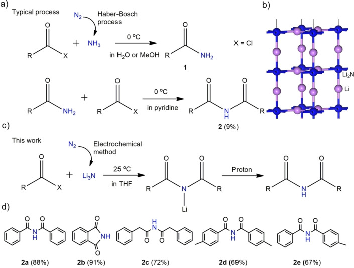
Having achieved maximal efficiencies of up to 85 % in the synthesis of Li3N, we turned our attention to the synthesis of aryl imides. Classically, this is synthesized via a two‐step process. For example, the first amidation reaction is conducted in H2O or methanol solution to synthesize benzamide 1 from benzoyl chloride and NH3; and then the second amidation reaction of the benzamide 1 by benzoyl chloride is continued in pyridine solvent to generate N‐benzoylbenzamide 2, however only with a yield of 9 % (Figures 4a and S26). [22] To reduce energy consumption and material losses in the synthesis of imides, we explored the possibility of a heterogeneous, direct coupling of two aroyl electrophiles and a R−Li2N nucleophile that exists as layer termination in the surface of the Li3N crystal deposited at the SSM (Figure 4b). Unlike the synthesis of imides from acid chlorides and ammonia, which requires an external base to bind the released HCl for shifting the equilibrium towards the product, reacting with Li3N the released chloride anions are bound in thermodynamically stable LiCl, which largely even precipitates from solution (Figure S27) and 95.4 % of the lithium can be recovered and looped into the Li3N synthesis again (Figure S28). Therefore, the method is sustainable and makes the two‐step amidation reaction simplified into one step (Figure 4c).
Figure 4.
a) A typical two‐step procedure of aryl imide synthesis that is based on the amidation reaction using fossil‐fuel‐derived NH3 produced at high temperature and high pressure. [7] b) Crystal structure of Li3N, showing Li2N layers perpendicular to the c axis. c) One‐step synthesis of aryl imides from Li3N produced by an electrochemical method under mild conditions. d) Calculated yield for the synthesis of various aryl imides.
To verify the feasibility of the arylimide synthesis, first we attempted to use a certain amount of commercially available Li3N by reacting it with acid chlorides (Supporting Information Note 1). In this case, symmetric aryl imides, such as N‐benzoylbenzamide 2 a, isoindoline‐1,3‐dione 2 b, 2‐phenyl‐N‐(2‐phenylacetyl)acetamide 2 c and 4‐methyl‐N‐(4‐methylbenzoyl)benzamide 2 d were synthesized with isolated yields of 88 %, 91 %, 72 % and 69 %, respectively (Figures 4d and S29–S37). Asymmetric N‐benzoyl‐4‐methylbenzamide 2 e was obtained with a FE of 67 % when benzoyl chloride and p‐toluoyl chloride were used in a 1 : 2 ratio (Figure S38). According to the amount of Li3N quantified by the indophenol blue method, an integrated current efficiency of 57–77 % and 35–47 % for the synthesis of aryl imides could be calculated for the cases of plated Li in an optimized, small‐scale battery system and a large electrolyzer cell for chemistry, respectively. This was experimentally verified when we switched to Li3N prepared by Li plating followed by nitridation as schematically shown in Figure 1b. For example, an integrated current efficiency of 73 % for the synthesis of N‐benzoylbenzamide 2 a was achieved by reacting a Li3N‐loaded electrode from a small‐scale battery with benzoyl chloride (Figure S39).
Unlike a previously reported method, according to which Li3N is dissolved in polar solvents and as such does not retain its crystal structure, [38] in our method the reaction proceeds at the converted electrode surface gradually consuming the Li3N crystals. The formation of aryl imides proceeds presumably via consecutive attack of two aromatic acid chlorides at the nucleophilic N atoms of the Li2N layer followed by displacement of three Li ions to form the lithium salt of aryl imides (Figure S40) and lithium chloride. Then aryl imides were formed as the solution‐containing lithium salt of aryl imides was quenched with diluted HCl during reaction mixture work up. Therefore, the Li3N crystal directs the synthesis of imides, but not of amides which obviously stay bound to the surface.
In conclusion, this work demonstrates that Li‐battery technology, used in a different context, allows the synthesis of rather complex compounds with high yields and practically no involvement of solvents and purification, thus making the whole process convenient and rather sustainable (see Supporting Information Note 2). At the first stage, a stainless‐steel mesh is electrochemically plated with Li metal, as occurs in many batteries, safely and repeatedly. Energy loss at this stage is mostly due to the initial Coulombic efficiency of a battery set‐up, which is to be controlled by formation of an appropriate SEI layer, either from standard mixed carbonate solvents or—for higher rates but lower efficiencies—a mixed electrolyte composed of THF and propylene carbonate. This lithium‐loaded electrode is then reacted in a second step with gaseous N2 to convert the Li metal into Li3N. In small standard electrochemical model cells, this reaction can be performed with electron‐to‐molecule yields of up to 85 %.
To generate a higher synthetic use of the energy content of Li3N, an otherwise uphill reaction was performed, and the direct synthesis of acylimides from acylchlorides was explored. Interestingly, this heterogeneous reaction (contrary to a more homogeneous analogue) immediately gives the imides not the amides, directly in the highest yields. We attribute this to the layered structure of Li3N where the terminating layer of Li2N moieties enables two C−N coupling events at one nucleophilic site. Therefore, the layered structure of Li2N serves as a template that directs formation of imides, but not amides. Successful validation and mechanistic understanding of this new combined method of electrochemical and chemical tandem reaction will allow developing other processes employing the higher nucleophilicity of Li3N in synthesis of value‐added nitrogen‐containing compounds from abundant N2 gas, helping to reach the zero emission goals for the chemical industry. On the metal side, it looks straightforward to generalize the presented approach also to Na, Mg, or Zn metalorganic synthons, using voltage as an additional driving force and SEI‐processes to avoid passivation.
Supporting Information: The Supporting Information includes additional discussion, full experimental details, and supplementary characterization data.
Conflict of interest
The authors declare no conflict of interest.
Supporting information
As a service to our authors and readers, this journal provides supporting information supplied by the authors. Such materials are peer reviewed and may be re‐organized for online delivery, but are not copy‐edited or typeset. Technical support issues arising from supporting information (other than missing files) should be addressed to the authors.
Supporting Information
Acknowledgements
G.F.C. thanks the Alexander von Humboldt Foundation for a postdoctoral fellowship. H.H. Wang thanks financially supported by National Key R&D Program of China (Grant No. 2020YFB1505603) and National Natural Science Foundation of China (No. 22138005). Open Access funding enabled and organized by Projekt DEAL.
G.-F. Chen, A. Savateev, Z. Song, H. Wu, Y. Markushyna, L. Zhang, H. Wang, M. Antonietti, Angew. Chem. Int. Ed. 2022, 61, e202203170; Angew. Chem. 2022, 134, e202203170.
Contributor Information
Dr. Gao‐Feng Chen, Email: gaofeng.chen@mpikg.mpg.de.
Prof. Haihui Wang, Email: cehhwang@tsinghua.edu.cn.
Prof. Markus Antonietti, Email: Markus.Antonietti@mpikg.mpg.de.
Data Availability Statement
The data that support the findings of this study are available from the corresponding author upon reasonable request.
References
- 1. Benjamin M. C., Porfirio F., Christian O. D., Yu-Hsuan L., Carlos A. F., Pratham A., Matthew R., Upendra S., Marta C. H., Andrew J. M., Joule 2019, 3, 1578–1605. [Google Scholar]
- 2. Suryanto B. H., Du H. L., Wang D., Chen J., Simonov A. N., MacFarlane D. R., Nat. Catal. 2019, 2, 290–296. [Google Scholar]
- 3. Chen J. G., Crooks R. M., Seefeldt L. C., Bren K. L., Bullock R. M., Darensbourg M. Y., Holland P. L., Hoffman B., Janik M. J., Jones A. K., Kanatzidis M. G., King P., Lancaster K. M., Lymar S. V., Pfromm P., Schneider W. F., Schrock R. R., Science 2018, 360, eaar6611. [DOI] [PMC free article] [PubMed] [Google Scholar]
- 4. Lai F., Zong W., He G., Xu Y., Huang H., Weng B., Rao D., Martens J. A., Hofkens J., Parkin I. P., Liu T., Angew. Chem. Int. Ed. 2020, 59, 13320–13327; [DOI] [PubMed] [Google Scholar]; Angew. Chem. 2020, 132, 13422–13429. [Google Scholar]
- 5. Tang C., Zheng Y., Jaroniec M., Qiao S. Z., Angew. Chem. Int. Ed. 2021, 60, 19572–19590; [DOI] [PubMed] [Google Scholar]; Angew. Chem. 2021, 133, 19724–19742. [Google Scholar]
- 6. Wang X., Jiao Y., Li L., Zheng Y., Qiao S. Z., Angew. Chem. Int. Ed. 2022, 61, e202114253; [DOI] [PubMed] [Google Scholar]; Angew. Chem. 2022, 134, e202114253. [DOI] [PubMed] [Google Scholar]
- 7. Soloveichik G., Nat. Catal. 2019, 2, 377–380. [Google Scholar]
- 8. Li L., Tang C., Jin H., Davey K., Qiao S. Z., Chem 2021, 7, 3232–3255. [Google Scholar]
- 9. Kim S., Loose F., Chirik P. J., Chem. Rev. 2020, 120, 5637–5681. [DOI] [PubMed] [Google Scholar]
- 10. Lv Z. J., Wei J., Zhang W. X., Chen P., Deng D., Shi Z. J., Xi Z., Nat. Sci. Rev. 2020, 7, 1564–1583. [DOI] [PMC free article] [PubMed] [Google Scholar]
- 11. Chen C., Zhu X., Wen X., Zhou Y., Zhou L., Li H., Tao L., Li Q., Du S., Liu T., Yan D., Xie C., Zou Y., Wang Y., Chen R., Huo J., Li Y., Cheng J., Su H., Zhao X., Cheng W., Liu Q., Lin H., Luo J., Chen J., Dong M., Cheng K., Li C., Wang S., Nat. Chem. 2020, 12, 717–724. [DOI] [PubMed] [Google Scholar]
- 12. Zhao X., Hu G., Chen G. F., Zhang H., Zhang S., Wang H., Adv. Mater. 2021, 33, 2007650. [DOI] [PubMed] [Google Scholar]
- 13. Chen G. F., Yuan Y., Jiang H., Ren S. Y., Ding L. X., Ma L., Wu T., Lu J., Wang H., Nat. Energy 2020, 5, 605–613. [Google Scholar]
- 14. Tang C., Qiao S. Z., Chem. Soc. Rev. 2019, 48, 3166–3180. [DOI] [PubMed] [Google Scholar]
- 15. Foster S. L., Bakovic S. I. P., Duda R. D., Maheshwari S., Milton R. D., Minteer S. D., Janik M. J., Renner J. N., Greenlee L. F., Nat. Catal. 2018, 1, 490–500. [Google Scholar]
- 16. Suryanto B. H., Matuszek K., Choi J., Hodgetts R. Y., Du H. L., Bakker J. M., Kang C. S. M., Cherepanov P. V., Simonov A. N., MacFarlane D. R., Science 2021, 372, 1187–1191. [DOI] [PubMed] [Google Scholar]
- 17. Park K., Yu B. C., Goodenough J. B., Adv. Energy Mater. 2016, 6, 1502534. [Google Scholar]
- 18. Wang K., Deng Z. H., Xie S. J., Zhai D. D., Fang H. Y., Shi Z. J., Nat. Commun. 2021, 12, 248. [DOI] [PMC free article] [PubMed] [Google Scholar]
- 19. Bhosale S. V., Jani C. H., Langford S. J., Chem. Soc. Rev. 2008, 37, 331–342. [DOI] [PubMed] [Google Scholar]
- 20. Kim E. S., Park K. Y., Heo J. M., Kim B. J., Ahn K. D., Lee J. G., Ind. Eng. Chem. Res. 2010, 49, 11250–11253. [Google Scholar]
- 21. Savoia D., Concialini V., Roffia S., Tarsi L., J. Org. Chem. 1991, 56, 1822–1827. [Google Scholar]
- 22. Trowbridge A., Reich D., Gaunt M. J., Nature 2018, 561, 522–527. [DOI] [PubMed] [Google Scholar]
- 23. Reddy P. Y., J. Org. Chem. 1997, 62, 2652–2654. [DOI] [PubMed] [Google Scholar]
- 24. Yang C., Adv. Mater. Res. 2012, 550, 2733–2737. [Google Scholar]
- 25. Ma J. L., Bao D., Shi M. M., Yan J. M., Zhang X. B., Chem 2017, 2, 525–532. [Google Scholar]
- 26. Zhang X., Han A., Yang Y., J. Mater. Chem. A 2020, 8, 22455–22466. [Google Scholar]
- 27. Kim K., Chen Y., Han J.-I., Yoon H. C., Li W., Green Chem. 2019, 21, 3839–3845. [Google Scholar]
- 28. Lazouski N., Chung M., Williams K., Gala M. L., Manthiram K., Nat. Catal. 2020, 3, 463–469. [Google Scholar]
- 29. Kim K., Lee S. J., Kim D. Y., Yoo C. Y., Choi J. W., Kim J. N., Woo Y., Yoon H. C., Han J. I., ChemSusChem 2018, 11, 120–124. [DOI] [PubMed] [Google Scholar]
- 30. Andersen S. Z., Čolić V., Yang S., Schwalbe J. A., Nielander A. C., McEnaney J. M., Enemark-Rasmussen K., Baker J. G., Singh A. R., Rohr B. A., Statt M. J., Blair S. J., Mezzavilla S., Kibsgaard J., Vesborg P. C. K., Cargnello M., Bent S. F., Jaramillo T. F., Stephens I. E. L., Nørskov J. K., Chorkendorff I., Nature 2019, 570, 504–508. [DOI] [PubMed] [Google Scholar]
- 31. Tsuneto A., Kudo A., Sakata T., J. Electroanal. Chem. 1994, 367, 183–188. [Google Scholar]
- 32. Lazouski N., Schiffer Z. J., Williams K., Manthiram K., Joule 2019, 3, 1127–1139. [Google Scholar]
- 33. Kim K., Cho H., Jeon S. H., Lee S. J., Yoo C. Y., Kim J. N., Choi J. W., Yoon H. C., Han J. I., J. Electrochem. Soc. 2018, 165, F1027–F1031. [Google Scholar]
- 34. Hu Y. S., Demir-Cakan R., Titirici M. M., Müller J. O., Schlögl R., Antonietti M., Maier J., Angew. Chem. Int. Ed. 2008, 47, 1645–1649; [DOI] [PubMed] [Google Scholar]; Angew. Chem. 2008, 120, 1669–1673. [Google Scholar]
- 35. Suo L., Oh D., Lin Y., Zhuo Z., Borodin O., Gao T., Wang F., Kushima A., Wang Z., Qi H.-C., Kim Y., Yang W., Pan F., Li J., Xu K., Wang C., J. Am. Chem. Soc. 2017, 139, 18670–18680. [DOI] [PubMed] [Google Scholar]
- 36. Kanamura K., Tamura H., Takehara Z. I., J. Electroanal. Chem. 1992, 333, 127–142. [Google Scholar]
- 37. Xu K., Zhuang G. V., Allen J. L., Lee U., Zhang S. S., P. N. Ross Jr , Jow T. R., J. Phys. Chem. B 2006, 110, 7708–7719. [DOI] [PubMed] [Google Scholar]
- 38. Baldwin F. P., Blanchard E. J., Koenig P. E., J. Org. Chem. 1965, 30, 671–673. [Google Scholar]
Associated Data
This section collects any data citations, data availability statements, or supplementary materials included in this article.
Supplementary Materials
As a service to our authors and readers, this journal provides supporting information supplied by the authors. Such materials are peer reviewed and may be re‐organized for online delivery, but are not copy‐edited or typeset. Technical support issues arising from supporting information (other than missing files) should be addressed to the authors.
Supporting Information
Data Availability Statement
The data that support the findings of this study are available from the corresponding author upon reasonable request.


