Abstract
Background
Accurate needle placement into soft tissue is essential to percutaneous prostate cancer diagnosis and treatment procedures.
Methods
This paper discusses the steering of a 20 gauge (G) FBG-integrated needle with three sets of Fiber Bragg Grating (FBG) sensors. A fourth-order polynomial shape reconstruction method is introduced and compared with previous approaches. To control the needle, a bicycle model based navigation method is developed to provide visual guidance lines for clinicians. A real-time model updating method is proposed for needle steering inside inhomogeneous tissue. A series of experiments were performed to evaluate the proposed needle shape reconstruction, visual guidance and real-time model updating methods.
Results
Targeting experiments were performed in soft plastic phantoms and in vitro tissues with insertion depths ranging between 90 and 120 mm. Average targeting errors calculated based upon the acquired camera images were 0.40 ± 0.35 mm in homogeneous plastic phantoms, 0.61 ± 0.45 mm in multilayer plastic phantoms and 0.69 ± 0.25 mm in ex vivo tissue.
Conclusions
Results endorse the feasibility and accuracy of the needle shape reconstruction and visual guidance methods developed in this work. The approach implemented for the multilayer phantom study could facilitate accurate needle placement efforts in real inhomogeneous tissues.
Keywords: needle steering, FBG sensor, prostate intervention, multilayer phantom insertion
Introduction
Prostate cancer is the second most common cancer in men and a leading cause of cancer death in the United States, according to an American Cancer Society report in 2014 (1). The mainstream clinical procedures for diagnosing and treating prostate cancer include percutaneous prostate interventions, among which the clinician inserts a surgical needle to a target region inside the prostate either to take a tissue sample for diagnosis (biopsy), and to place radioactive seeds for treatment (brachytherapy). Recent studies have focused on the application of steering a flexible bevel-tip needle to avoid obstacles such as vital blood vessels and other anatomic structures (2,3). Webster et al. (4) proposed a nonholonomic model to describe the needle behavior during insertion. Abayazid et al. (5) used an ultrasound-guided insertion device to perform 3D needle steering in biological tissue based on a previously developed trajectory planning method (6).
For the sake of targeting accuracy and patient safety, it is important to keep track of the needle position during percutaneous interventions. This can be done via several different imaging modalities. Ultrasound (US) is a widely used, low-cost, gold standard navigation method for biopsy (7) and has been used in numerous needle placement studies (5,8). However, US imaging provides poor soft tissue contrast in prostate; and therefore the tumor is hardly visible. In addition, the acquired images can be significantly distorted by the US probe (3). Computed tomography (CT) provides high-quality images (9), but using CT throughout the percutaneous interventions exposes both the patient and the clinician to a large dose of X-ray radiation. In contrast to US and CT, magnetic resonance imaging (MRI) is an ideal imaging modality for prostate interventions (10–12) because it can provide the best soft tissue contrast among the three imaging modalities and tumors can be clearly spotted in MR images (13). However, due to the strong magnetic and radio frequency field of an MR scanner, the tools used inside or near the scanner have to be made of only non-ferromagnetic materials, which is not possible with most of the standard clinical instruments. This has led to significant research efforts to develop MRI-compatible robotic devices in the aspect of actuation methods, including pneumatic actuators (14,15), piezomotors (16,17) and ultrasonic motors (18–20).
In terms of imaging frequency, the time delay between MRI frames limits its capability of tracking the needle trajectories in real time. Therefore, there is a critical unmet need for tracking the needle fast and accurately. Studies have shown the potential of enhancing flexible needles with embedded Fiber Bragg Grating (FBG) sensors to estimate needle shapes. This approach aims to alleviate the need for real-time high-resolution images to track the needle during insertion. Optical fibers with a small diameter are etched with gratings that have specific reflection wavelengths, and are attached along the needle shaft. The data from the FBG sensors are acquired by an interrogator with a high frequency up to 20 kHz, which allows real-time shape reconstruction. The needle is fabricated using only non-ferromagnetic materials, and thus it is MRI-compatible. Park et al. (21) designed an 18 G needle with two sets of FBG sensors. Free-space single-bend experiments demonstrated the feasibility to utilize FBG sensors for shape sensing. Roesthuis et al. (22) attached fibers with four sets of FBG sensors on a 1 mm diameter nitinol wire. They proposed a piecewise interpolation method for needle shape reconstruction, and it was later combined with an automatic 3D steering algorithm in (23). The in-plane double-bend targeting error was 2.0 mm. In (24) they used a similar method to steer a 2 mm diameter active-tip needle and achieved a targeting error below 2.02 mm.
In previous studies, we developed a series of MRI-compatible prostate needle placement systems, initially actuated by pneumatic cylinders (25) and then improved by utilizing non-magnetic ultrasonic motors (26,27). These 4-degrees-of-freedom (DOF) robotic systems can assist clinicians to place an off-the-shelf surgical needle precisely during manual biopsy or brachytherapy procedures. Our latest prototype (27) has been approved by the Institutional Review Board (IRB) and is currently under clinical testing. The use of this system can further be extended to teleoperated needle steering applications by adding an ultrasonic motor-driven needle driver module (28) and by using a FBG-integrated smart needle, which was developed in our earlier work using FBG sensors with a preliminary shape reconstruction method (29).
This study builds on our earlier work with the following main contributions: (1) a comparison among various needle shape reconstruction approaches and a novel fourth-order polynomial-based shape reconstruction method; (2) a computer-assisted navigation system based on FBG shape sensing and trajectory prediction model to assist targeting; and (3) a real-time model updating approach based on tissue property estimation for precise needle steering inside inhomogeneous tissues. The experimental results verified the feasibility and accuracy of the proposed shape sensing based needle steering approach. The ultimate goal of this study is to use the real-time reconstructed needle shape from the FBG sensors to assist clinicians to perform accurate and safe needle insertions via an in-bore MRI-compatible robot.
Materials and methods
Design of the FBG-integrated needle
The aim of this part is to develop a bevel tip needle that is able to sense its own shape while it is being inserted and steered inside soft tissue. To this end, we adapted a standard 20G (Φ = 0.9 mm) MRI-compatible bevel-tip brachytherapy needle (E-Z-EM Incorporation, NY, US, tip angle 30°). We embedded three optical fibers (Φ = 80 μm) around the inner stylet (Φ = 0.6 mm) of the needle with an angle of 120° between each other. Each fiber has three FBG sensors located at 11, 26 and 70 mm from the needle tip. Figure 1 illustrates the assembly of the FBG-integrated needle. For transperineal prostate biopsy and brachytherapy, considering the typical location of prostate (40–70 mm deep from the perineum (30)), we determined our needle length and sensor loci based on a maximum insertion depth of 110 mm. During insertion, the small diameter of the needle is able to provide a larger bending range and thus better steering ability. This is, to the best of our knowledge, the thinnest FBG-integrated bevel-tip needle used in similar studies.
Figure 1.
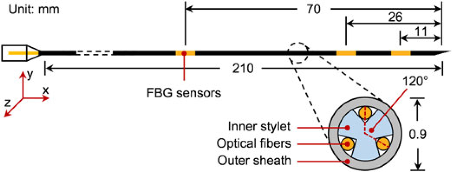
Configuration of the FBG-integrated needle. Optical fibers are attached on the needle’s inner stylet, which has been fabricated with three grooves at 120° to each other. The FBG sensors are located at positions 11, 26 and 70 mm from the needle tip
Needle shape reconstruction methods
According to (19), each FBG sensor reflects a specific wavelength of light (λB) which can be calculated by
| (1) |
where ne is the effective refractive index of the fiber core and Λ is the period of the grating. λ can be measured directly using an optical interrogator. In (30), local strain (ε) on the sensor and change of temperature (ΔT) will linearly shift the wavelength by
| (2) |
where kε and kΔT are constant coefficients associated with strain and temperature, respectively. If the temperature were constant during needle operation, two optical sensors would have been sufficient for 3D needle shape reconstruction. Using a third fiber enables temperature compensation and identifying the wavelength shift related to the strain alone. The approach is to compute the average wavelength shift of the three sensors at the same longitudinal location, and subtract this common mode from each of the Δλ values (29). Each of the remaining wavelength shifts after this step (Δλε) are linearly proportional to the local strain on each sensor (ε) at that location. Considering the two planes that are perpendicular to the needle axis and define the shape of the needle, assuming negligible twisting (xy and xz planes), there exist two proportionality constants for each sensor (cxy and cxz). These coefficients can be combined into a coefficient matrix (Cmat) to relate the total strain (ΔE) to optical wavelength shift of all sensors (ΔΛ). Therefore, for each sensor location (xi) we will have
| (3) |
where i = {1, 2, 3} denotes the 3 sensor locations along the needle. The coefficient matrix is obtained through experimental calibrations by applying a concentrated force at the needle tip on both xy and xz planes, using a similar method to that in (29).
Therefore, with the calibration matrix, the strain on the needle can be calculated by
| (4) |
where Cmat+ is the Moore–Penrose pseudo-inverse of Cmat.
For needle tip deflection less than 10% of the full length, the needle can be modeled as a Euler–Bernoulli beam. For a rod beam we have
| (5) |
where k(x) is the beam curvature at location x, and r is the radius of the transverse section. For the proposed needle design, r represents the distance from the fiber axis to the needle’s central axis. For the xy plane, with small deflection we can assume that y″(x) = k(x), where y(x) is the shape of the needle. Therefore, we have:
| (6) |
Equations in the xz plane are similar.
According to beam theory, the curvature at the needle tip can be assumed to be zero. Using the FBG wavelength shifts, the local curvature information at the three sensor loci can be obtained, and thus the needle shape can be reconstructed by various approaches. This section depicts the theory and computational steps of each method.
Method 1
In (29), Seifabadi et al. describe the curvature equation 6 as
| (7) |
where the coefficients A, B, C and D are obtained by fitting the curvature values at four locations (3 at sensing regions and 1 at the needle tip) to a third-order polynomial. Thus the needle shape y(x) can be calculated by integrating equation 7 twice. Taking the boundary conditions y′(0) = 0 and y(0) = 0 obtains
| (8) |
In this method, the needle shape is described by a fifthorder polynomial. Generally, the bigger the number of sensing regions on the needle, the higher the order of the profile function. This method relies strictly on the accurate curvature values, because a small discrepancy at any sensor location may lead to a significant change in the equation 7, and thus the needle shape.
Method 2
Roesthuis et al. (22) assume that the needle has a continuous curvature. The curvature along the longitudinal axis can be obtained by linking the acquired curvature values at each sensor location. The needle shape is modeled as a connection of pieces of smaller discrete curves. The curvature plot (same shape as strain plot) for this method is identical to the situation where concentrated forces are applied only at the sensor loci. This approach has high robustness, as any inaccuracy in readings from the sensors close to the needle tip does not influence the profile segment that has already been reconstructed from the sensor readings near the needle base. However, this method is less suitable when stresses are not concentrated at the sensor loci.
Method 3
From the analysis in (31), when the needle is inserted into soft tissue, the lateral force along the needle axis is more of a distributed load rather than a concentrated point load. Therefore, in this case, we can assume that the needle will take a shape described by a fourth-order polynomial function. This reconstruction approach is a trade-off between method 1 and 2, and thus it is a balance between accuracy and sensitivity. The needle shape in this method is given by the following equation:
| (9) |
As shown in Figure 2, the first steps in each method are the same. Signals from the FBG sensors are converted into wavelength shifts, and strain values at the sensor loci are calculated by applying the calibration matrix Cmat. The curvatures at these loci are then obtained using equation 5. The three reconstruction methods differ mainly in terms of the interpolation of sampled curvatures. The difference of interpolation approaches leads to discrepancies on the shapes of the curvatures, and finally results in different needle shapes after integration of the curvatures.
Figure 2.
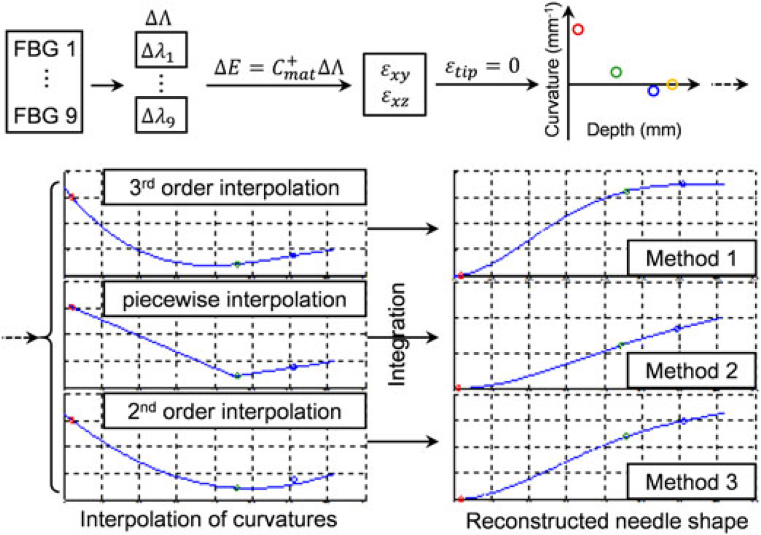
Needle shape reconstruction procedure. First, curvatures at sensor loci are calculated from FBG wavelength readings. Then, different interpolation methods are applied and the needle shape is achieved by integrating the curvature equation twice
Experiment 1: comparison of needle shape reconstruction methods.
Phantom study was performed to compare and evaluate the aforementioned three reconstruction methods in 2D. The experimental setup is illustrated in Figure 3. A Cartesian stage is used to drive the needle. The soft-tissue phantom, made from liquid plastic (M-F Manufacturing Company, TX, USA), is contained in a transparent box with six parallel entry holes 10 mm apart on the side. A calibrated CCD camera (FL208S2C, Point Grey, BC, Canada, resolution 1024 × 768) is used to capture the needle profile as the ground truth. It is fixed above the phantom box at a proper height to cover the entire phantom region, and the resolution in the obtained image is 0.24 mm per pixel. A light panel is placed underneath the phantom box to enhance contrast of the needle in the image. The needle shape is reconstructed in real time with respect to the insertion depth.
Figure 3.
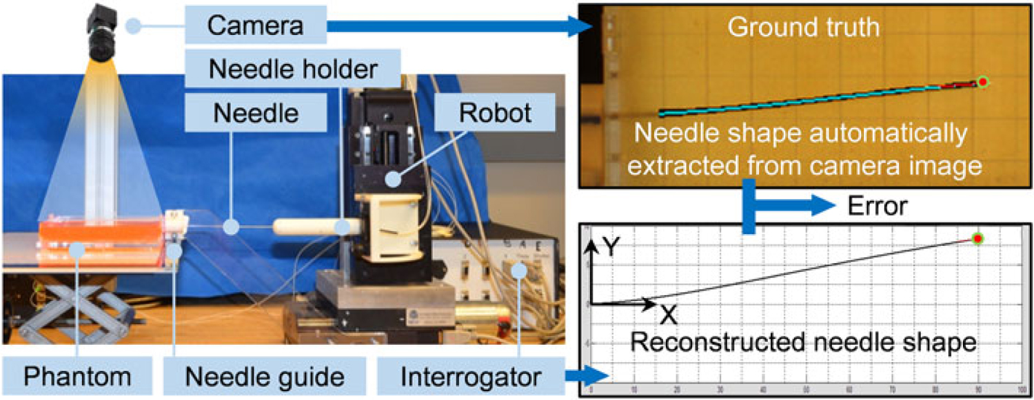
The experimental setup and information flow. A series of image processing steps are undergone in order to automatically fit the sampling points of the needle into a polynomial line as the ground truth of the needle shape. In the top right figure, the extracted needle shape (cyan) is overlaid onto the original needle (black) in the image. The error is defined as the difference between ground and the shape reconstructed from FBG measurements
Using this setup, single bend experiments (Experiment 1.1) were carried out first to examine the three reconstruction methods. The needle was inserted in steps of 5 mm, with no axial rotations, to reach a depth of 90 mm. The actual (from the CCD camera image) and computed (from shape reconstruction based on FBG measurements) needle tip positions were recorded at each step. The absolute error is defined as the distance in the y direction (perpendicular to the insertion direction, Figure 3) between the two needle tip positions, since in our cases the change of the needle along the x axis (along needle insertion direction, Figure 4) is neglectable and could be adjusted by insertion. Second, double-bend insertion trials (Experiment 1.2) were conducted. The needle was rotated at depths varying from 35 to 70 mm in order to cover most of the possible rotation points for a total insertion depth of 90 mm. Ten consecutive trials are carried out for both single bend and double bend insertions.
Figure 4.

Defined by the two guidance lines starting from the needle tip, the reachable region shows the maximum range of needle motion. The initial slope and the slope shift are caused by the needle’s bevel tip cut angle
Model-based computer-assisted navigation system
The ultimate goal of this study is to use the reconstructed needle shape from the FBG sensors to assist clinicians to perform accurate needle insertion via visual feedback. Due to the asymmetric force on the needle’s bevel tip, the needle naturally bends and deflects out of the initial insertion direction during the process. Therefore, it is important to determine appropriate steering points to rotate the needle, and thus to adjust the bending direction and guide the needle towards the clinical target accurately. If the needle deflection can be predicted accurately, the visual feedback can be enhanced by overlaying trajectory predictions and suggesting appropriate steering loci to the clinician. Hence, hopefully, it can offer significantly better targeting accuracy and much easier operation than conventional bare hand operation exerted by clinicians.
Retracting and reinserting the needle or rotating it frequently to adjust the bending direction (for instance, continuously spinning the needle or duty cycling to vary the trajectory curvature (32)) will introduce additional trauma to the tissue (33). For this reason, it is important to identify the insertion path that requires the minimum number of rotations. We propose a model-based real-time navigation algorithm in order to help clinicians find such paths and to visually guide them to stay on the path throughout operations.
In (4), the bevel tip needle is modeled as a nonholonomic bicycle which generates an arc with constant curvature while inserting inside soft phantoms. Based on the bicycle model, the path changes its direction when the needle rotates 180°, and the trajectory is comparable with the situation that a moving bicycle turns to another direction. If the turning angle is known and the tissue is homogenous, the path of the needle tip is predictable. The guidance is designed by introducing two guidance lines, which are generated based on the bicycle model, emitting from the reconstructed needle tip. As shown in Figure 4, one of the lines shows the needle path in the current direction, while the other one is the predicted needle path when the needle is rotated at the current point. The two guidance lines enclose an area called the reachable region. The needle tip can arrive at any point inside this region with proper steering, but the region outside the area is not achievable. The principle of needle guidance is as follows. At the beginning, the needle direction is set to incorporate the target in the reachable region. While the needle is inserting, the reachable region decreases until the guidance line passes through the target (i.e. intersects with a guidance line, Figure 4). At this moment, the needle should be rotated axially to change the bending direction towards the target.
Two parameters are required for generating the guidance lines: the initial slope (θi) and the radius of the needle tip trajectory (Rbicycle). The initial slope is the angle between the tangent line of the needle tip trajectory through the entry point and the normal line perpendicular to the surface. The radius of the needle trajectory is calculated by fitting the single bend needle shape into a circle via least squares. These parameters can be acquired experimentally from single bend insertions, as described in Experiment 1.1. Based on the bicycle model, the angle shift (Figure 4), which represents the change of direction when the needle is rotated, is obtained by doubling the initial slope.
Experiment 2: insertion trials under computer-assisted navigation.
Needle insertion experiments are performed to evaluate the proposed navigation method using homogenous phantoms. This experiment is a proof-of-concept test for the proposed computer-assisted needle steering approaches. Nine different targets are set inside an isotropic soft tissue phantom, and the experimental setup is shown in Figure 5. During the experiment, the operator inserts the needle by taking discrete steps of 5 mm at the beginning and 1 mm when approaching the target region.
Figure 5.
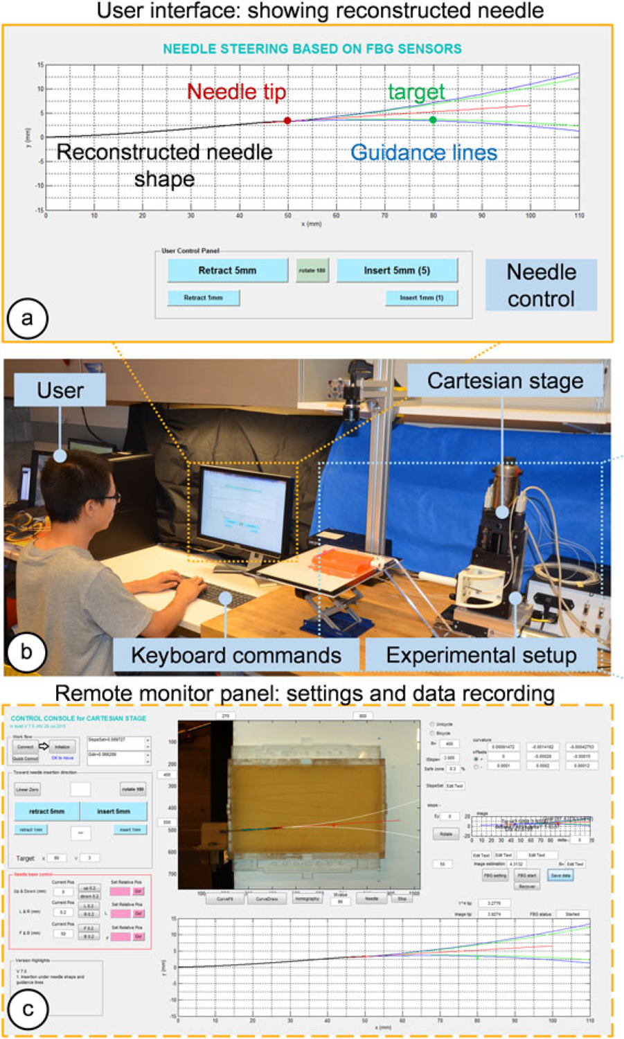
The experiment setup for insertion trials under computer-assisted navigation. The operator controls the Cartesian stage to steer the needle via an MRI-compatible keyboard under visual guidance. (a) Guidance lines are generated from FBG-based reconstructed needle shape. (b) A scene during the experiment. (c) A remote monitor panel functions as a control console to set up parameters and record data. In this phantom insertion study, needle shapes extracted from camera images are used as ground truths
During the trials, only insertions and one rotation of 180° were allowed, with no retraction/reinsertion. The motions were exerted automatically by clicking corresponding keys on the keyboard. The rotation point was instructed through visual guidance on the graphical user interface (GUI), on which the reconstructed needle shape, target and predicted insertion trajectory were shown and updated in real time. The operator inserts the needle gradually, and the guidance line will move forward with the needle tip position. At one point, the guidance line will intersect with the target point, and this is the time the operator is required to rotate the needle. To avoid the case that the target goes out of the needle’s achievable region because of needle overshoot caused by the operator’s subjectivity, we added a safe zone of 3% (Rsafe = 103 % × Rguidance) to the boundary lines as auxiliary guidance for the operator. In this way, the possible bias is confined to a small region between the guidance line and the safety line, which guarantees the conformance of the operator’s performance. The initial slope (θi) and radius of the guidance line (Rbicycle) are obtained from the previous phantom insertion study as θi = 4.3° and Rbicycle = 400 mm.
Four operators were asked to perform the experiment. The operators were kept in the control loop for in clinical circumstances it is necessary to have a clinician in loop for target selection and safety reasons. As in Experiment 1, the CCD camera is used to capture the needle profile as the ground truth and to calculate targeting errors.
Real-time model updating with tissue property estimation in inhomogeneous tissue
As mentioned previously, the guidance algorithm includes two important parameters: the initial slope and the radius of guidance lines. In homogeneous tissue, these parameters can be obtained from a single-bend insertion experiment and applied in further studies. However, in practice, soft tissue in a human body is not likely to be homogeneous, and thus it is essential to find a method that is able to estimate tissue–needle properties and acquire the parameters for different tissue layers. Furthermore, this makes it possible to predict and update the needle trajectory on the fly during insertion without requiring any pre-operative characterization of the tissue.
The needle in our design has an FBG sensor very close (11 mm) to the needle tip. We use the FBG information to compute a curvature value at this sensor location. According to the bicycle model, the curvature should keep a constant value throughout insertion in an isotropic, homogeneous tissue. However, for tissues with varying stiffness, the radius of curvature will change. By continuously tracking the tip-most FBG sensor readings, our needle can detect the change in tissue properties as soon as the needle enters a stiffer/softer medium.
The goal of needle insertions is to achieve accurate targeting results, and in our case, it relies on precisely estimating the guidance lines. For single-bend insertions, the guidance lines represent the radius of the needle tip trajectory, which in fact depends upon the tissue stiffness. Based on this dependence, we are able to find the mapping between the tip sensor readings and the guidance line radii. Therefore, as shown in Figure 6, for a tissue with unknown stiffness, it is possible to estimate the needle bending behavior by simply analyzing the reading of the tip FBG sensor. If the tissue is not homogeneous during needle insertion, the needle could sense the change and thereby update the estimation.
Figure 6.
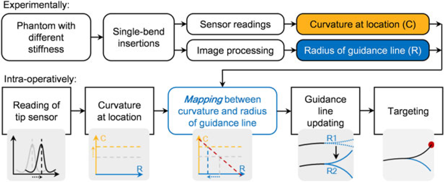
Work principle of the needle-tissue property estimation. First, the mapping between the sensor location curvature and the radius of guidance lines is obtained experimentally. Then during needle insertion into tissue with unknown stiffness, the guidance lines are updated by using the curvature information at the sensor location
Experiment 3.1: proof of assumption.
Several experiments were carried out to examine the proposed approach. In order to prove the assumption that the sensor is able to capture the change of tissue hardness, we performed insertions into a 2-layer phantom. The first half of the phantom (to 50 mm insertion depth) was made of soft plastic while the second half of the phantom was made of much harder plastic. The needle was inserted in discrete steps of 5 mm and the curvature value obtained from the tip FBG sensor was recorded at the end of each step. We expect the curvature to stay at one value before the needle reaches the second layer and change to another value afterwards.
Experiment 3.2: parameters mapping.
The next step in this study is to find the mapping between the curvatures measured at the tip sensor location versus the corresponding radius and initial slopes of the guidance lines, which are the two parameters that characterize the needle-to-tissue interaction. These parameters are obtained by performing single-bend insertions into several homogenous phantoms with different stiffness.
Five phantoms were made by mixing different ratios of liquid plastic materials as listed in Table 1. The abbreviated notation for each phantom type in Table 1 is used in the rest of this paper. SS represents the softest phantom, while HH is the stiffest with approximately the same hardness as a 30 OO Shore Hardness rubber sample. Five single-bend insertions were performed in each phantom to obtain the curvatures and radii of the guidance lines.
Table 1.
Phantom characteristics
| Phantom | Notation | Ingredient | |
|---|---|---|---|
| 1 | Soft | SS | Super soft plastic, 3:1 Softener |
| 2 | ↓ | S | Super soft plastic |
| 3 | ↓ | R | Regular plastic |
| 4 | ↓ | H | Regular plastic, 4:1 Hardener |
| 5 | Hard | HH | Regular plastic, 2:1 Hardener |
Experiment 3.3: targeting experiments.
Targeting experiments in this section incorporates four two-layer phantoms with different hardness combinations (SS–H, S–HH, SS–R and R–HH) as shown in Figure 7(a). In each phantom, six targets are randomly chosen at insertion depths of 80, 90 and 100 mm. All trials were performed with a single user who has no prior clinical experience. The experimental protocol is identical to that presented in Experiment 2.
Figure 7.
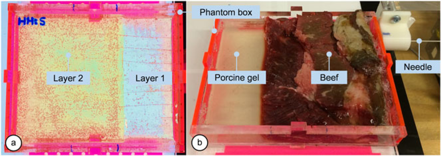
Multilayer phantoms. (a) A two-layer plastic phantom is made of a combination of plastics with different stiffness. (b) The bio-tissue is made with beef and transparent porcine gelatin
Experiment 3.4: in vitro insertions.
We extended our multilayer needle insertion study by testing the system on a nonhomogeneous bio-tissue phantom. As shown in Figure 7(b), the phantom box was partially filled with beef tissue while the rest was filled with transparent porcine gelatin so that the camera can capture the needle tip position at the end of each insertion. Six target points were selected at 100 mm insertion depth, and five insertions were performed per target.
Results
Comparison of needle shape reconstruction methods
Before the experiments, the calibration matrix (Cmat) in equation 3 for our newly built FBG-integrated needle is obtained as:
| (13) |
Single bend insertion trials
In the single bend insertion experiments, the mean absolute errors in estimated tip position show no significant difference among the three reconstruction methods, as shown in Figure 8(a). Thus, the three reconstruction methods perform similarly for the single-bend scenario, when using our FBG-integrated needle.
Figure 8.
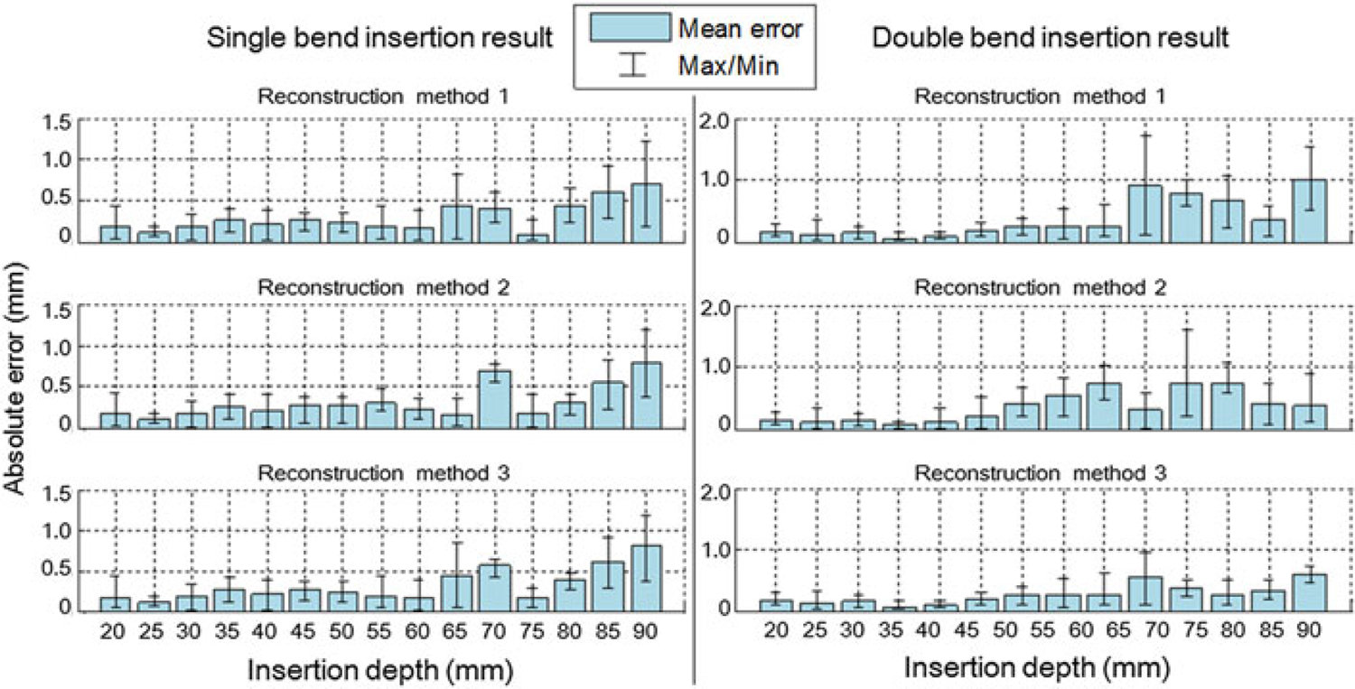
Error analysis of the single-bend and double-bend insertion experiments. Needle tip positions captured by the camera image are used as ground truth. (a) The three reconstruction methods show no obvious difference in absolute errors. At the insertion depth around 70 mm, the errors appear to be larger than average, because this area is the deepest position with only two sensors activated inside the phantom. At 75 mm, errors are decreased because the third sensor is activated, introducing one more curvature information. The mean errors are all below 1 mm throughout the whole depth. (b) The fourth-order reconstruction method (method 3) provides the best fit among the three methods. Average errors are mostly below 0.5 mm and maximum error is below 1 mm, compared with maximum average error of 1 mm and maximum error of 1.8 mm for the other two methods.
Double bend insertion trials
Figure 8(b) shows the error analysis of the double-bend insertion trials. Obviously, in this scenario the three methods demonstrate different results. The third method, i.e. the fourth-order polynomial shape reconstruction, has the least error. It is considered that the method has an accurate and stable output. Therefore, we choose this method for needle shape reconstruction in the following experiments.
Needle insertion experiments with homogenous phantoms
This section shows the result of needle insertion experiments utilizing the model-based human-in-loop navigation approach. The result of this experiment using the Cartesian stage is shown in Figure 9. The maximum targeting error for all 36 trials is 1.17 mm based on the acquired camera images and 1.50 mm according to the reconstructed needle shape. The mean targeting error and the standard deviation (SD) found by camera image and shape reconstruction are errimg = 0.40 ± 0.35 mm and errrec = 0.67 ± 0.49 mm, respectively.
Figure 9.
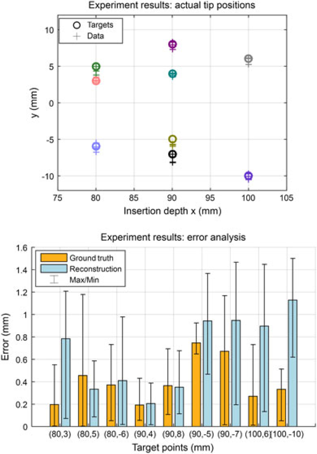
Results of insertion trials under computer-assisted navigation. (a) This figure shows the nine targets located at 80–100 mm depths for each operator, and the distribution of the final needle tip position captured by the camera. Different colors illustrate different targets. (b) The absolute tip positioning errors in camera images (ground truth) and reconstructions. The maximum errors are 1.17 mm and 1.50 mm, respectively. The overall errors are 0.40 ± 0.35 mm and 0.67 ± 0.49 mm. The results prove the effectiveness of the guidance algorithm
Needle insertion experiments using inhomogeneous phantoms
Proof of assumption
The needle is inserted with no rotation into a two-layer phantom. The observed sensor behavior is illustrated in Figure 10. Accordingly, the curvature computed from the FBG sensor remains steady until reaching the boundary between the two layers of the phantom. The curvature increases rapidly upon transition into the stiffer zone and then stabilizes at a constant value. This proves that the tip-most FBG sensor of the needle can effectively detect changes of stiffness during insertion into a multi-layer medium.
Figure 10.
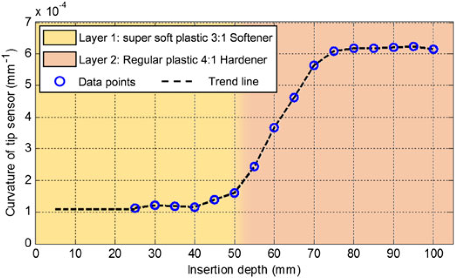
Tip sensor behavior during insertion into a 2-layer phantom
Parameters mapping
This experiment is to find the mapping between the curvatures measured at the tip sensor location versus the corresponding radius and initial slopes of the guidance lines. Five single-bend insertions in each phantom were performed, and the results are summarized in Table 2.
Table 2.
Mapping of curvature and radius
| PhantomNotation | Curvature at the tip sensor location (10−4 mm−1) | Radius of guidance lines (mm) | |
|---|---|---|---|
| 1 | SS | 1.32 ± 0.21 | 1111 ± 26 |
| 2 | S | 2.74 ± 0.51 | 570 ± 15 |
| 3 | R | 5.59 ± 0.72 | 463 ± 7 |
| 4 | H | 6.90 ± 0.70 | 379 ± 11 |
| 5 | HH | 8.15 ± 0.86 | 342 ± 10 |
Using the values in Table 2, the mapping between the curvature and radius values can be obtained. As shown in Figure 11, the curvatures in different phantoms are significantly different. The hardness of the tissue in a realistic needle insertion scenario may not exactly match one of the tested phantoms. In this case, we do linear interpolation between the mean values of the closest phantoms to find the radius of guidance lines which is updated in real time during insertion.
Figure 11.
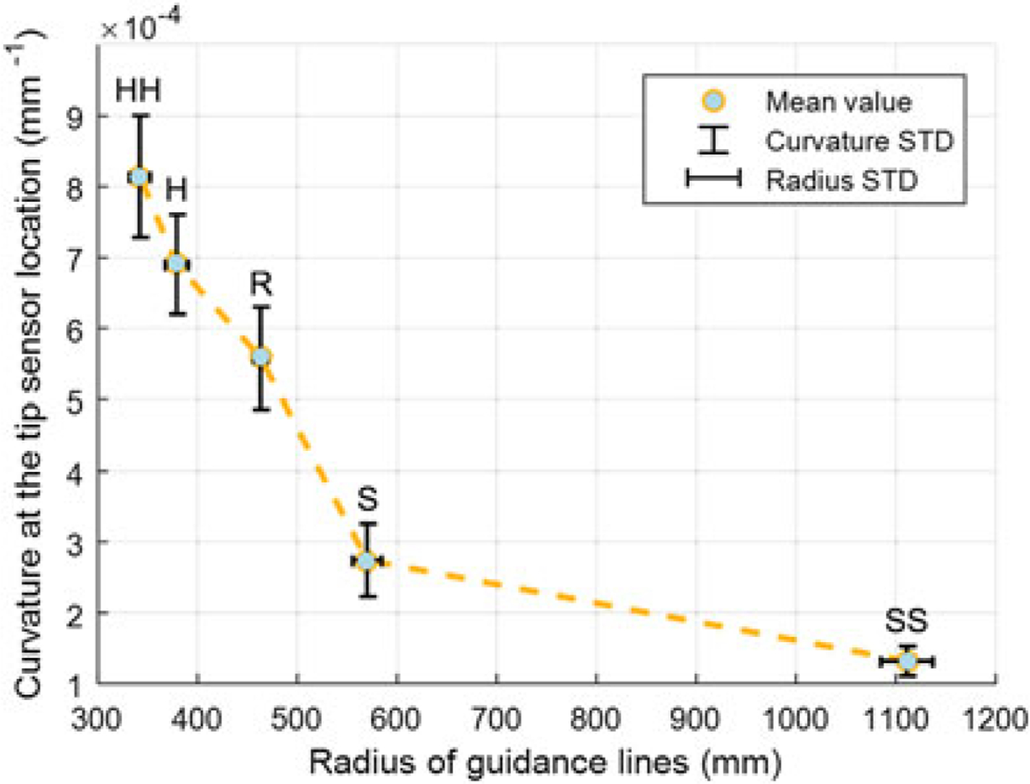
The mapping between the curvatures of tip sensor and corresponding guidance line radius during single-bend insertions into five phantoms with different stiffness. From soft to hard phantom, the curvature increases distinguishably
Targeting experiments
The result of multilayer phantom trials is given in Figure 12. The mean and SD of absolute targeting error for all 24 trials are errimg = 0.61 ± 0.45 mm and errrec = 0.80 ± 0.52 mm. The maximum error is 1.70 mm based on the camera image and 1.72 mm based on the reconstructed needle shape, which are approximately 0.2 mm larger than that in isotropic phantoms, but are still within an acceptable range considering the size of a clinically significant tumor in related biopsy and brachytherapy procedures (a spherical volume with a radius of 5 mm (34, 35). The experimental results demonstrate that the proposed real-time model updating approach could maintain the targeting accuracy despite the mechanical property changes in multilayer phantoms.
Figure 12.
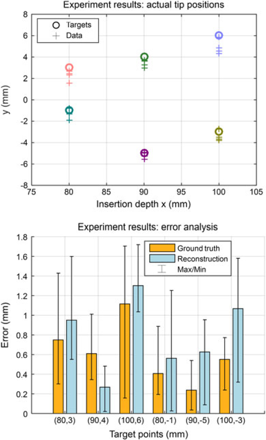
Results of multilayer needle insertion experiments. (a) Six targets are located at 80–100 mm depths and the distribution of the final needle tip position captured by the camera. Different colors illustrate different targets. (b) The absolute tip positioning errors in camera images (ground truth) and reconstructions. The maximum errors are 1.70 mm and 1.72 mm, respectively. The overall average errors are 0.61 ± 0.45 mm and 0.80 ± 0.52 mm, respectively
In vitro insertions
For the set of trials in Experiment 3.4, the absolute targeting error from the camera image and from the reconstructed needle shape were 0.69 ± 0.25 mm and 0.57 ± 0.26 mm, respectively, with maxima at 1.16 mm and 0.94 mm, which are similar to the results acquired in the multi-layer soft plastic phantom trials.
Discussion and conclusion
From the targeting experiment results, both mean errors and maximum errors in multilayer tissues are slightly larger than that in homogeneous tissues. Beef is a relatively soft tissue where blood and fats act as lubricant during needle insertions. From the experiment data, the stiffness of the piece of beef we use is between SS and R in Table 1. This leads to a smaller tip deflection during insertions, and might be a reason for the smaller maximum errors in this experiment. Accuracy requirement for needle placement is determined by the clinically significant size of prostate cancer foci, which however, does not have a generally agreed value currently. In (35) and (36), 0.5 mL tumor volume (about 5 mm radius if spherical) was proposed as the limit for significant prostate cancer foci. This means needle placement errors should smaller than ±2.5 mm. In (25), 3 mm was used as the accuracy limit. Using the proposed setup and the guidance approach in this paper, we consider our result meets the accuracy requirement.
Image-guided interventional surgery is a widely-adopted clinical practice in diagnosis and treatment of prostate cancer. To reduce patient trauma caused by radiation, ineffective needle placements or long-term medical procedure, robot assisted surgery under MRI is a promising solution. Conventional approaches have limitations due to the strong electromagnetic environment, the artefact problem and the low updating frequency, therefore, approaches with less dependence on intraoperative imaging are highly demanded. Our goal is to use the real-time reconstructed shape of our FBG-integrated needle to assist clinicians to perform accurate and safe needle insertion using the in-bore MRI-compatible teleoperated robot. The innovations of this paper mainly incorporate: (1) a fourth-order polynomial shape reconstruction method for an FBG-integrated 20 G bevel tip needle, and comparison among the shape reconstruction approaches in prior work; (2) a model-based computer-assisted navigation method for needle steering; and (3) an adaptive parameter updating method for targeting in inhomogeneous tissue. We performed multiple concept-verification experiments and targeting experiments utilizing the proposed system and methods, including experiments in soft plastic phantoms (average targeting error is 0.40 ± 0.35 mm), in multilayer phantoms (average error is 0.61 ± 0.45 mm) and in bio-tissue (average error is 0.69 ± 0.25 mm).
This is an ongoing work, and future tasks involve improvement of the FBG-integrated needle and extending of the navigation approach in 3D. Although the tip sensor is only 11 mm from the needle tip, there is visible delay before the sensor detects the tissue property change. As shown in Figure 11, there is an 18 mm ‘rising zone’ before the sensor readings become stable and parameters are completely confirmed. As a solution, we are trying to enhance the needle with a center fiber, which is specifically used to capture force applied in the longitudinal direction of the needle. The feasibility of adding such a fiber has been reported in previous FBG-integrated eye-surgery tools developed by our group (37). We believe such a design will make it possible to detect tissue change with much less time delay, thus further improving targeting accuracy.
The needle used in this study has three sensing regions. Two of them (the first two closer to the tip) are very close to each other, which limits the order of interpolation during needle shape reconstruction. Thus, if the needle is rotated multiple times resulting in too many bends in the insertion path, it cannot be accurately reconstructed. Adding more sensors along the needle will effectively improve the shape reconstruction accuracy, and the ability to perform multiple rotations. In addition, the targets in all experiments presented in this paper were fixed, which is not necessarily the case in a clinical scenario. If the target moves during insertion, using the GUI, the operator may decide to rotate the needle earlier or later in order to keep the target still within the reachable region based on the visual guidance provided. With more FBG sensors along the needle, we will be able to plan higher order trajectories to reach moving targets as well.
The methods and experiments in this work were focused on needle steering in 2D. For better utility in clinical practice we will extend this approach to 3D while using an MRI scanner to find the final needle tip position to verify targeting accuracy. In this approach, we could capture MR images during critical insertion stages as an auxiliary feedback to compare with the needle shape reconstructed from the FBG sensors, correct any potential error in the shape estimation, and update the planned trajectory towards the target.
In addition, a complete setup taking consideration of system integration with the MRI table and device sanitation procedures that meet medical standards will help our future in vitro and animal experiments.
Acknowledgements
The authors thank Andreas Fatschel, Anzhu Gao and Yang Wang for their contributions to Matlab simulations and setting up the experiments.
This work has been funded by the National Institutes of Health (NIH) under R01 CA111288 (BRP). Meng Li is supported by China Scholarship Council and National Natural Science Foundation of China under Grant No. 61375106. Gang Li is supported by Link Foundation Fellowship.
References
- 1.Siegel R, Ma J, Zou Z, Jemal A. Cancer statistics. CA Cancer J Clin 2014; 64(1): 9–29. [DOI] [PubMed] [Google Scholar]
- 2.Abolhassani N, Patel R, Moallem M. Needle insertion into soft tissue: a survey. Med Eng Phys 2007; 29(4): 413–431. [DOI] [PubMed] [Google Scholar]
- 3.Podder TK, Beaulieu L, Caldwell B, et al. AAPM and GEC-ESTRO guidelines for image-guided robotic brachytherapy: report of Task Group 192. Med Phys 2014; 41: 101501. [DOI] [PubMed] [Google Scholar]
- 4.Webster RJ, Kim JS, Cowan NJ, et al. Nonholonomic modeling of needle steering. Int J Rob Res 2006; 25(5–6): 509–525. [Google Scholar]
- 5.Abayazid M, Vrooijink GJ, Patil S, et al. Experimental evaluation of ultrasound-guided 3D needle steering in biological tissue. Int J Comput Assist Radiol Surg 2014; 9(6): 931–939. [DOI] [PMC free article] [PubMed] [Google Scholar]
- 6.Patil S, Alterovitz R. Interactive motion planning for steerable needles in 3D environments with obstacles. IEEE RAS and EMBS International Conference on Biomedical Robotics and Biomechatronics (BioRob); Tokyo, Japan; 2010 Sep 26–29; 893–899. [DOI] [PMC free article] [PubMed] [Google Scholar]
- 7.Seifabadi R, Song S-E, Krieger A, et al. Robotic system for MRI-guided prostate biopsy: feasibility of teleoperated needle insertion and ex vivo phantom study. Int J Comput Assist Radiol Surg 2012; 7(2): 181–190. [DOI] [PMC free article] [PubMed] [Google Scholar]
- 8.Fichtinger G, Fiene JP, Kennedy CW, et al. Robotic assistance for ultrasound-guided prostate brachytherapy. Med Image Anal 2008; 12(5): 535–545. [DOI] [PMC free article] [PubMed] [Google Scholar]
- 9.Fichtinger G, DeWeese TL, Patriciu A, et al. System for robotically assisted prostate biopsy and therapy with intraoperative CT guidance. Acad Radiol 2002; 9(1): 60–74. [DOI] [PubMed] [Google Scholar]
- 10.Su H, Shang W, Cole G, et al. Piezoelectrically actuated robotic system for MRI-guided prostate percutaneous therapy. IEEE-ASME T Mech 2014; 20(4): 1920–1932. [DOI] [PMC free article] [PubMed] [Google Scholar]
- 11.Shang WJ, Su H, Li G, Fischer GS. Teleoperation system with hybrid pneumatic-piezoelectric actuation for MRI-guided needle insertion with haptic. IEEE/RSJ International Conference on Intelligent Robots and Systems (IROS); Tokyo, Japan; 2013 Nov 3–7; 4092–4098. [DOI] [PMC free article] [PubMed] [Google Scholar]
- 12.Long J-A, Hungr N, Baumann M, et al. Development of a novel robot for transperineal needle-based interventions: focal therapy, brachytherapy and prostate biopsies. Int J Urol 2012; 188(4): 1369–1374. [DOI] [PubMed] [Google Scholar]
- 13.Yu KK, Hricak H. Imaging prostate cancer. Radiol Clin N Am 2000; 38(1): 59–85. [DOI] [PubMed] [Google Scholar]
- 14.Stoianovici D, Song D, Petrisor D, et al. MRI stealth robot for prostate interventions. Minim Invas Ther Allied Technol 2007; 16(4): 241–248. [DOI] [PMC free article] [PubMed] [Google Scholar]
- 15.Goldenberg AA, Trachtenberg J, Kucharczyk W, et al. Robotic system for closed bore MRI-guided prostatic interventions. IEEE-ASME T Mech 2008; 13(3): 374–379. [Google Scholar]
- 16.Li G, Shang W, Tokuda J, et al. A fully actuated robotic assistant for MRI-guided prostate biopsy and brachytherapy. Proceedings of the SPIE 8671, Medical Imaging 2013: Image-Guided Procedures, Robotic Interventions, and Modeling; Lake Buena Vista, FL, USA; 2013. Feb 9; DOI: 10.1117/12.2007669. [DOI] [PMC free article] [PubMed] [Google Scholar]
- 17.Su H, Cardona DC, Shang W, et al. A MRI-guided concentric tube continuum robot with piezoelectric actuation: a feasibility study. IEEE International Conference on Robotics and Automation (ICRA); Saint Paul, MN, USA; 2012 May 14–18; 1939–1945. [Google Scholar]
- 18.Song S-E, Tokuda J, Tuncali K, et al. Development and preliminary evaluation of a motorized needle guide template for MRI-guided targeted prostate biopsy. IEEE Biomed Eng 2013; 60(11): 3019–3027. [DOI] [PMC free article] [PubMed] [Google Scholar]
- 19.Epaminonda E, Drakos T, Kalogirou C, et al. MRI guided focused ultrasound robotic system for the treatment of gynaecological tumors. Int J Med Robotics Comput Assist Surg 2015. Mar 25. doi: 10.1002/rcs.1653. [DOI] [PubMed] [Google Scholar]
- 20.Yiallouras C, Ioannides K, Dadakova T, et al. Three-axis MR-conditional robot for high-intensity focused ultrasound for treating prostate diseases transrectally. J Therapeut Ultrasound 2015; 3(2): 1–10. [DOI] [PMC free article] [PubMed] [Google Scholar]
- 21.Park Y-L, Elayaperumal S, Daniel B, et al. Real-time estimation of 3-D needle shape and deflection for MRI-guided interventions. IEEE-ASME T Mech 2010; 15(6): 906–915. [DOI] [PMC free article] [PubMed] [Google Scholar]
- 22.Roesthuis RJ, Kemp M, van den Dobbelsteen JJ, Misra S. Three-dimensional needle shape reconstruction using an array of Fiber Bragg Grating sensors. IEEE-ASME T Mech 2014; 19(4): 1115–1126. [Google Scholar]
- 23.Abayazid M, Kemp M, Misra S. 3D flexible needle steering in soft-tissue phantoms using Fiber Bragg Grating sensors. IEEE International Conference on Robotics and Automation (ICRA); Karlsruhe, Germany; 2013 May 6–10; 5843–5849. [Google Scholar]
- 24.Roesthuis RJ, van de Berg NJ, van den Dobbelsteen JJ, Misra S. Modeling and steering of a novel actuated-tip needle through a soft-tissue simulant using Fiber Bragg Grating sensors. IEEE International Conference on Robotics and Automation (ICRA); Seattle, Washington, USA; 2015 May 26–30; 2283–2289. [Google Scholar]
- 25.Seifabadi R, Cho NBJ, Song S-E, et al. Accuracy study of a robotic system for MRI-guided prostate needle placement. Int J Med Robotics Comput Assist Surg 2013; 9(3): 305–316. [DOI] [PMC free article] [PubMed] [Google Scholar]
- 26.Eslami S, Fischer GS, Song S-E, et al. Towards clinically optimized MRI-guided surgical manipulator for minimally invasive prostate percutaneous interventions: constructive design. IEEE International Conference on Robotics and Automation (ICRA); Karlsruhe, Germany; 2013 May 6–10; 1228–1233. [DOI] [PMC free article] [PubMed] [Google Scholar]
- 27.Eslami S, Shang W, Li G, et al. In-bore prostate transperineal interventions with an MRI-guided parallel manipulator: system development and preliminary evaluation. Int J Med Robotics Comput Assist Surg in press; 2015. doi: 10.1002/rcs.1671. [DOI] [PMC free article] [PubMed] [Google Scholar]
- 28.Li M, Gonenc B, Kim K, et al. Development of an MRI-compatible needle driver for in-bore prostate biopsy. IEEE International Conference on Advanced Robotics (ICAR); Istanbul, Turkey; 2015 Jul 27–31; 130–136. [DOI] [PMC free article] [PubMed] [Google Scholar]
- 29.Seifabadi R, Gomez EE, Aalamifar F, et al. Real-time tracking of a bevel-tip needle with varying insertion depth: toward teleoperated MRI-guided needle steering. IEEE/RSJ International Conference on Intelligent Robots and Systems (IROS); Tokyo, Japan; 2013 Nov 3–7; 469–476. [Google Scholar]
- 30.Seifabadi R. Teleoperated MRI-guided prostate needle placement (dissertation). Queen’s University: Kingston, Ontario, Canada, 2013. [Google Scholar]
- 31.Misra S, Reed KB, Schafer BW, et al. Mechanics of flexible needles robotically steered through soft tissue. Int J Rob Res in press; 2010. doi: 10.1177/0278364910369714. [DOI] [PMC free article] [PubMed] [Google Scholar]
- 32.Engh JA, Podnar G, Kondziolka D, Riviere CN. Toward effective needle steering in brain tissue. International Conference of the IEEE Engineering in Medicine and Biology Society; New York, NY, USA; 2006 Aug 30–Sep 3; 559–562. [DOI] [PubMed] [Google Scholar]
- 33.Swaney PJ, Burgner J, Gilbert HB, Webster RJ. A flexure-based steerable needle: high curvature with reduced tissue damage. IEEE T Bio-Med Eng 2012; 60(4): 906–909. [DOI] [PMC free article] [PubMed] [Google Scholar]
- 34.Ploussard G, Epstein JI, Montironi R, et al. The contemporary concept of significant versus insignificant prostate cancer. Eur Urol 2011; 60(2): 291–303. [DOI] [PubMed] [Google Scholar]
- 35.Bak JB, Landas SK, Haas GP. Characterization of prostate cancer missed by sextant biopsy. Clin Prostate Cancer 2003; 2(2): 115–118. [DOI] [PubMed] [Google Scholar]
- 36.Stamey TA, Freiha F, McNeal J, et al. Localized prostate cancer. Cancer Res 1993; 71(3): 933–938. [DOI] [PubMed] [Google Scholar]
- 37.He X, Handa J, Gehlbach P, et al. A submillimetric 3-DOF force sensing instrument with integrated Fiber Bragg Grating for retinal microsurgery. IEEE Int T Bio-Med Eng 2014; 61(2): 522–534. [DOI] [PMC free article] [PubMed] [Google Scholar]


