Abstract
Whilst 2‐ or 5‐OMe groups on the bridging phenylene ring in [{Cp*(dppe)RuC≡C}2(μ‐1,3‐C6H4)]+ have little influence on the electronic structure of this weakly coupled mixed‐valence complex, a 4‐OMe substituent enhances ground state electron delocalization, and increases the intensity of the IVCT transition. Vibrational frequency and TDDFT calculations (LH20t‐D3(BJ), def2‐SVP, COSMO (CH2Cl2)) on ([{Cp*(dppe)RuC≡C}2(μ‐1,3‐C6H3‐n‐OMe)]+ (n=2, 4, 5) models are in excellent agreement with the experimental results. The stronger ground state coupling is attributed to the change in composition of the β‐HOSO brought about by the 4‐OMe group, which is ortho or para to each of the metal fragments. The intensity of the IVCT transition increases with the greater overlap of the β‐HOSO and β‐LUSO, whilst the relative phases of the β‐HOSO and β‐LUSO in the 4‐OMe substituted complex are consistent with predictions of constructive quantum interference from molecular circuit rules.
Keywords: Density Functional Theory, Mixed Valence, Molecular Electronics, Quantum Interference, Spectroelectrochemistry
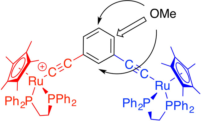
The degree of ground state electronic interaction in the mixed‐valence complex [{Cp*(dppe)RuC≡C}2(μ‐1,3‐C6H4)]+ can be tuned through the introduction of an OMe substituent to the bridging ligand. These effects are sensitive to the position of the substituent, and follow the same patterns as those predicted by quantum circuit rules for weakly coupled molecules in molecular junctions.
Introduction
The influence of the topology, or site of connectivity, on the capacity of a molecular bridge to relay or transmit electronic effects has been clearly demonstrated in the context of both charge transfer processes within donor‐bridge‐acceptor (D‐B‐A) molecules, [1] including mixed‐valence examples (M‐B‐M+),[ 2 , 3 ] and the charge transport processes that underpin the electrical properties of molecular junctions. [4] Assuming efficient D‐B and A‐B coupling, the bridge structures that give rise to stronger coupling between donor and acceptor sites in discrete molecules are usually found to lead to higher molecular conductance when well‐coupled by anchor groups between two electrodes (i.e. within a molecular junction).[ 5 , 6 ] Such observations have led to discussions of the significance (or otherwise) of correlations between molecular charge transfer processes in donor‐acceptor systems, and the charge transport processes within a molecular junction that underpin single molecule conductance.[ 7 , 8 ]
Beyond simple models of charge transport through a molecular junction in terms of coherent tunneling or thermally activated hopping mechanisms, quantum interference patterns also play a critical role in controlling electron transport within molecular junctions. [9] Taking the most common situation of off‐resonance transport within the molecular junction (i.e. transmission by tunneling through the HOMO–LUMO gap), when the transmitted electron waves injected from one electrode at one site of the bridge (r) emerge in‐phase at the collection site connected to the second electrode (s), the constructive quantum interference (CQI) effects that arise result in pronounced electrical conductance of the junction (Figure 1a). Conversely, when the injected electron wave emerges as a sum of out‐of‐phase amplitudes (destructive quantum interference, DQI), there is a significant decrease in electron transmission and hence decreased electrical conductance (Figure 1b). [10]
Figure 1.
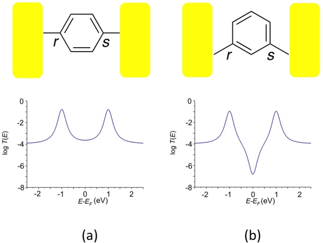
Cartoon depictions of molecular junctions illustrating the sites at which electrons are injected into the molecular π‐system from the left electrode (r) and collected at the right electrode (s) through molecular backbones together with associated plots of logT(E) vs E‐EF illustrating: a) constructive quantum interference (CQI); b) destructive quantum interference (DQI).
Within the framework of Landauer‐Büttiker theory, these quantum interference effects give rise to characteristic features in the transmission function, T(E), which describes the probability of the transmission of an electron of energy E passing through the junction. CQI effects result in significant values of T(E), and relatively high through‐molecule conductance for a broad range of electron energies in the middle of the HOMO–LUMO gap (Figure 1a). In contrast, DQI leads to a sharp dip in the transmission function centered on the specific energy where maximum cancellation of T(E) occurs, which significantly decreases mid‐gap conductance (Figure 1b). [11]
A characteristic feature of DQI within molecular junctions is the sensitivity of the position of the conductance dip relative to the Fermi energy (and hence molecular conductivity) to the structure of the molecular backbone, [12] including the electronic nature, position and conformation of pendant groups around the molecular bridge. [13] These effects have been explored at a range of levels of theory, and demonstrated in molecular junctions formed from 2‐, 4‐, and 5‐methoxy substituted derivatives of 1,3‐diethynyl benzene (1–4, Scheme 1). [14]
Scheme 1.
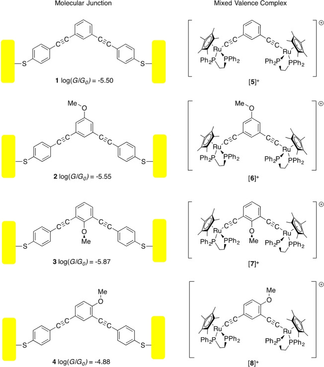
Cartoons showing the molecular junctions and associated single molecule conductivity of compounds 1–4, and the mixed‐valence complexes [5–8]+.
Beyond molecular junctions, the concept that DQI effects may play a role in mediating the charge transfer processes within donor‐acceptor systems has been proposed by Grozema. [15] However, while the effects of bridge‐substituents on the electronic coupling in donor‐acceptor systems, including weakly‐coupled mixed‐valence complexes, have been explored, [16] strong experimental and computational evidence linking the concept of QI with the magnitude of electronic coupling in such molecular charge‐transfer systems has been elusive. [17]
Results and Discussion
Mixed‐valence complexes based on 1,3‐diethynyl benzene bridging ligands are well known, and display the weak coupling expected of a cross‐conjugated bridge. [18] In order to explore the potential analogies of the substituent‐tunable DQI phenomena observed in molecular junctions formed from 1–4 [14] with the influence of substituents on mixed‐valence complexes, computational studies were carried out at the DFT (LH20t‐D3(BJ)/def2‐SVP, COSMO(CH2Cl2)) level of theory on complexes [5′]n+–[8′]n+ (n=0, 1) (Scheme 1, Table S1; the ′ notation is used to designate a computational model, as distinct from a synthetic system) and structurally simpler systems featuring {Ru(dmpe)Cp} end‐groups ([5 a′–8 a′]+) (Scheme S1, Table S1). [19] In each case, the molecular structures were fully optimized using starting structures derived from an approximately C2v–symmetric arrangement. Given the close agreement between the two sets of results, the discussion below is presented with reference to the larger, more experimentally relevant {Ru(dppe)Cp*} series [5′–8′]n+.
The optimized structures give clear evidence for the different electronic environments at the metal centers, with the longer Ru−P, shorter Ru−Cα and longer Cα≡Cβ bond lengths associated with one metal fragment clearly identifying the site of oxidation (nominally designated Ru(1), Table S1). These structural differences at the metal centers are reflected in the composition of the frontier orbitals (Figure 2, Table S2). As is typical of formally ruthenium(III) arylacetylide complexes, [20] the unpaired electron and the β‐spin lowest‐unoccupied spin orbital (β‐LUSO) in the parent complex [5′]+ is distributed over one metal center (i.e. Ru(1)) and the associated acetylide ligand, as well as the central ring; the β‐spin high‐occupied spin orbital (β‐HOSO) is similar in structure and distributed over the other metal‐acetylide fragment (Figure 2, Table S2). A weak IVCT band (i.e. the β‐HOSO→β‐LUSO transition) is calculated at 3548 cm−1 (f osc=0.0174) (Figure 3, Table S2). The electronic structure of [5′]+ is therefore consistent with the description of this compound as a localized mixed‐valence complex, and in good agreement with previous experimental studies. [18a]
Figure 2.
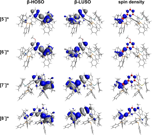
Plots of the β‐HOSO and β‐LUSO (contours plotted at ±0.02 (e/bohr3)1/2) and spin density (contours plotted at ±0.002 (e/bohr3)1/2) of [5′–8′]+.
Figure 3.
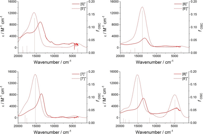
Plots showing the results of TDDFT calculations at the LH20t/def2‐SVP//LH20t‐D3(BJ)/def2‐SVP, COSMO (CH2Cl2) level of theory from [5′–8′]+ as stick spectra, and as spectra broadened with Gaussian line shapes with linewidths of 1100 cm−1 together with spectra of [5]+–[8]+ obtained by spectroelectrochemical methods.
When placed in the 5‐position of the central ring, the OMe group sits at a node in both the β‐HOSO and β‐LUSO (Figure 2), and consequently, the molecular structure (Table S1) and frontier orbital composition (Table S2) of [6′]+ are essentially identical to those of [5′]+. A weak IVCT band (β‐HOSO→β‐LUSO) is calculated at 3217 cm−1 (f osc=0.0066) (Figure 3, Table S2). The similar mixed‐valence character of [5′]+ and [6′]+ follows the predictions made for the influence of substituents at the 5‐position on the energy of the DQI dip in 1,3‐contacted benzene rings, [13a] and experimentally verified by the negligible influence of the 5‐OMe moiety on the conductance of the 1,3‐diethynyl derivative [2] relative to [1]. [14]
Although the 2‐position is predicted to be able to tune the position of a DQI dip of a 1,3‐connected benzene ring in a molecular junction, [13a] in [7′]+ steric interactions with the flanking ethynyl groups prevent the OMe group from adopting a position co‐planar with the phenyl ring (Scheme 1). Therefore, although the 2‐position is “QI active”, the restricted conformation of the OMe group means it can act only as an inductively electron‐withdrawing group with a small role in tuning the energy of the IVCT band. The conformational decoupling of the π‐type O(2p) orbital of the 2‐OMe moiety from π‐system of the bridging ligand means this group has little influence on the over‐arching QI effects that are propagated through the π‐electron system and hence has essentially no impact on the mixed‐valence character of [7′]+ relative to [5′]+ (Figure 2, Figure 3, Table S1, Table S2). The conformationally induced ‘tuning’ of the influence of the 2‐OMe group on the DQI features that impact upon the molecular conductance of [3] (Scheme 1) has been discussed elsewhere. [14]
In contrast, the 4‐OMe group in [8′]+ has a subtle but important role in modifying the electronic and spectroscopic properties of this complex relative to the other examples noted above. The 4‐OMe group sits either para or ortho to each of the metal acetylide fragments and is therefore linearly conjugated to both, even though the metal fragments are not linearly conjugated to each other i.e. the metal centers and 4‐OMe group are cross‐conjugated. The Ru(1)‐P(11)/P(12) bond lengths are shorter in [8′]+ than the other members of the series, indicating an interaction between the electron‐donating OMe group and the para‐positioned metal acetylide (i.e. Ru(1)−Cα≡Cβ) (Table S1). The majority of the β‐LUSO character is distributed over the Ru(1)−Cα≡Cβ chain, with the electron donating character of the OMe moiety also resulting in some increased contribution from the bridging ligand to the β‐LUSO relative to [5′]+. Rather crucially, the 4‐OMe group also results in a small but important increase in the contribution from the Ru(1)−Cα≡Cβ(1) fragment to the β‐HOSO that is not evident in the other derivatives (Figure 2, Table S2).
The increased ground‐state electronic interactions between the metal fragments in [8′]+ revealed by the composition of the β‐HOSO also increases the orbital overlap between the β‐HOSO and β‐LUSO (Figure 2, Table S2). In turn, this results in the IVCT‐like β‐HOSO→β‐LUSO transition having greater intensity than the other members of the series (4812 cm−1, f osc =0.0902). This transition results in a low energy band in the simulated UV/Vis‐NIR spectra that is more apparent in the other examples (Figure 3); the higher energy spectral features of [8′]+ are qualitatively similar to those of [5′–7′]+ (Figure S1).
The above results can also be understood from the viewpoint of perturbation theory. From the parent [5′]+ a local perturbation at the n‐position of the central ring can only induce a coupling between the β‐HOSO and β‐LUSO of [5′]+, if (a) both orbitals have a non‐zero amplitude at the n‐position and (b) the magnitude of the perturbation is finite. Therefore, since both orbitals have no amplitude at position 5 (meta to both ethynyl moieties), a local perturbation at the 5‐position as in [6′]+ does not induce a coupling between the β‐HOSO and β‐LUSO and has negligible effect (Figure 2, Table S1, Table S2). On the other hand, the β‐HOSO and β‐LUSO of [5′]+ have non‐zero amplitudes at position 2 (ortho to both ethynyl fragments). However, in the case of the 2‐OMe substituted complex [7′]+ the magnitude of the perturbation is negligible, because due to steric hindrance of the OMe group at this position, the π‐system of the OMe group is orthogonal to, and therefore decoupled from, the π‐system of the central ring (Figure 2). [14] Therefore the presence of the 2‐OMe group has negligible effect on the electronic structure and optical properties of [7′]+, which are similar to those of [5′]+ (Table S1, Table S2). Only the introduction of the OMe group at position 4, as in [8′]+, satisfies both of the above conditions (a) and (b) and induces a stronger mixing of the β‐HOSO and β‐LUSO in [8′]+ than in [5′]+, [6′]+ or [7′]+. In turn, this leads to a more intense β‐HOSO→β‐LUSO electronic transition in the 4‐OMe substituted complex (Figure 2, Figure 3, Table S1, Table S2).
Intriguingly, the increased ground‐state electronic interaction between Ru(1) and Ru(2) brought about by the introduction of the 4‐OMe group in mixed‐valence [8′]+ compared with [5′–7′]+ and associated increases in IVCT band intensity follow the substituent induced trends in molecular conductance reported earlier, i.e. 4‐OMe functionalized 4 displays a higher single‐molecule conductance than the parent, 2‐OMe and 5‐OMe derivatives 1–3 (Scheme 1). [14] Beyond the analogies of the stronger electronic coupling in mixed‐valence [8′]+ and the more efficient electron transport properties of 4, further parallels can be found in the phases of the frontier molecular orbitals that underpin the quantum interference effects noted above. According to the “orbital product rule”, [9] a qualitative indication of the mid‐gap electron transport probability (i.e. conductance) through a molecule weakly coupled to two electrodes can be obtained from the phase and amplitude of the HOMO and LUMO at the points of molecule‐electrode contact (Figure 1). [21] Provided there is significant orbital amplitude at the site of electron injection (r) and collection (s), when the sign of the product of the MO coefficients at atoms r and s in the HOMO is opposite to the sign of the product of the coefficients of those atoms in the LUMO then conductance is enhanced by CQI. Conversely, if the product of the MO coefficients at r and s are the same in both the HOMO and LUMO then conductance is reduced by DQI. [14]
Although a discrete mixed‐valence complex would not be described in the same terms as a molecular junction, the primary analysis underpinning the orbital product rule treats the Green's functions of the metal electrodes and molecule separately, with the product rule arising from the matrix elements of the zeroth Green's function of only the molecular part. In the case of [8′]+, the β‐HOSO has the same phase at both the ruthenium centers whilst the β‐LUSO has opposite phase at the metal atoms (Figure 2), which follows the orbital product rule for enhanced conductance. The role substituents groups such as the OMe moiety in the compounds and complexes of Scheme 1 play in promoting amplitude of the appropriate phase at various points in the frontier orbitals may therefore be suggested as the critical factor controlling both the electrical properties of molecular junctions and the electronic character of mixed‐valence complexes.
To verify these suggestions concerning chemical structure—electronic property effects, mixed‐valence complexes derived from one‐electron oxidation of the experimental systems 5–8 (Scheme 1) were chosen for study by UV/Vis‐NIR and IR spectroelectrochemical methods, complementing and extending studies of the parent complex 5 reported earlier. [18a] The structures of each of 5–8 have been determined crystallographically (Figure S2, Table S3, Table S4). [22]
In CH2Cl2 solution containing 0.1 M NBu4PF6 as supporting electrolyte, each complex 5–8 undergoes two sequential one‐electron oxidation processes at a platinum working electrode (Figure S3, Table S4). The first oxidation process of the 4‐OMe substituted complex 8 is 70–170 mV more favorable than other members of the series, reflecting the mutual influence of the linearly conjugated, para‐disposed OMe and Ru(1) half‐sandwich metal fragments. The enhanced stability of [8]+ towards disproportionation is reflected in the greater separation of the two redox potentials (ΔE1‐2) than found for other members of the series (Figure S3, Table S4). Given that similar solvation energies, ion‐pairing interactions, electrostatic and magnetic interactions and reorganization energies are expected to be associated with the redox processes of 5–8, the larger ΔE1‐2 offered by 8 (290 mV, c.f. 5–7 210–230 mV) points to greater resonance stabilization energy in [8]+ than in the other members of the series. [23] However, partitioning that additional stabilization between the resonance effects arising from the OMe group and those arising from the greater delocalization between the metal fragments is rather challenging.
The IR spectra of [5–8]n+ (n=0, 1, 2) obtained through spectroelectrochemical methods provide further indications of the unique role of the 4‐OMe group in tuning ground state electronic interactions between the metal centers through the bridging ligand (Figure 4). Upon one‐electron oxidation within the spectroelectrochemical cell, the single ν(C≡C) band of 5 (2060 cm−1) evolves to a distinct two‐band pattern (2052, 1932 cm−1) that characterizes the mixed‐valence species [5]+, which is clearly localized on the IR timescale. [18a] Further oxidation gives the homo‐valent dication [5]2+ which is characterized by a single ν(C≡C) band (1935 cm−1) (Figure S4). Very similar spectral profiles are observed for [6]n+ and [7]n+ (n=0, 1, 2; Figure 4, Figure S4). However, while the ν(C≡C) bands in homovalent 8 (2064 cm−1) and [8]2+ (1929 cm−1) are comparable with the spectra of other members of the series, the ν(C≡C) bands in the 4‐OMe substituted mixed valence derivative [8]+ are broadened and fall at significantly lower frequencies (2033, 1905 cm−1) (Figure 4). We suspect that the broadening of the IR active ν(C≡C) bands in [8]+ arises from the coupling of the direction of the vibrational (stretching) motion with the electron‐transfer processes leading to the IVCT transition. Calculated vibrational frequencies from 5′–8′ and [5′–8′]+ are in broad general agreement with these observations (Table S5).
Figure 4.
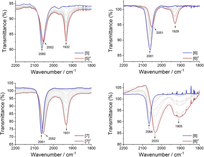
IR spectra collected during the oxidation of 5–8 to [5–8]+ in a spectroelectrochemical cell (CH2Cl2/0.1 M NBu4PF6).
The UV/Vis‐NIR spectra collected from [5–8] and [5–8]+ by spectroelectrochemical methods (Figure 5) are in close agreement with the results of TDDFT calculations over a wide range of wavelengths (Figure S1). In the NIR region, extremely weak bands at energies below 8000 cm−1 can be observed in the spectra of the mixed‐valence products [5–7]+ that are not apparent in the spectra of the neutral or dicationic analogues (Figure 3, Figure 5, Figure S5). These weak bands are assigned to the IVCT processes in the weakly coupled mixed‐valence complexes, in agreement with the results of the TDDFT calculations reported above (Figure 3, Table S2). Together, the computational studies with [5′–7′]+ and spectroelectrochemical results of [5–7]+ collectively indicate little influence from the OMe group in the 5‐ or conformationally restricted 2‐positions on the electronic structure of the 1,3‐diethynyl benzene bridged mixed‐valence complex.
Figure 5.
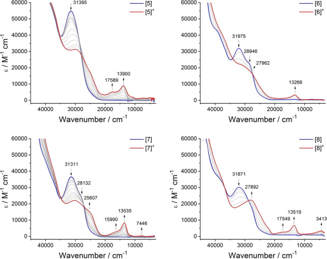
Vis‐NIR spectra collected during the oxidation of [5–8] to [5–8]+ in a spectroelectrochemical cell (CH2Cl2/0.1 M NBu4PF6).
Significantly, a relatively intense, low energy electronic absorption envelope, unique to the monocation [8]+, and therefore also assigned to IVCT processes, can also be observed in the range ca. 8000–2000 cm−1 (Figure 5, Figure S5) in good agreement with the TDDFT calculations from [8′]+ (Figure 3, Table S2). Interestingly, this low energy region is also modelled extremely well by TDDFT calcuations carried out with the structurally reduced model [8 a′]+ (Figure S6) However, as has been discussed widely elsewhere, the extraction of the authentic IVCT band‐shape from complex absorption envelopes is complicated by factors such as the distribution of molecular conformers in solution, [24] and overlapping electronic transitions of similar energy but different electronic character (e.g. dd transitions, LMCT/MLCT bands). [25] These factors make the application of Hush‐style analyses of the IVCT component of the NIR band envelope, and hence determination of the underlying electronic coupling parameter, subjective to the deconvolution conditions employed and correct assignment of the contributing spectroscopic transitions. The use of DFT models with an appropriate functional are recognised as providing a more complete description of the electronic structures of mixed‐valence complexes, even if lacking the appeal of a single numerical parameter. Here, the DFT calculations employing a local hybrid functional suggest that the enhanced electronic interactions between the metal centers in [8]+ evinced by both the IR and NIR spectra can be attributed to the unique delocalization and parity of the β‐HOSO and β‐LUSO brought about by the 4‐OMe substituent.
Conclusion
The effect of 2‐, 4‐ and 5‐OMe substituents on the electronic coupling in a 1,3‐diethynylbenzene‐bridged mixed‐valence complex has been explored with DFT calculations using a local hybrid functional and experimental spectroelectrochemical measurements. The correlation of the results with the predictions made on the basis of the orbital product rule offers a new avenue for the design and exploration of mixed‐valence complexes and intramolecular charge transfer processes. The use of a simple, selectively positioned OMe group to enhance the intramolecular coupling between the metal centers in the 1,3‐diethynyl benzene‐bridged mixed‐valence complex provides further scope for tuning MV characteristics in common frameworks, and also points to the potential use of MV complexes as probes or predictive models for DQI effects in molecular junctions.
Conflict of interest
The authors declare no conflict of interest.
1.
Supporting information
As a service to our authors and readers, this journal provides supporting information supplied by the authors. Such materials are peer reviewed and may be re‐organized for online delivery, but are not copy‐edited or typeset. Technical support issues arising from supporting information (other than missing files) should be addressed to the authors.
Supporting Information
Supporting Information
Supporting Information
Supporting Information
Supporting Information
Acknowledgements
This work was supported by the Australian Research Council (DP190100073, DP190100074). Work in Berlin was funded by the Deutsche Forschungsgemeinschaft (DFG, German Research Foundation) under Germany's Excellence Strategy EXC 2008/1 390540038 UniSysCat. Exchange between UWA and TUB was aided by a Frederich Wilhelm Bessel Research Award to P.J.L. from the Alexander von Humboldt Fondation. S.A.M. gratefully acknowledges an ARC Future Fellowship (FT200100243). M.N. and M. Korb gratefully acknowledge support from the Forrest Research Foundation. D.P.H. gratefully acknowledges the award of the Raoul Robellza Kahan Honours Scholarship. The crystallographic structures were determined using facilities and instrumentation provided by the Centre for Microscopy, Characterisation and Analysis (CMCA), University of Western Australia. Open Access publishing facilitated by The University of Western Australia, as part of the Wiley ‐ The University of Western Australia agreement via the Council of Australian University Librarians.
Dedicated to Professor George A. Koutsantonis, colleague, mentor, and friend, on the occasion of his 60th Birthday.
D. P. Harrison, R. Grotjahn, M. Naher, S. M. B. H. Ghazvini, D. M. Mazzucato, M. Korb, S. A. Moggach, C. Lambert, M. Kaupp, P. J. Low, Angew. Chem. Int. Ed. 2022, 61, e202211000; Angew. Chem. 2022, 134, e202211000.
Contributor Information
Prof. Martin Kaupp, Email: martin.kaupp@tu-berlin.de.
Prof. Paul J. Low, Email: paul.low@uwa.edu.au.
Data Availability Statement
The data that support the findings of this study are available in the supplementary material of this article.
References
- 1. Wanko M., Houmoller J., Stochkel K., Kirketerp M. B. S., Petersen M. A., Nielsen M. B., Nielsen S. B., Rubio A., Phys. Chem. Chem. Phys. 2012, 14, 12905–12911. [DOI] [PubMed] [Google Scholar]
- 2.
- 2a. Halet J. F., Lapinte C., Coord. Chem. Rev. 2013, 257, 1584–1613; [Google Scholar]
- 2b. Kaupp M., Guckel S., Renz M., Klawohn S., Theilacker K., Parthey M., Lambert C., J. Comput. Chem. 2016, 37, 93–102. [DOI] [PubMed] [Google Scholar]
- 3.
- 3a. Capodilupo A.-L., Fabiano E., Franco L., Gambino S., Leoncini M., Accorsi G., Gigli G., J. Phys. Chem. A 2021, 125, 7840–7851; [DOI] [PubMed] [Google Scholar]
- 3b. Chen H. W., Mallick S., Zou S. F., Meng M., Liu C. Y., Inorg. Chem. 2018, 57, 7455–7467. [DOI] [PubMed] [Google Scholar]
- 4.
- 4a. Sangtarash S., Huang C. C., Sadeghi H., Sorohhov G., Hauser J., Wandlowski T., Hong W. J., Decurtins S., Liu S. X., Lambert C. J., J. Am. Chem. Soc. 2015, 137, 11425–11431; [DOI] [PubMed] [Google Scholar]
- 4b. Manrique D. Z., Al-Galiby Q., Hong W. J., Lambert C. J., Nano Lett. 2016, 16, 1308–1316. [DOI] [PubMed] [Google Scholar]
- 5. Kiguchi M., Kaneko S., Phys. Chem. Chem. Phys. 2013, 15, 2253–2267. [DOI] [PubMed] [Google Scholar]
- 6. Arroyo C. R., Tarkuc S., Frisenda R., Seldenthuis J. S., Woerde C. H. M., Eelkema R., Grozema F. C., van der Zant H. S. J., Angew. Chem. Int. Ed. 2013, 52, 3152–3155; [DOI] [PubMed] [Google Scholar]; Angew. Chem. 2013, 125, 3234–3237. [Google Scholar]
- 7. Launay J. P., Actual. Chim. 1996, 92–98. [Google Scholar]
- 8.
- 8a. Launay J. P., Eur. J. Inorg. Chem. 2020, 329–341; [Google Scholar]
- 8b. Launay J. P., Coord. Chem. Rev. 2013, 257, 1544–1554. [Google Scholar]
- 9. Lambert C. J., Liu S. X., Chem. Eur. J. 2018, 24, 4193–4201. [DOI] [PubMed] [Google Scholar]
- 10. Markussen T., Stadler R., Thygesen K. S., Nano Lett. 2010, 10, 4260–4265. [DOI] [PubMed] [Google Scholar]
- 11. Andrews D. Q., Solomon G. C., Goldsmith R. H., Hansen T., Wasielewski M. R., Van Duyne R. P., Ratner M. A., J. Phys. Chem. C 2008, 112, 16991–16998. [Google Scholar]
- 12.
- 12a. Guédon C. M., Valkenier H., Markussen T., Thygesen K. S., Hummelen J. C., van der Molen S. J., Nat. Nanotechnol. 2012, 7, 305–309; [DOI] [PubMed] [Google Scholar]
- 12b. Lambert C. J., Chem. Soc. Rev. 2015, 44, 875–888; [DOI] [PubMed] [Google Scholar]
- 12c. Solomon G. C., Andrews D. Q., Goldsmith R. H., Hansen T., Wasielewski M. R., Van Duyne R. P., Ratner M. A., J. Am. Chem. Soc. 2008, 130, 17301–17308. [DOI] [PubMed] [Google Scholar]
- 13.
- 13a. Garner M. H., Solomon G. C., Strange M., J. Phys. Chem. C 2016, 120, 9097–9103; [Google Scholar]
- 13b. Andrews D. Q., Solomon G. C., Van Duyne R. P., Ratner M. A., J. Am. Chem. Soc. 2008, 130, 17309–17319. [DOI] [PubMed] [Google Scholar]
- 14. Jiang F., Trupp D. I., Algethami N., Zheng H. N., He W. X., Alqorashi A., Zhu C. X., Tang C., Li R. H., Liu J. Y., Sadeghi H., Shi J., Davidson R., Korb M., Sobolev A. N., Naher M., Sangtarash S., Low P. J., Hong W. J., Lambert C. J., Angew. Chem. Int. Ed. 2019, 58, 18987–18993; [DOI] [PubMed] [Google Scholar]; Angew. Chem. 2019, 131, 19163–19169. [Google Scholar]
- 15.
- 15a. Gorczak N., Renaud N., Galan E., Eelkema R., Siebbeles L. D. A., Grozema F. C., Phys. Chem. Chem. Phys. 2016, 18, 6773–6779; [DOI] [PubMed] [Google Scholar]
- 15b. Gorczak N., Renaud N., Tarkuc S., Houtepen A. J., Eelkema R., Siebbeles L. D. A., Grozema F. C., Chem. Sci. 2015, 6, 4196–4206; [DOI] [PMC free article] [PubMed] [Google Scholar]
- 15c. Kocherzhenko A. A., Siebbeles L. D. A., Grozema F. C., J. Phys. Chem. Lett. 2011, 2, 1753–1756. [Google Scholar]
- 16.
- 16a. Makhoul R., Groizard T., Hamon P., Roisnel T., Dorcet V., Kahlal S., Halet J. F., Hamon J. R., Lapinte C., Eur. J. Inorg. Chem. 2020, 2624–2638; [Google Scholar]
- 16b. Fan Y., Li H. M., Zou G. D., Zhang X., Pan Y. L., Cao K. K., Zhang M. L., Ma P. L., Lu H. T., Organometallics 2017, 36, 4278–4286; [Google Scholar]
- 16c. Lepont J., Roisnel T., Hamon J. R., Lapinte C., Eur. J. Inorg. Chem. 2021, 5060–5068; [Google Scholar]
- 16d. Shultz D. A., Lee H., Kumar R. K., Gwaltney K. P., J. Org. Chem. 1999, 64, 9124–9136. [Google Scholar]
- 17.
- 17a. Gao H., Mallick S., Cao L. J., Meng M., Cheng T., Chen H. W., Liu C. Y., Chem. Eur. J. 2019, 25, 3930–3938; [DOI] [PubMed] [Google Scholar]
- 17b. Kirk M. L., Shultz D. A., Stasiw D. E., Habel-Rodriguez D., Stein B., Boyle P. D., J. Am. Chem. Soc. 2013, 135, 14713–14725. [DOI] [PubMed] [Google Scholar]
- 18.
- 18a. Fox M. A., Farmer J. D., Roberts R. L., Humphrey M. G., Low P. J., Organometallics 2009, 28, 5266–5269; [Google Scholar]
- 18b. Weyland T., Costuas K., Toupet L., Halet J. F., Lapinte C., Organometallics 2000, 19, 4228–4239; [Google Scholar]
- 18c. Weyland T., Costuas K., Mari A., Halet J. F., Lapinte C., Organometallics 1998, 17, 5569–5579; [Google Scholar]
- 18d. Colbert M. C. B., Lewis J., Long N. J., Raithby P. R., Younus M., White A. J. P., Williams D. J., Payne N. N., Yellowlees L., Beljonne D., Chawdhury N., Friend R. H., Organometallics 1998, 17, 3034–3043. [Google Scholar]
- 19. Ladjarafi A., Costuas K., Meghezzi H., Halet J. F., J. Mol. Model. 2015, 21, 71. [DOI] [PubMed] [Google Scholar]
- 20.
- 20a. Low P. J., Bock S., Electrochim. Acta 2013, 110, 681–692; [Google Scholar]
- 20b. Schauer P. A., Low P. J., Eur. J. Inorg. Chem. 2012, 390–411. [Google Scholar]
- 21. Yoshizawa K., Tada T., Staykov A., J. Am. Chem. Soc. 2008, 130, 9406–9413. [DOI] [PubMed] [Google Scholar]
- 22.Deposition numbers 2163741, 2163064, 2163065 and 2163066 contain the supplementary crystallographic data for this paper. These data are provided free of charge by the joint Cambridge Crystallographic Data Centre and Fachinformationszentrum Karlsruhe Access Structures service.
- 23.
- 23a. D′Alessandro D. M., Keene F. R., Chem. Soc. Rev. 2006, 35, 424–440; [DOI] [PubMed] [Google Scholar]
- 23b. Winter R. F., Organometallics 2014, 33, 4517–4536; [Google Scholar]
- 23c. Gückel S., Safari P., Ghazvini S. M. B. H., Hall M. R., Gluyas J. B. G., Kaupp M., Low P. J., Organometallics 2021, 40, 346–357. [Google Scholar]
- 24.
- 24a. Gückel S., Gluyas J. B. G., Eaves S. G., Safari P., Yufit D. S., Sobolev A. N., Kaupp M., Low P. J., Chem. Eur. J. 2019, 25, 8837–8853; [DOI] [PubMed] [Google Scholar]
- 24b. Gluyas J. B. G., Gückel S., Kaupp M., Low P. J., Chem. Eur. J. 2016, 22, 16138–16146; [DOI] [PubMed] [Google Scholar]
- 24c. Parthey M., Gluyas J. B. G., Fox M. A., Low P. J., Kaupp M., Chem. Eur. J. 2014, 20, 6895–6908; [DOI] [PubMed] [Google Scholar]
- 24d. Parthey M., Gluyas J. B. G., Schauer P. A., Yufit D. S., Howard J. A. K., Kaupp M., Low P. J., Chem. Eur. J. 2013, 19, 9780–9784; [DOI] [PubMed] [Google Scholar]
- 24e. Fitzgerald E. C., Ladjarafi A., Brown N. J., Collison D., Costuas K., Edge R., Halet J. F., Justaud F., Low P. J., Meghezzi H., Roisnel T., Whiteley M. W., Lapinte C., Organometallics 2011, 30, 4180–4195; [Google Scholar]
- 24f. Burgun A., Gendron F., Sumby C. J., Roisnel T., Cador O., Costuas K., Halet J. F., Bruce M. I., Lapinte C., Organometallics 2014, 33, 2613–2627; [Google Scholar]
- 24g. Costuas K., Cador O., Justaud F., Le Stang S., Paul F., Monari A., Evangelisti S., Toupet L., Lapinte C., Halet J. F., Inorg. Chem. 2011, 50, 12601–12622. [DOI] [PubMed] [Google Scholar]
- 25. Demadis K. D., Hartshorn C. M., Meyer T. J., Chem. Rev. 2001, 101, 2655–2685. [DOI] [PubMed] [Google Scholar]
Associated Data
This section collects any data citations, data availability statements, or supplementary materials included in this article.
Supplementary Materials
As a service to our authors and readers, this journal provides supporting information supplied by the authors. Such materials are peer reviewed and may be re‐organized for online delivery, but are not copy‐edited or typeset. Technical support issues arising from supporting information (other than missing files) should be addressed to the authors.
Supporting Information
Supporting Information
Supporting Information
Supporting Information
Supporting Information
Data Availability Statement
The data that support the findings of this study are available in the supplementary material of this article.


