

Abstract
Membrane tension underlies a range of cell physiological processes. Strong adhesion of the simple red cell is used as a simple model of a spread cell with a finite membrane tension—a state which proves useful for studies of both membrane rupture kinetics and atomic force microscopy (AFM) probing of native structure. In agreement with theories of strong adhesion, the cell takes the form of a spherical cap on a substrate densely coated with poly-L-lysine. The spreading-induced tension, σ, in the membrane is ∼1 mN/m, which leads to rupture over many minutes; and σ is estimated from comparable rupture times in separate micropipette aspiration experiments. Under the sharpened tip of an AFM probe, nano-Newton impingement forces (10–30 nN) are needed to penetrate the tensed erythrocyte membrane, and these forces increase exponentially with tip velocity (∼nm/ms). We use the results to clarify how tapping-mode AFM imaging works at high enough tip velocities to avoid rupturing the membrane while progressively compressing it to a ∼20-nm steric core of lipid and protein. We also demonstrate novel, reproducible AFM imaging of tension-supported membranes in physiological buffer, and we describe a stable, distended network consistent with the spectrin cytoskeleton. Additionally, slow retraction of the AFM tip from the tensed membrane yields tether-extended, multipeak sawtooth patterns of average force ∼200 pN. In sum we show how adhesive tensioning of the red cell can be used to gain novel insights into native membrane dynamics and structure.
INTRODUCTION
Recent work on a range of nucleated cells (Raucher and Sheetz, 1999; Dai et al., 1998) as well as the simple erythrocyte (Hochmuth and Marcus, 2002) has suggested that the lipid bilayer of many if not most cells sustains a nonzero tension up to ∼0.1 mN/m. This membrane tension regulates a wide range of processes such as cell spreading (Raucher and Sheetz, 2000), but the implications of this for molecular substructures and membrane stability have yet to be fully established. While nucleated cells certainly possess many mechanisms of lipid transport such as exocytosis that modulate bilayer tension (Raucher and Sheetz, 1999), such processes are lacking in red cells and make the erythrocyte ideal for studies involving or exploiting membrane tension. The red cell has also long provided a model membrane for cell biology with widely shared lipid, protein, and glycosylated structures offering broad insights (Mohandas and Evans, 1994; Boal, 2002).
We exploit strong adhesion of the red cell and this cell's fixed total area and volume to significantly augment the basal membrane tension. Over time, a sustained tension on model bilayers is known to cause rupture (Evans and Ludwig, 2000). We show the same is true for intact erythrocytes. We also use the characteristic rupture time of adherent cells plus separate micropipette aspiration experiments to determine the average adhesion-induced tension. Before lysis, we show that atomic force microscopy (AFM) probing and imaging of the tensed membrane is both possible and revealing. Rate dependencies are again the focus of our studies, but our overall AFM approach is schematically related to one recently applied to the electromotility of cell membranes (Zhang et al., 2001). In those studies a cell held with a tension in a micropipette was electrically stimulated and simultaneously probed for displacements with an AFM tip. Our own conclusions about membrane structure and stability may be as broad, but our efforts are certainly relevant to red cells since they are known to experience large, rate-dependent deformations in blood flow which have long motivated investigations by micropipette aspiration (e.g., Evans and Skalak, 1980; Discher et al., 1998; Waugh and Evans, 1979) or optical tweezers (Henon et al., 1999; Lenormand et al., 2001). Red cells are also known to adhere to other cells including phagocytes in pathological conditions of erythrophagocytosis (Garratty, 2001) as well as in the process of recognition and clearance by the liver and spleen (Oldenborg et al., 2000). Sickle red cells are known to adhere to lysine-containing regions of the matrix protein thrombospondin-1 (Brittain et al., 2001). More generally, however, our results provide a sense of the level of tension induced by strong cell adhesion—even for anchored tissue cells—but in the absence of membrane lipid transport processes such as exocytosis.
Lastly, while the forces needed to penetrate a lipid bilayer have been estimated before on dried samples with a protruding AFM tip (Bradow et al., 1993), we show with AFM that rupture forces on a tensed, intact cell in physiological media increase with AFM tip velocity. The results help to address an unanswered question in AFM imaging which is whether or not a sharp AFM tip penetrates the lipid bilayer during imaging (Takeuchi et al., 1998, Le Grimellec et al., 1998). The results also provide measures of limiting timescales for processes ranging from red cell hemolysis to osmotic swelling of neurons (Dai et al., 1998). Furthermore, the strong rate dependence of membrane failure events facilitate, for the first time, detailed AFM imaging and reversible deformation of unfixed whole erythrocytes in physiological buffer. The tensed cells allow compression down to a steric membrane core during tapping-mode imaging and also help reveal structural details under physiological conditions that have otherwise been challenging to achieve due to displacements in scanning that limit reproducibility (Takeuchi et al., 1998, Haberle et al., 1991). Because of these limitations, air drying and glutaraldehyde fixation have been the rule (Butt et al., 1990; Zachee et al., 1996; Yamashina and Katsumata, 2000; Zhang et al., 1995, 1996; Nagao et al., 2000; Czajkowski et al., 2000; Cheng et al., 1999; Ohta et al., 2002; Girasole et al., 2001; Nowakowski and Luckham, 2002). Properly understood, adhesive tension combined with dynamic responses of the membrane thus provide a new, mechanical route to overcoming the limitations of fixation and drying while exploiting a far more native state of the membrane.
MATERIALS AND METHODS
Reagents
All reagents were from Sigma Chemical (St. Louis, MO): poly-L-lysine hydrobromide MW 2900, phosphate buffered saline (PBS) tablets (0.01 M phosphate buffer/0.0027 M potassium chloride/0.137 M sodium chloride, pH 7.4), and bovine serum albumin. All solutions were made in filtered double-distilled water.
Preparation of spread cells
150 μl of 10 mg/ml poly-L-lysine solution was allowed to adsorb for 5 min to a clean glass slide, and excess solution was drained away. The poly-L-lysine coated slide was allowed to dry under vacuum for at least 2 h. Fresh human red blood cells were obtained from fingerpricks of healthy donors. A small quantity of blood (<50 μl) was washed 4× in PBS, and the cells were finally suspended in PBS at 1% hematocrit. 450 μl of 1% red blood cells in PBS were allowed to adhere to each poly-L-lysine coated glass slide for 10 min. Unattached cells were removed by gentle rinsing of the slide several times with PBS solution, and an additional volume of PBS was added for imaging and pulling experiments.
To obtain stable images of the detail of unfixed erythrocyte membrane we used a 1% BSA solution made in PBS. For imaging the cytoplasmic face of erythrocytes, the spread cells were sheared open with a lateral stream of low salt buffer by a standard lytic-squirting procedure (Swihart et al., 2001; Takeuchi et al., 1998; Nermut, 1981; Clarke et al., 1975). The low salt buffer was then washed away with standard PBS buffer, and the sample was finally suspended in 1% BSA in PBS buffer for imaging. As needed, to image the rigidified shape of spread erythrocytes by contact mode AFM, fixation was done by a 5-min treatment with 0.5% glutaraldehyde in PBS buffer, after cell spreading on the poly-L-lysine layer (one sample). After fixation the glutaraldehyde-PBS buffer was removed, the sample was rinsed several times with PBS, and it was finally suspended in PBS for AFM imaging.
Transmission electron microscopy
We used transmission electron microscopy (TEM) to visualize the rim of the adhesive red cell. For this, cells spread on polylysine-coated coverslips were fixed with 0.5% glutaraldehyde in PBS for 1 h and then further fixed with 2% glutaraldehyde + 2% paraformaldehyde in 0.1 M NaCaC buffer pH 7.4. Samples were postfixed in 2% OsO4 in 0.1 M NaCaC for 6 min at 4°C. Dehydration was done by passage through graded ethanol/water mixtures (50%, 70%, 80%, 90%, and finally 100%, each step for 10 min, at 4°C) and then samples were embedded in resin Epon 812 and allowed to polymerize for 48 h. Coverslips were dissolved by immersion in hydrofluoric acid for 1 h. A second layer of the same resin was added to the exposed block surface and allowed to polymerize. 70-μm sections were cut at 90° to the plane of the substrate with a Leica Ultracut S microtome. Images were taken at 80 kV with an electron microscope Jeol Jem 1010 with AMT HR-12 attached to a Hamamatsu charge-coupled device camera. All chemicals used for electron microscopy were purchased from Electron Microscopy Sciences, Fort Washington, PA.
Reflective interference microscopy imaging
We used reflective interference microscopy (RIM) to characterize the adhesive shape of red blood cells on poly-L-lysine, including accurate determinations of the contact area of cells on the substrate. As explained elsewhere (Simson et al., 1998) the basic principle of image formation in RIM is that monochromatic light reflected at different interfaces relatively close to each other (at distances proportional to the wavelength of incident light) will interfere because of a difference in phase and thereby create the reflective interference pattern. In our case the light is reflected at a glass/buffer interface and at the buffer/cell membrane (lower and upper) interfaces.
A Nikon Eclipse TE 300 inverted microscope was equipped with a Nikon Plan APO 100×/1.40 oil IR DIC H objective and a standard charge-coupled device camera. We used green light (λ = 546 ± 5 nm) illumination (and two crossed polarizers) to obtain the images. The lamp illumination uniformity was adjusted to give the best reflective interference contrast images on 5-μm glass beads before using the setup on red blood cell samples.
Micropipette aspiration
To estimate the mean membrane tension of the spread erythrocytes, separate studies were performed on individual red cells using micropipette aspiration (Evans et al., 1976). Dilute, washed red cells were suspended in a 1:1 solution of water and PBS buffer, 1% BSA by weight. Red cells were imaged with a 100× oil objective (NA = 1.4) whereas an ∼1-μm pipette was used to aspirate a portion of the cell. The pipette was attached to a syringe-controlled water U-tube manometer via a T-junction, allowing for the pipette to be brought into position at equilibrium pressure and an almost immediate onset of a preset pressure which was sustained for tens of minutes. Evaporation was minimized by suitable chamber design. The time to lysis was recorded and the aspiration pressure converted to a membrane tension per published calculations (Evans et al., 1976). The experimental time dependence of rupture was fit per Evans and Ludwig (2000) and from the fit and the half time of spontaneous lysis of erythrocytes on poly-L-lysine we estimated the corresponding tension in the adherent membrane.
AFM
AFM imaging was done on a BioScope (Digital Instruments, Santa Barbara, CA) with a 120-μm x-y and 6-μm z-scanner placed on an inverted Zeiss Axiovert microscope, allowing simultaneous optical imaging. All AFM imaging was carried out in PBS solution, at room temperature. Sharpened silicon nitride cantilevers (Microlevers, Park Cantilevers) with a nominal spring constant of 100 pN/nm were used. Unfixed erythrocytes in physiological buffer were imaged in tapping mode with a scan rate of 0.3 Hz (tip velocity of 18 μm/s), and we used the minimal force necessary to obtain good image contrast as determined by gradually increasing the force applied to the sample from zero force (noncontact) to the needed minimal force. Faster scan rates were found to disrupt cells and attempts at contact mode imaging of the spread cells were frustrated by both friction with the membrane and cell deformation. The setpoint and drive amplitude prove to be in a very narrow range of settings with slight changes yielding either no visible image contrast or destruction of the cell. Once suitable parameters were achieved, however, scanned and re-scanned images show that the imaging is both very stable and reproducible. For a local detail image of the unfixed membrane, we varied the scan rate from 0.3 Hz (0.3 μm/s) to 1–2 Hz (1–2 μm/s), until stable imaging was achieved. All detail images of the membrane were first-order flattened, and the height images were low-pass filtered to eliminate noise. Height measurements were performed before low-pass filtering. Glutaraldehyde-fixed red blood cells were imaged with a sharpened 10 pN/nm cantilever, in contact mode in PBS buffer, using an imaging force of 20 pN. The height image was not processed.
Force curves in vertical indentation of spread erythrocytes were obtained primarily with an Asylum Research AFM. This was mounted on the Nikon Eclipse TE 300 inverted microscope also used for RIM measurements and allowed simultaneous AFM pulling and RIM imaging on spread erythrocytes. The 100× objective facilitated exact positioning of the AFM tip to the center of the given red cell—the point of maximum indentation. Cantilevers used for membrane indentation and pulling had a nominal spring constant of 100 pN/nm. Exact values of the spring constants were obtained by a manufacturer-supplied thermal noise method and were used in all calculations. Tip velocities of 1, 8, or 20 nm/ms were used on at least 10 cells with 20 indentations/cell. In retraction curves, the first and last force peaks in sawtooth pattern curves were not analyzed for the measurement of forces, under the assumption that they reflect desorption of the AFM tip from the membrane or final extraction of components from the membrane.
RESULTS AND DISCUSSIONS
Spread erythrocytes as spherical caps
Poly-L-lysine is a poly-cation commonly adsorbed to surfaces for strong attachment to the negatively charged glycocalyx of cells, including red cells (e.g., Wolf and Gingell, 1983). At typical 1 mg/ml concentrations of poly-L-lysine preadsorbed to a coverslip, erythrocytes adhere firmly but the erythrocyte shape remains untensed and largely discoidal (Tuvia et al., 1997; Scheffer et al., 2001). With a 10-fold-more-concentrated poly-L-lysine solution (10 mg/ml), erythrocyte immobilization is accompanied by spreading of the cell on the substrate. This average spread state of the erythrocyte is characterized here and shows a spherical cap shape with a rounded rim (Fig. 1) consistent with theory for strongly adherent vesicles—or red cells—constrained in their spreading by both constant area and volume (Seifert and Lipowsky, 1990).
FIGURE 1.

Spherical cap shape of erythrocytes spread in strong adhesion to poly-L-lysine. (A) Reflectance interference microscopy (RIM) image of unfixed, adherent cells in PBS. The concentric fringes are due to the upper membrane since touching it with the AFM tip locally distorts the fringes. (B) AFM contact mode height image of fixed red cells (0.5% glutaraldehyde). Imaging was done at a scan rate of 0.3 Hz. (C) TEM image of rounded rim of adherent red cell after fixation, etching, and thin-sectioning. Although the sections taken were not central slices, the rim's radius of curvature appears to be Rrim = 125 ± 40 nm (n = four cross-sections). (D) Spherical cap (SC) model calculations of cell height and volume using the spread contact area obtained from both RIM (41 unfixed cells) and tapping-mode AFM (126 unfixed cells) data. Contact mode AFM data on fixed cells (four fixed cells) yields nearly the same values.
Ringed interference patterns apparent with RIM imaging of adherent cells (Fig. 1 A) arise from reflection off of the upper spherical cap of membrane. The patterns appear very similar to those seen for 4–10 μm diameter glass spheres on or near a flat coverslip (e.g., Heinrich et al., 2001), but the rings from the cells here are only quasicircular, rather than perfectly circular. The rings also fluctuate dynamically in shape and are perturbed locally when an AFM tip comes into contact with the upper membrane. An average contact area of Aspread ∼ 60 μm2 measured by RIM (as well as tapping-mode imaging by AFM, below) is ∼40% of the mean red cell area of Acell = 140 ± 15 μm2 (Skalak and Chien, 1987; Fung, 1993). For a spherical cap shape, Aspread and Acell are sufficient to calculate a cap height of 2.5 ± 0.7 μm, a mean spherical cap radius of Rsph ∼ 5.1 μm, and an average cell volume of 84 μm3. The latter is within the normal range for cell volume of 92 ± 14 μm3 (Fig. 1 D) and implies that cell volume indeed stays constant during adhesion.
To further assess cell shape, spread cells were fixed with 0.5% glutaraldehyde in PBS solution and then imaged by AFM in contact mode (Fig. 1 B); similar fixed but sectioned preparations were used in TEM imaging to better visualize the rim (Fig. 1 C). Mean cell height (2.1 μm) and mean cell volume (∼70 μm3) obtained by such direct measurements with AFM are both slightly below the values for unfixed cells (Fig. 1 D), but they prove self-consistent with spherical cap calculations for cell height and cell volume based on the contact area and Acell. Since the red cells here do retain their hemoglobin, the lower cell volume could reflect dehydration associated with glutaraldehyde cross-linking among hemoglobin and other proteins; in addition, loss of smaller osmolytes might be speculated to occur via cross-link-induced defects, for example, in the acutely bent cell rim (Fig. 1 C: Rrim ∼ 125 ± 40 nm, n = 4 cross-sections).
Spontaneous lysis and adhesion-induced tension
Constrained by cell volume and area, the strong spreading tenses the erythrocyte membrane. A uniform hydrostatic pressure (ΔP) inside the cell enforces the constraint on cell volume and contributes in a central way to the spherical cap shapes of Fig. 1. In acting normal to the spherical cap, the pressure equates by the Law of Laplace to a tension (σ = 1/2 ΔP Rsph) throughout the fluid membrane (Evans and Skalak, 1980; Seifert and Lipowsky, 1990). Fluidity includes the contact zone: despite the strong membrane adhesion to poly-L-lysine, lipids in the adhesion zone indeed appear mobile in fluorescence studies (in preparation), proving consistent with the fluidity already reported by others in strong bilayer adhesion (Wong and Groves, 2002). Sustained over hours, the associated tension also causes an increasing fraction of red cells to lose their internal hemoglobin and become ghosts (Fig. 2, A–C). This is in contrast to cells on bare glass which show minimal tendency to lyse, whether discocyte or echinocyte. Under the adhesion conditions used here, the characteristic time of spontaneous lysis for spread erythrocytes is measured to be tc = 43 min (Fig. 2 C).
FIGURE 2.

Red cell rupture kinetics. (A) Sketch of cell lysis induced by sustained tension, σ, in the adhering membrane. (B) Bright-field images of spontaneous lysis which shows over tens of minutes that cells in a sealed chamber progressively lyse and lose their internal hemoglobin to become ghosts. (C) Lysis kinetics showing erythrocytes on glass have minimal tendency to lyse whereas the spread erythrocytes lyse with a time constant of 43 min (68 cells were analyzed). (D). Failure time of micropipette-aspirated erythrocyte under tension. The squares are averages of 10–20 cells and are fitted per Evans and Ludwig (2000) (see text). The most relevant data points for the failure times obtained by spreading are also plotted as circles. For the spontaneous lysis time constant determined in C, the fit gives a mean tension in the membrane of σ = 0.8 dynes/cm.
Red cell membrane lysis tensions of σs = 10–12 mN/m were obtained years ago by single cell micropipette aspiration (Evans et al., 1976). Such tensions are known to reflect the cohesive limits of the lipid bilayer, almost exclusively, without any significant contribution from the underlying cytoskeleton (Mohandas and Evans, 1994). Such tensions also prove to be sustainable for only a relatively short time, however, since Evans and Ludwig (2000) have shown that the lytic tension of a lipid membrane clearly depends on the timescale of stress application. The critical membrane failure time, tc, under a sustained static tension, σs, is protracted at low stress as
 |
(1) |
where to is the spontaneous rate of failure (under zero stress) and σβ is closely related to the intensive line tension of the pore. Micropipette aspiration allows one to vary σs in a cell membrane (by adjusting the aspiration pressure) and then wait to record the lysis time; this approach is used to experimentally determine the correlation between membrane tension and failure time (Fig. 2 D). The long time data points in micropipette aspiration are most important. From these we can directly use the characteristic lysis time in adhesion of tc = 43 min to read off a membrane tension in the spread red cells of σs = 0.8 mN/m.
Lysis of the aspirated red cells at shorter times here (<1 min) is less controlled, in principle, than longer time experiments because the interval needed to ramp up the pressure is a more significant part of a relevant stress history. Even in the best-controlled experiments, failure is also a stochastic process which leads to variations (Evans and Ludwig, 2000). Given our focus on long time rupture, we binned the micropipette results by lysis time (as determined in adhesion-induced lysis) and fit Eq. 1. Substituting tc = 43 min into the fit yields a similar value for σs (= 0.8 mN/m) in the adherent membranes and also yields first estimates for the characteristic parameters to and σs of a red cell. From the micropipette measurements here, to = 3720 s, which exceeds slightly the ∼3000 s obtained by Evans and Ludwig (2000) for giant vesicles of lipid such as SOPC. However, the line tension parameter σβ = 1.3 mN/m appears 20-fold lower from the red cell fitting here than the various values reported by Evans and Ludwig (2000) for the four cholesterol-free bilayer systems they studied. The differences may reflect the complexity of this cell membrane with its wide variety of lipids plus cholesterol (40%) as well as the many membrane proteins that span or partially integrate into the bilayer.
It is possible that the micropipette aspiration measurements do not directly apply to the adherent cells as we assert. One might postulate, for instance, that the highly curved and stressed rim of the adherent cells (Fig. 1 C) is particularly prone to failure as well as leakage; however, the edge of a micropipette also imposes a tight curvature while the cell is pressurized and the membrane tensed by aspiration. Within such qualifications, the estimated σs above can be used to explicitly verify strong adhesion through a determination of the total adhesion free energy per cell, Fadh. A Young-Dupre equation gives the adhesion energy density, W (e.g., Takev et al., 2000), as
 |
(2) |
where φ ≈ 60° is the included angle of contact for the spherical cap as calculated from the average geometry of spreading. With a spread contact area of the cells averaging Aspread ∼ 60 μm2 (Fig. 2), the cell binding energy is
 |
(3) |
This very large adhesion energy estimated in units of kBT is fully consistent with the cell spreading here being in the strong adhesion regime. It can also be confirmed that this energy gained in adhesion equals or exceeds the work required to both dilate and bend the membrane: respectively, Fdilation ∼ σs α Acell, where α is the dilational strain (α = σs / KA; KA ≈ 450 mN/m; Evans et al., 1976), and Fbend ∼ 1/2KB Rrim Rspread, where KB is the membrane bending modulus and Rspread = (Aspread / π)1/2 .
Indentation-induced lysis of the tensed red cell
From the approach part of the indentation curve performed close to the center of a spread cell (Fig. 3, A and B), one can estimate the point of cell contact (see Appendix 1) and thus a maximum cell height, which is in good statistical agreement with the previous cell height determinations (Fig. 1 D). If indentations are kept small, the deformation proves largely reversible, elastic (Fig. 3 B, inset), and independent of indentation rate (from 1 to 20 nm/ms). Successive force curves performed on the same red cell, with different velocities of the AFM tip prove to be almost identical, again indicating the reversible, elastic deformation of the cell (e.g., Fig. 3 B (i)). Such results suggest that at least at the velocities here, viscous effects are not significant and the red cell behaves largely as an elastic media. A qualification elaborated in a later section is that, even though ∼50% of tip retractions show no detachment peaks which would otherwise indicate adhesion, an almost equal percentage show one or more peaks. We thus conclude that, in small indentations, the fluid membrane conforms to the tip without adhering, whereas sustained vertical indentation leads to tighter tip-membrane adhesion and, eventually, visible cell lysis (Fig. 3, A and B).
FIGURE 3.

AFM tip indentation and induced lysis of adhesively-tensed erythrocytes. Sketch (A) and force profile (B) for a tip coming into contact at the center of a spread erythrocyte. The estimated contact point is used to determine the indentation depth to lysis. With increasing velocity, V, of the tip, the lytic force, fc, needed to penetrate the tensed erythrocyte membrane increases exponentially as does the indentation depth to the lysis point (C), but the membrane failure events decrease strongly (D). More than 10 cells were tested at each velocity, and the majority of lysis events take place within the first 2–3 indentations. Force curves that do not induce lysis or adhesion to the membrane otherwise prove elastic and reversible.
The critical force, fc, needed for membrane rupture is found to increase exponentially: with indentation or loading rate from 1 to 20 nm/ms, the average force increases from fc ∼ 14 to 27 nN (Fig. 3 C). Varying the cantilever stiffness >50-fold (from 10 pN/nm to 550 pN/nm, with the same pyramidal tip) leads to rupture forces that all fall within the error bars of the data presented for a 100-pN/nm cantilever.
In micropipette aspiration of a wide range of cholesterol-free lipid bilayers, Evans and Ludwig (2000) reported very similar exponential increases in membrane rupture tension versus loading rate (plotted on a log scale as we show in Fig. 3 C). Eq. 1 reflects the same underlying physics, which is predicated on the kinetics of hole nucleation under externally imposed stress. A common limitation of most such experiments—including those here—is that the lytic hole is difficult to see or capture on video; future progress might be made by adding glycerol to slow down pore growth dynamics (Sandre et al., 1999). We nonetheless suppose that a centered indentation by the AFM tip (see Fig. 3 A) displaces fluid outward and thereby increases the pressure (ΔP) within the volume-constrained cell. To be explicit, if Rapex is the radial distance from the centered axis of indentation to the apical ring on the upper surface where the membrane normal is parallel to the axis, static equilibrium implies that ΔP = 2σ cos φ [Rspread / (Rspread2 −Rapex2)]. Rapex clearly increases strongly with indentation whereas φ and Rspread can be considered relatively constant. Moreover, at any given instant in the indentation, the unsupported surface (from AFM tip down to the attached rim) sustains a constant mean curvature (ΔP / σ) (see Evans and Skalak, 1980) that should increase with continued indentation up to the point of lysis. As in micropipette aspiration, rupture is believed to occur at a random position on the membrane.
Consistent with the picture above, we find an almost exponential increase in the indentation of the membrane as measured from the contact point to the lysis point (Fig. 3 B). Also consistent with the rate-dependent stochastics underlying Eq. 1, the membrane failure probability decreases strongly with increasing velocity of the AFM tip, so that only a few cells lyse at 20 nm/ms (= 20 μm/s), for which larger forces are needed for rupture (Fig. 3 C). The exponential increase of the indentation depth to lysis together with the decrease in the lysis events (Fig. 3 D) with increasing velocity of the AFM tip are both consistent with an exponential increase in lysis force versus velocity, which otherwise may seem unclear with the scatter in fc at intermediate loading rate (i.e., 8 μm/s). All the trends also imply that AFM imaging at the high rates characteristic of tapping mode should be sustainable, even though the membrane is expected to deform considerably under the tip—as will be shown.
Although the penetration force fc should in principle relate to the (more rapid) red cell membrane lysis tensions of σs = 10 − 12 mN/m (Evans et al., 1976), a comparative stress analysis appears complicated by factors such as the membrane bending away from the tip. Over the remaining segment of unsupported membrane, the increasingly pressurized cell—as argued above—should have a shape of constant mean curvature (Evans and Skalak, 1980), with any new local radius clearly obeying Rs < Rsph (Fig. 3 A). However, the complex curvilinear geometry motivates a much simpler model of deformation for comparison of critical membrane strains between AFM indentation and micropipette aspiration. It must first be emphasized that micropipette aspiration has shown that red cell area and volume are only nominally conserved in cell deformation (Evans et al., 1976). At strain rates typical of micropipette aspiration (∼0.1–1 μm2/s), a maximum cell area relative to the unstressed cell area, Ao = Acell, has been reported to be Amax/Ao = 1.030 ± 0.007. If one assumes in the AFM indentation experiments that the membrane is deformed only in conforming perfectly to the pyramidal tip up to the point z′ = δindent, then the maximum area of membrane contact with the tip is readily determined from Acontact = (δindent/Htip)2 Atip where Atip and Htip are the total tip area (19.9 μm2) and tip height (3 μm) obtained from manufacturer's specifications. The tip's cross-sectional area, AX, up to δ indent from the very tip, must be subtracted from Acontact and is given by AX = 1/4 (δindent Atip/Htip2)2. The indentation depth dependence in terms of ζtip = Atip / Htip2 (= 2.21) thus becomes:
 |
(4) |
This simple model for the indentation-induced area difference can then be considered to be the added or dilated area in a uniform dilation of the entire cell area Ao (140 μm2). Uniform dilation is the same assumption employed in analyzing micropipette aspiration and means that the lipid area per molecule on both the top and bottom of an adherent cell is increased by the same amount. The total dilated area is: Amax = ΔA + Ao. Using the average lytic depth δindent, which increases with tip velocity from 1.23 ± 0.75 μm (for 1 μm/s = 1 nm/ms) to 2.23 ± 0.47 μm (for 20 μm/s), we estimate for AFM indentation that Amax/Ao increases from 1.015 ± 0.009 for 1 μm/s to 1.062 ± 0.035 for 20 μm/s. An average of 1.03 ± 0.03 compares well with the original micropipette aspiration determinations of Evans et al. (1976) above, and the increasing resistance to lysis with deformation rate is also consistent with Fig. 2 D, showing that high tensions can be applied to the red cell membrane for short times.
Compression of the adhesively-tensed cell during tapping-mode imaging
Because the membrane lysis force, fc, increases exponentially with AFM tip velocity and because membrane failure events also decrease rapidly with tip velocity, tapping-mode imaging with vertical frequencies near the cantilever's kHz resonance frequency does not damage the membrane. Instead, when tapping mode is suitably adjusted with a set-point above the surface for image contrast without (importantly) induced lysis, the membrane is progressively displaced down, point-by-point during the trace and retrace raster scans. As a result, it is generally compressed down at the thinner margins to a steric core of the upper and lower membranes (Fig. 4, A–C). The membranes are not attracted to each other or stuck together after scanning: the membrane is seen under the microscope during tapping-mode imaging to recover its original cap shape. In the middle of a cell, the spherical cap is mostly tapped down by the tip but not completely; some cells in many other samples appeared completely flat. On both red cells and immobilized ghost cells, the indentation gives a height 2d = 42 ± 15 nm above the substrate. Per membrane this implies an average thickness d = 21 nm, which compares very well with results of Heinrich et al. (2001) who report for ghosts (with no intact red cells studied) a hard core limit per membrane of 24–29 nm under maximum forces of ∼100–1000 pN (beneath 4-μm spheres). Whereas our measurements of d are most reliably obtained within a 1–2-μm margin of the edge (Fig. 4 C), the fact that they are found to be the same for both intact cells and ghosts implies a lack of importance for hemoglobin in significantly defining normal red cell membrane thickness. This can be important inasmuch as hemoglobin, which has a very high concentration inside erythrocytes, has been reported to interact with some of the membrane proteins in normal as well as pathological cells (e.g., Chang and Low, 2003).
FIGURE 4.

Tapping-mode imaging of spread and unfixed erythrocytes. (A) Sketch of an adhesively-tensed erythrocyte indented down during imaging from a maximum height of ∼2.5 μm to an average compressed height of 42 nm. (B) Tapping-mode amplitude image of spread and unfixed erythrocytes demonstrates compression of the spherical cap shape. Scale bar is 5 μm and scan rate is 0.3 Hz (velocity of tip 18 μm/s). (C) Within 1–2 μm of the cell margin, the average height is 42 ± 15 nm (±SD). Overlapping cells show twice this average height.
Based on a number of AFM imaging studies of supported lipid bilayers (e.g., Bradow et al., 1993), the bilayer of the red cell membrane is expected to be transversely incompressible. This means that ∼5 nm of thickness of the d = 21 nm comes from the lipid bilayer. The remaining 16 nm should reflect both glycocalyx and cytoskeleton thicknesses, and imaging results below suggest the latter contributes approximately one-half (∼3–8 nm) of this compressed thickness. Heinrich et al. (2001) conclude that, uncompressed, the cytoskeleton extends into the cytoplasm ∼35 nm, whereas the glycocalyx extends outward only ∼10 nm. The results here would thus imply that the glycocalyx is not so easily compressed compared to the cytoskeleton.
While not discounting the role of hydrodynamic boundary layers in compression and imaging by tapping mode, it must be added that under the optical microscope, the AFM tip does directly touch the membrane as it is sometimes visibly contaminated with membrane components. This can cause an abrupt change in resolution of the AFM image, and certainly indicates a direct membrane-to-tip interaction. Additionally, less dramatic but reproducible (see below) sawtooth-shaped patterns can also be seen in comparing trace and retrace scan lines. You et al. (2000) have shown that fluorescently labeled cell membrane components are sometimes found on the AFM tip after imaging (even after tapping-mode imaging, which is the most gentle AFM imaging procedure).
Stress estimates in tapping mode provide an indication of the resistive stress in the steric core. Because the force-versus-amplitude relation of the cantilever driven near its resonance is highly nonlinear (Garcia and San Paulo, 1999, 2000; Fain et al., 2000), we can only estimate (Appendix 2) the maximum compressive force applied to the sample by the sharpened tip (of radius Rt ∼ 20 nm) and our calculations suggest ftap ∼ 2 nN. Converting this to a maximum stress of ftap /πRt2 ∼ 1 atm places these high frequency measurements well beyond the 0.001 atm stresses estimated by Heinrich et al. (2001) in compressing membrane undulations as well as the cytoskeletal network from the native state halfway toward the steric core. This maximal force ftap is also significantly lower than both the imaging force of 13 nN necessary to penetrate a dried lipid bilayer (Bradow et al., 1993) and the lowest force fc ≈ 14 ± 3 nN needed to rupture the tensed membranes here in physiological buffer even at indentation velocities as low as 1 nm/ms.
As mentioned, the estimated ftap is also the lowest force for which we could obtain good resolution imaging in tapping mode. Hoh and Schoenenberger (1994) also found that with both MDCK monolayers and R5 cells, imaging forces >2nN are required for good image contrast. They reported cell height deformations of ∼500 nm per nN of applied force, which has led to the general idea that deformation of the plasma membrane—including deformation of any membrane skeleton—is an important component of the contrast mechanism in whole-cell imaging. With such distortions intrinsic to AFM on soft samples, detailed insights into native membrane structures have been understandably slow in coming. With red cells, however, local, molecular scale deformations of the cytoskeleton are readily anticipated from past experiments: Fig. 5 illustrates the dilational extension of the membrane cytoskeleton that is likely to occur under the AFM tip based on the known dilation of the cytoskeleton during micropipette aspiration (Discher et al., 1994). The earlier fluorescence imaging studies demonstrated that the outward projection of membrane which is aspirated into the pipette and microns in length (Htip or greater) leads to local but definitive dilation of the cytoskeleton at the projection tip. An inward projection under a pyramidal AFM tip will undoubtedly follow very similar physics as suggested by network simulations (e.g., Discher et al., 1998). AFM imaging by indentation should thus collect, in a pointwise fashion while scanning near the cap's center, an image of a dilated membrane skeleton.
FIGURE 5.

Sketch representing the extension and dilation of the cytoskeleton in an intact red cell during either AFM indentation (A) or micropipette aspiration (B) (Discher et al., 1994).
Reproducible AFM detail of the unfixed, tensed membrane
Even though the adhesively-tensed, unfixed membrane is soft and clearly deforms under tapping-mode imaging, the membrane tension tends to drive an elastic recovery that makes imaging of membrane details both stable and reproducible. With the goal of imaging the upper cap of membrane, supported only by ΔP, the cantilever was centered above the cell, the rastering area set to just 1 μm2, and the cantilever set-point above the surface was adjusted significantly higher than that used for whole-cell imaging (e.g., Fig. 4). To increase tapping-mode image stability and to also minimize scratching and trace/retrace sawtooth patterns, we add 1% BSA to the PBS buffer. BSA adsorbs to the erythrocyte membrane (Markle et al., 1983) and also to glass and AFM tip surfaces with a uniform protein layer (Willemsen et al., 2000; Micic et al., 1999), reducing the attraction between the AFM tip and erythrocyte glycocalyx. This allows highly reproducible imaging of the same membrane area after numerous (eight or nine) scans. Fig. 6, A and B, C and D, respectively present detail images of different cells in either a highly tensed state or a less tensed state.
FIGURE 6.

Membrane tension and the immobilized cap shape allow highly stable and reproducible tapping-mode imaging (height images) of the unfixed red cell membrane (A, B). For these, scan areas are close to the center and are just 1 μm2 in area. In contrast, unstable images are collected from a semiadherent echinocyte (C, D) which is not tensed. All of the detail images of the external face of the membrane show corrugated networklike structures ∼7 nm in height and suggest indentation of the membrane down to the cytoskeletal network. When tensed, apparent distension of spectrin molecules in the network show lengths consistent with ∼200-nm contours in an extended state (A, B). Scan rates are 2 Hz (A, B) and 0.5 Hz (C, D).
In the tensed state, the lengths of the network features in Fig. 6, A and B, prove to be ∼200 nm which is in good agreement with previous data on spectrin molecules in an extended state (Byers and Branton, 1985). This is certainly consistent with large distension by the impinging AFM tip and appears to be the first image of the extended unfixed cytoskeleton in an intact red cell. This may not be so surprising, as many previous studies on live nonerythroid cells by AFM have shown that cytoskeletal structures such as stress fibers are often the predominant features seen under similar imaging forces (Le Grimellec et al., 1997).
The densely corrugated (but transient) image of Fig. 6, C and D, is from one of the infrequent echinocytes seen; these cells typically have uniform size spicules evenly distributed on the surface and minimal, weak adhesion to the substrate. Nonetheless, networklike corrugated structures, 7 nm in average height, were observed, indicating an independence of this roughness on membrane tension as well as image stability.
Beyond the fact that the lateral feature variation in the images of the tensed cell versus the untensed echinocyte (Fig. 6) are strongly suggestive of the fact that we have imaged the cytoskeleton, several additional lines of evidence suggest that the 7-nm features in either image represent indentations down to the cytoskeleton. While it was already argued that stresses are high and the steric core can be reached, tapping-mode imaging in liquid (in contrast to low force contact mode) are already known to provide good visualization of the membrane cytoskeleton (Le Grimellec et al., 1997). However, whereas AFM images of two-dimensional arrays of crystallized proteins can reveal subnanometer details (Muller et al., 1995; 1999), the best lateral resolution of 10–20 nm obtained so far on living membranes (Le Grimellec et al., 1998) clearly involves considerable indentation of the soft membrane, and hence a large contact area with the AFM tip. Image contrast thus depends strongly on the mechanical response of submembrane structures (Henderson et al., 1992; Hoh and Schoenenberger, 1994). Additionally, at a 20-pN imaging force (in contact mode) on living CV-1 cells with an elastic modulus ∼400 kPa, imaging shows distinct features of the underlying cytoskeleton among other features associated with surface proteins; increasing the force to 750 pN, shows that the cytoskeleton features become predominant (Le Grimellec et al., 1998). We therefore conclude that our detailed images of the red blood membrane imaged in tapping mode with forces of 2 nN or less, indeed reveal cytoskeleton structures. This conclusion is also supported by the fact that BSA molecules (∼8-nm native molecule dimensions) on the outer surface of the membrane do not appear to modify the 7-nm high features that are also seen in the samples imaged without BSA. All of these findings support the idea that we are seeing the membrane indented down to the underlying cytoskeletal network, rather than structures primarily on the external face of the membrane.
Finally, Fig. 7 shows an AFM tapping-mode image of the unfixed cytoplasmic face of an erythrocyte after the cell had ruptured and opened up. The 3–4-nm high features are in good agreement with heights of red cell skeletal components (Yamashina and Katsumata, 2000), and Swihart et al. (2001) obtained a similar image of the cytoskeleton under similar conditions except that we have used a sharpened tip and BSA to avoid tip attachments. Consistent with our conclusions of spectrin extension in Fig. 6, A and B, the lateral dimensions of the features in Fig. 7 are much denser.
FIGURE 7.

AFM imaging of the unfixed cytoplasmic face of a lysed red cell shows 3–4-nm high features for the cytoskeletal meshwork on the adherent membrane. This is in good agreement with Swihart et al. (2001). The scan rate is 1 Hz.
Retraction of AFM tip from the tensed membrane
Whereas lysis of the tensed erythrocytes takes place during the approach phase of indentation curves, the retraction phase of sublytic force curves sometimes showed sawtooth patterns of 3–4 peaks extending 300–1000 nm (Fig. 8) with peak forces that averaged ∼200 pN. While almost one-half of the retractions showed no such peaks, approximately one-fourth showed 3–4 peaks; Shao and Hochmuth (1999) pointed out that such a fraction is characteristic of predominantly single molecule events, but a decreased frequency of multipeak events (with less initial indentation perhaps) would certainly lend more credence to any idea that these are single molecule events. A fuller analysis of our data will be presented elsewhere, but with nontensed erythrocyte membranes, Scheffer et al. (2001) also recently identified four types of force curves, one of which was of a “several-step detachment type.” The asymmetric sawtooth patterns seen here with tensed red cell membranes appear distinct, however. Our patterns prove consistent with optical observations during tapping-mode imaging at low scan rates of membrane cusps and tethers.
FIGURE 8.

In the retraction phase of the indentation curves, the tensed membrane often adheres to the AFM tip (∼50% frequency) and deforms upward (A), suggestive of cusp and tether formation. Continued pulling frequently showed multipeak sawtooth patterns extending over several hundred nm (B, C), with a major force peak averaging 200 pN.
Other authors have reported that in vertical pulling on cells with an AFM, an upward deformation of the cell is clearly visible as the tip is withdrawn (Hoh and Schoenenberger, 1994). Of course, proteins present on the surface of the membrane will certainly adhere to AFM tips whether compressed initially, as here, or not, and AFM probing of semicrystalline membranes (Oesterhelt et al., 2000) as well as purified proteins on mica (Rief et al., 1997; Carl et al., 2001) have shown similar asymmetric sawtooth patterns in the retract segments of force curves. The red cell membrane is certainly a far more complex system with a large number of proteins (Band 3, Glycophorins, Rh, Aquaporin, and CD47 being some of the most abundant) exposed on its surface among other components of the glycocalyx. It is therefore difficult to know whether there is one bond or multiple bonds breaking. Nonetheless, the data here clearly provides evidence that pulling with an unfunctionalized AFM tip on a tensed membrane can generate multipeak and asymmetric sawtooth patterns. What is needed are separate experiments with functionalized tips to interpret the sawtooth patterns as reflective of specific processes such as protein extension with simultaneous stretching of tethers from the tensed soft membrane.
CONCLUSIONS
By spreading erythrocytes on a dense poly-L-lysine substrate, we demonstrated that cells take the form of spherical caps, as expected from theories of strong adhesion. The spreading-induced tension in the membrane is close to 1 mN/m and leads over time to membrane failure. The critical impingement force needed to penetrate the tensed erythrocyte membrane with a sharpened AFM tip rises exponentially from 14 nN at a tip velocity of 1 nm/ms to 27 nN at 20 nm/ms. Accordingly, at larger tip velocities characteristic of AFM tapping-mode imaging, the rate of membrane failure is so low that cells do not lyse even as they are compressed to the average 21-nm steric core of the two membranes.
The tensed spherical cap shape facilitated the first stable and reproducible AFM imaging of native (unfixed, undried) erythrocytes. Reproducible detail images of the unfixed erythrocyte membrane indented the lipid bilayer without penetration and show stable, networklike corrugated structures of ∼7-nm height for both tensed and untensed cells, suggestive of cytoskeleton. When tensed, apparent distension of spectrin molecules in the network show lengths consistent with ∼200-nm contours in an extended state. Future work will focus on specific means of extensively probing native surface proteins, but we have shown here how adhesive tensioning of the red cell membrane can be used to gain novel insights into native membrane dynamics and structure.
Acknowledgments
We are grateful to Prof. E. A. Evans for sharing a preprint of his group's work on lipid membrane rupture kinetics. Use of the atomic force microscope in the National Institutes of Health-funded Microscopy Core, of the Institute for Medicine and Engineering, is also gratefully acknowledged.
This work was supported by the National Institutes of Health and National Science Foundation grants (to D.E.D.).
APPENDIX A INITIAL ANALYSIS OF INDENTATION CURVES
For an initial perspective, note that the force to indent a sample generally has the form:
 |
(A1) |
Indenting a stress-free, thin shell of thickness d and radius Rsph with a point force can be found in Landau and Lifshitz (1959):
 |
where KB is the membrane bending modulus (Ed3 for a solid) and c is a constant that may also depend weakly on the Poisson ratio, ν. For a spherical indenter in a slightly curved but thick sample, Hertz (1882) showed, and Landau and Lifshitz (1959) later generalized
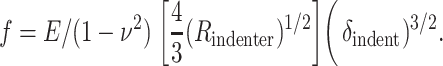 |
In comparison, for a cone of half-angle θ indenting a thick sample, Sneddon (1965) estimated
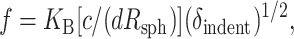
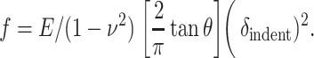 |
The latter is often found to provide the best fit of low force AFM experiments (f ∼ 200 pN or less) on cells, cell edges, and other soft samples (Domke and Radmacher, 1998; Radmacher, 1997; Radmacher et al., 1995; Rotsch et al., 1999; Rotsch and Radmacher, 2000).
One can arrive at similar expressions within the approximations of Eq. 4 in the text. We start by ignoring any pressure changes that would otherwise contribute to the force balance f ≈ σnet sin η pX, where σnet is the net membrane tension, η is the “wetting” angle with the horizontal that the membrane makes with the (constant θ) tip as it bends away (Fig. A1, A), and pX is the cross-sectional perimeter of the tip near that point: pX = 1/2(δindent ζtip). The adhesion-induced tension, σs, is supplemented by a linear dilation response to give σnet = σs + KA (ΔA / Ao), where KA ≈ 450 mN/m is the lipid bilayer dilation modulus (Evans et al., 1976) and ΔA is given by Eq. 4 in the text. Thus accounting for the adhesion-induced initial pre-stress σs, we arrive at a linear-plus-cubic relation for indentation force:
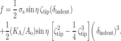 |
(A2) |
A purely linear force-displacement relation has been demonstrated by Evans et al. (1995) in their development of a micropipette-pressurized red cell as a biomembrane force probe. As long as the pressure-induced membrane tension (τm in their notation) exceeds the elastic shear modulus (∼0.01 mN/m) and stays constant (as does the intracellular pressure), the spring constant of the biomembrane force probe is set by membrane tension. There is also a geometric contribution from the size of the cell versus the size of a small bead attached diametrically opposite to the micropipette and used as the probing indenter. The linear term is expected to be valid (or dominant) for small indentations and forces. Once the intracellular pressure changes, σnet must increase and contribute to the second term above, although this may happen after a nonzero offset indentation (i.e., δindent + δoffset) rather than gauged from the initial contact point.
FIGURE A1.

Small force indentation behavior. (A) Schematic for indenting a prestressed membrane. (B) Indentation curve showing the hard limit as a dashed line at 1800 nm, and (C) low force behavior for three cells using the same tip (10 pN/nm). At the inflection with the baseline where membrane contact first appears, a line is fit with a slope of 0.2 ± 0.1 pN/nm (four cells).
An earlier computation (Evans and Skalak, 1980) of deformation of a spherical membrane by an attached spherical bead (radius = 0.1 Rsph) likewise demonstrated a linear force-extension relation under the constant tension assumption (and showed a constant “wetting angle”). Interestingly, a separate computation for a linearly dilatable membrane is also plotted (up to δindent ≈ 0.5Rsph), and an excellent fit can be obtained with a power law that can be written as
 |
Note the close similarities to the second term of Eq. A2, including the finding that the exponent, n = 2.66, is nearly cubic. Indeed, the previously cited differences between the Hertz model for a spherical indenter and the Sneddon model for a conical indenter further suggest n > 2.66.
Clearly the problem of AFM indentation in the center of an adhesively-tensed red cell has its potential complexities. While our principal interest in the present work is the high force behavior relevant to lysis and imaging, we have tried to do careful low force experiments with pico-Newton-stable baselines; such experiments are often problematic for soft AFM cantilevers mounted on an optical microscope as required here for proper placement of the tip. In analyzing small forces (<200 pN) and small indentations (<200 nm) for curves exhibiting maximum indentations within the error bars for cell height of Fig. 1 D, we often find a detectable inflection in the baseline that is followed by an initially linear force-indentation curve (Fig. A1, B and C). The slope of the linear fits is found to be 0.2 ± 0.1 pN/nm (four cells, same tip) with the variation possibly indicative of variable membrane tension. Solving for η in the linear term of Eq. A3 by using σs = 0.8 mN/m (see text), we arrive at η ≈ 15° (or π/12).
The nonlinear regimes of such indentation curves should introduce, if the above simple model is valid, a (δindent)3 term with a prefactor (KA / Ao) sin η ∼ 10−6. Best fits up to 3000 nN imply that the needed term is closer to (δindent)n with n ∼ 3.5, although multiterm polynomials suggested by the two-term sum (Eq. A2) also provide good fits. The difference with simple theory probably reflects a need for better account of the increasing pressure—conjugate to the cell volume constraint—as the AFM tip indents the sample.
APPENDIX 2 MAXIMUM FORCE APPLIED DURING TAPPING-MODE IMAGING
Distinct from the quasistatic force curves of Fig. 3 analyzed below, tapping-mode imaging reflects a more dynamic response to membrane indentations at the 100-pN/nm cantilever's resonant frequency in liquid (∼8000 Hz). Factoring in the raster velocity, for whole-cell imaging, each imaged pixel involves hundreds of contacts that progressively tap the membrane down from its spherical shape to its effective steric core. Since the tapping-mode free amplitude in liquid of this cantilever is ∼20 nm, we can estimate that the maximum possible force that can be exerted on the membrane by damping the amplitude of the cantilever is f ∼ 100 pN/nm × 20 nm = 2 nN.
Alina Hategan's permanent address is Electron Accelerator Lab, National Institute for Lasers, Plasma, and Radiation Physics, 76900 Magurele, Bucharest, Romania.
References
- Boal, D. 2002. Mechanics of the Cell. Cambridge University Press, Cambridge, UK.
- Bradow, S. L., D. C. Turner, B. R. Ratna, and B. P. Gaber. 1993. Modification of supported lipid membranes by atomic force microscopy. Biophys. J. 64:898–902. [DOI] [PMC free article] [PubMed] [Google Scholar]
- Brittain, J. E., K. J. Mlinar, C. S. Anderson, E. P. Orringer, and L. V. Parise. 2001. Activation of sickle red blood cell adhesion via integrin-associated protein/CD47-induced signal transduction. J. Clin. Invest. 107:1555–1562. [DOI] [PMC free article] [PubMed] [Google Scholar]
- Butt, H. J., E. K. Wolff, S. A. C. Gould, B. Dixon Northern, C. M. Peterson, and P. K. Hansma. 1990. Imaging cells with the atomic force microscope. J. Struct. Biol. 105:54–61. [DOI] [PubMed] [Google Scholar]
- Byers, T. J., and D. Branton. 1985. Visualization of the protein associations in the erythrocyte membrane cytoskeleton. Proc. Natl. Acad. Sci. USA. 82:6153–6157. [DOI] [PMC free article] [PubMed] [Google Scholar]
- Carl, P., C. H. Kwok, G. Manderson, D. W. Speicher, and D. E. Discher. 2001. Forced unfolding modulated by disulfide bonds in the Ig domains of a cell adhesion molecule. Proc. Natl. Acad. Sci. USA. 98:1565–1570. [DOI] [PMC free article] [PubMed] [Google Scholar]
- Chang, S. H., and P. S. Low. 2003. Identification of a critical ankyrin-binding loop on the cytoplasmic domain of erythrocyte membrane band 3 by crystal structure analysis and site-directed mutagenesis. J. Biol. Chem. 278:6879–6884. [DOI] [PubMed] [Google Scholar]
- Cheng, Y., M. Liu, R. Li, C. Wang, C. Bai, and K. Wang. 1999. Gadolinium induces domain and pore formation of human erythrocyte membrane: an atomic force microscopy study. Biochim. Biophys. Acta. 1421:249–260. [DOI] [PubMed] [Google Scholar]
- Clarke, M., G. Schatten, D. Mazia, and J. A. Spudich. 1975. Visualization of actin fibres associated with the cell membrane in amoebae of Dictyostellium discoideum. Proc. Natl. Acad. Sci. USA. 72:1758–1762. [DOI] [PMC free article] [PubMed] [Google Scholar]
- Czajkowski, D. M., H. Iwamoto, and Z. Shao. 2000. Atomic force microscopy in structural biology: from the subcellular to the submolecular. J. Electr. Microsc. 49:395–406. [DOI] [PubMed] [Google Scholar]
- Dai, J., M. P. Sheetz, X. Wan, and C. E. Morris. 1998. Membrane tension in swelling and shrinking molluscan neurons. J. Neurosci. 18:6681–6692. [DOI] [PMC free article] [PubMed] [Google Scholar]
- Discher, D. E., N. Mohandas, and E. A. Evans. 1994. Molecular maps of red cell deformation: hidden elasticity and in situ connectivity. Science. 266:1032–1035. [DOI] [PubMed] [Google Scholar]
- Discher, D. E., D. H. Boal, and S. K. Boey. 1998. Simulations of the erythrocyte cytoskeleton at large deformation. II. Micropipette aspiration. Biophys. J. 75:1584–1597. [DOI] [PMC free article] [PubMed] [Google Scholar]
- Domke, J., and M. Radmacher. 1998. Measuring the elastic properties of thin polymer films with the atomic force microscope. Langmuir. 14:3320–3325. [Google Scholar]
- Evans, E. A., R. Waugh, and L. Melnik. 1976. Elastic area compressibility modulus of red cell membrane. Biophys. J. 16:585–595. [DOI] [PMC free article] [PubMed] [Google Scholar]
- Evans, E. A., and R. Skalak. 1980. Mechanics and Thermodynamics of Biomembranes. CRC Press, Boca Raton, FL.
- Evans, E., K. Ritchie, and R. Merkel. 1995. Sensitive force technique to probe molecular adhesion and structural linkages at biological interfaces. Biophys. J. 68:2580–2587. [DOI] [PMC free article] [PubMed] [Google Scholar]
- Evans, E., and F. Ludwig. 2000. Dynamic strengths of molecular anchoring and material cohesion in fluid biomembranes. J. Phys. Condens. Matter. 12:A315–A320. [Google Scholar]
- Fain, S. C., K. A. Barry, M. G. Bush, B. Pettenger, and R. N. Louie. 2000. Measuring average tip-sample forces in intermittent-contact (tapping) force microscopy in air. Appl. Phys. Lett. 76:930–932. [Google Scholar]
- Fung, Y. C. 1993. Biomechanics. Mechanical Properties of Living Tissues. Springer Verlag, New York.
- Garcia, R., and A. San Paulo. 1999. Attractive and repulsive tip-sample interaction regimes in tapping-mode atomic force microscopy. Phys. Rev. B. 60:4961–4966. [DOI] [PMC free article] [PubMed] [Google Scholar]
- Garratty, G. 2001. Erythrophagocytosis on the peripheral blood smear and paroxysmal cold hemoglobinuria. Transfusion. 41:1073–1074. [DOI] [PubMed] [Google Scholar]
- Girasole, M., A. Cricenti, R. Generosi, A. Congiu-Castellano, G. Boumis, and G. Amiconi. 2001. Artificially induced unusual shape of erythrocytes: an atomic force microscopy study. J. Microsc. 204:46–52. [DOI] [PubMed] [Google Scholar]
- Haberle, W., J. K. H. Horber, and G. Binning. 1991. Force microscopy on living cells. J. Vac. Sci. Technol. B. 9:1210–1213. [Google Scholar]
- Heinrich, V., K. Ritchie, N. Mohandas, and E. Evans. 2001. Elastic thickness compressibility of the red cell membrane. Biophys. J. 81:1452–1463. [DOI] [PMC free article] [PubMed] [Google Scholar]
- Henderson, E., P. G. Haydon, and D. G. Sakaguchi. 1992. Actin filament dynamics in living glial cells imaged by atomic force microscopy. Science. 257:1944–1946. [DOI] [PubMed] [Google Scholar]
- Henon, S., G. Lenormand, A. Richet, J. Simeon, and F. Gallet. 1999. A new determination of the shear modulus of the human erythrocyte membrane using optical tweezers. Biophys. J. 76:1145–1151. [DOI] [PMC free article] [PubMed] [Google Scholar]
- Hertz, H. 1882. Uber die Beruhrung fester elastischer Korper. J. Reine Angew. Mathematik. 92:156–171. [Google Scholar]
- Hochmuth, R. M., and W. D. Marcus. 2002. Membrane tethers formed from blood cells with available area and determination of their adhesion energy. Biophys. J. 82:2964–2969. [DOI] [PMC free article] [PubMed] [Google Scholar]
- Hoh, J. H., and C. A. Schoenenberger. 1994. Surface morphology and mechanical properties of MDCK monolayers by atomic force microscopy. Biophys. J. 107:1105–1114. [DOI] [PubMed] [Google Scholar]
- Landau, L. D., and E. M. Lifshitz. 1959. Theory of Elasticity. Pergamon Press, London, UK.
- Le Grimellec, C., E. Lesniewska, M. K. Giocondi, E. Finot, and J. P. Goudonnet. 1997. Simultaneous imaging of the surface and the submembranous cytoskeleton in living cells by tapping mode atomic force microscopy. C. R. Acad. Sci. III. 320:637–643. [DOI] [PubMed] [Google Scholar]
- Le Grimellec, C., E. Lesniewska, M. C. Giocondi, E. Finot, V. Vie, and J. P. Goudonett. 1998. Imaging of the surface of living cells by low-force contact-mode atomic force microscopy. Biophys. J. 75:695–703. [DOI] [PMC free article] [PubMed] [Google Scholar]
- Lenormand, G., S. Henon, A. Richet, J. Simeon, and F. Gallet. 2001. Direct measurement of the area expansion and shear moduli of the human red blood cell membrane skeleton. Biophys. J. 81:43–56. [DOI] [PMC free article] [PubMed] [Google Scholar]
- Markle, D. R., E. A. Evans, and R. M. Hochmuth. 1983. Force relaxation and permanent deformation of erythrocyte membrane. Biophys. J. 42:91–98. [DOI] [PMC free article] [PubMed] [Google Scholar]
- Micic, M., A. Chen, R. M. Leblanc, and V. T. Moy. 1999. Scanning electron microscopy studies of protein-functionalized atomic force microscopy cantilever tips. Scanning. 21:394–397. [DOI] [PubMed] [Google Scholar]
- Mohandas, N., and E. A. Evans. 1994. Mechanical properties of the red cell membrane in relation to molecular structure and genetic defects. Annu. Rev. Biophys. Biomol. Struct. 23:787–818. [DOI] [PubMed] [Google Scholar]
- Muller, D. J., F. A. Schabert, G. Buldt, and A. Engel. 1995. Imaging purple membranes in aqueous solutions at sub-nanometer resolution by atomic force microscopy. Biophys. J. 68:1681–1686. [DOI] [PMC free article] [PubMed] [Google Scholar]
- Muller, D. J., D. Fotiadis, S. Scheuring, S. A. Muller, and A. Engel. 1999. Electrostatically balanced subnanometer imaging of biological specimens by atomic force microscope. Biophys. J. 76:1101–1111. [DOI] [PMC free article] [PubMed] [Google Scholar]
- Nagao, E., H. Nishijima, S. Akita, Y. Nakayama, and J. A. Dvorak. 2000. The cell biological application of carbon nanotube probes for atomic force microscopy: comparative studies of malaria-infected erythrocytes. J Electr. Microsc. 49:453–458. [DOI] [PubMed] [Google Scholar]
- Nermut, M. V. 1981. Visualization of the “membrane skeleton” in human erythrocytes by freeze-etching. Eur. J. Cell Biol. 25:265–271. [PubMed] [Google Scholar]
- Nowakowski, R., and P. Luckham. 2002. Imaging the surface details of red blood cells with atomic force microscopy. Surf. Inter. Anal. 33:118–121. [Google Scholar]
- Oldenborg, P. A., A. Zheleznyak, Y. F. Fang, C. F. Lagenaur, H. D. Gresham, and F. P. Lindberg. 2000. Role of CD47 as a marker of self on red blood cells. Science. 288:2051–2054. [DOI] [PubMed] [Google Scholar]
- Oesterhelt, F., D. Oesterhelt, M. Pfeiffer, A. Engel, H. E. Gaub, and D. J. Muller. 2000. Unfolding pathways of individual bacteriorhodopsins. Science. 288:143–146. [DOI] [PubMed] [Google Scholar]
- Ohta, Y., H. Okamoto, M. Kanno, and T. Okuda. 2002. Atomic force microscopic observation of mechanically traumatized erythrocytes. Artific. Organs. 26:10–17. [DOI] [PubMed] [Google Scholar]
- Radmacher, M., M. Fritz, and P. K. Hansma. 1995. Imaging soft samples with the atomic force microscope: gelatin in water and propanol. Biophys. J. 69:264–270. [DOI] [PMC free article] [PubMed] [Google Scholar]
- Radmacher, M. 1997. Measuring the elastic properties of biological samples with the AFM. IEEE Med. Biol. 16:47–57. [DOI] [PubMed] [Google Scholar]
- Raucher, D., and M. P. Sheetz. 1999. Characteristics of a membrane reservoir buffering membrane tension. Biophys. J. 77:1992–2002. [DOI] [PMC free article] [PubMed] [Google Scholar]
- Raucher, D., and M. P. Sheetz. 2000. Cell spreading and lamellipodial extension rate is regulated by membrane tension. J. Cell Biol. 148:127–136. [DOI] [PMC free article] [PubMed] [Google Scholar]
- Rief, M., M. Gautel, F. Oesterhelt, J. M. Fernandez, and H. E. Gaub. 1997. Reversible unfolding of individual titin immunoglobulin domains by AFM. Science. 276:1109–1112. [DOI] [PubMed] [Google Scholar]
- Rotsch, C., K. Jacobson, and M. Radmacher. 1999. Dimensional and mechanical dynamics of active and stable edges in motile fibroblasts investigated by using atomic force microscopy. Proc. Natl. Acad. Sci. USA. 96:921–926. [DOI] [PMC free article] [PubMed] [Google Scholar]
- Rotsch, C., and M. Radmacher. 2000. Drug-induced changes of cytoskeletal structure and mechanics in fibroblasts: an atomic force microscopy study. Biophys. J. 78:520–535. [DOI] [PMC free article] [PubMed] [Google Scholar]
- Sandre, O., L. Moreaux, and F. Brochard-Wyat. 1999. Dynamics of transient pores in stretched vesicles. Proc. Natl. Acad. Sci. USA. 96:10591–10596. [DOI] [PMC free article] [PubMed] [Google Scholar]
- San Paulo, A., and R. Garcia. 2000. High resolution imaging of antibodies by tapping mode atomic force microscopy: attractive and repulsive tip-sample interaction regimes. Biophys. J. 78:1599–1605. [DOI] [PMC free article] [PubMed] [Google Scholar]
- Seifert, U., and R. Lipowsky. 1990. Adhesion of vesicles. Phys. Rev. A. 42:4768–4771. [DOI] [PubMed] [Google Scholar]
- Scheffer, L., A. Bitler, E. Ben-Jacob, and R. Korenstein. 2001. Atomic force pulling: probing the local elasticity of the cell membrane. Eur. Biophys. J. 30:83–90. [DOI] [PubMed] [Google Scholar]
- Shao, J.-Y., and R. M. Hochmuth. 1999. Mechanical anchoring strength of L-selectin, 2 integrins, and CD45 to neutrophil cytoskeleton and membrane. Biophys. J. 77:587–596. [DOI] [PMC free article] [PubMed] [Google Scholar]
- Simson, R., E. Wallraf, J. Faix, J. Niewohner, G. Gerisch, and E. Sackmann. 1998. Membrane bending modulus and adhesion energy of wild-type and mutant cells of Dictyostelium lacking talin or cortexillins. Biophys. J. 74:514–522. [DOI] [PMC free article] [PubMed] [Google Scholar]
- Skalak, R., and S. Chien. 1987. Handbook of Bioengineering. McGraw-Hill Book Company, New York.
- Sneddon, I. N. 1965. The relation between load and penetration in the axisymmetric Boussinesq problem for a punch of arbitrary profile. Int. J. Eng. Sci. 3:47–57. [Google Scholar]
- Swihart, A. H., J. M. Mikrut, J. B. Ketterson, and R. C. Macdonald. 2001. Atomic force microscopy of the erythrocyte membrane skeleton. J. Microsc. 204:212–225. [DOI] [PubMed] [Google Scholar]
- Takeuchi, M., H. Miyamoto, Y. Sako, H. Komizu, and A. Kusumi. 1998. Structure of the erythrocyte membrane skeleton as observed by atomic force microscopy. Biophys. J. 74:2171–2183. [DOI] [PMC free article] [PubMed] [Google Scholar]
- Takev, K. D., J. K. Angarska, K. D. Danov, and P. A. Kralchevsky. 2000. Erythrocyte attachment to substrates: determination of membrane tension and adhesion energy. Coll. Surf. B Biointer. 19:61–80. [Google Scholar]
- Tuvia, S., A. Almagor, A. Bitler, S. Levin, R. Korenstein, and S. Yedgar. 1997. Cell membrane fluctuations are regulated by medium macroviscosity: evidence for a metabolic driving force. Proc. Natl. Acad. Sci. USA. 94:5045–5049. [DOI] [PMC free article] [PubMed] [Google Scholar]
- Waugh, R., and E. Evans. 1979. Thermoelasticity of red cell membrane. Biophys. J. 26:115–131. [DOI] [PMC free article] [PubMed] [Google Scholar]
- Willemsen, O. H., M. M. E. Snel, A. Cambi, J. Greve, and B. G. De Grooth. 2000. Biomolecular interactions measured by atomic force microscopy. Biophys. J. 79:3267–3281. [DOI] [PMC free article] [PubMed] [Google Scholar]
- Wolf, H., and D. Gingell. 1983. Conformational response of the glycocalyx to ionic strength and interaction with modified glass surfaces: study of live red cells by interferometry. J. Cell Sci. 63:101–112. [DOI] [PubMed] [Google Scholar]
- Wong, A. P., and J. T. Groves. 2002. Molecular topography imaging by intermembrane fluorescence resonance energy transfer. Proc. Natl. Acad. Sci. USA. 99:14147–14152. [DOI] [PMC free article] [PubMed] [Google Scholar]
- Yamashina, S., and O. Katsumata. 2000. Structural analysis of red blood cell membrane with an atomic force microscope. J. Electr. Microsc. 49:445–451. [DOI] [PubMed] [Google Scholar]
- You, H. X., J. M. Lau, S. Zhang, and L. Yu. 2000. Atomic force microscopy imaging of living cells: a preliminary study of the disruptive effect of the cantilever tip on cell morphology. Ultramicroscopy. 82:297–305. [DOI] [PubMed] [Google Scholar]
- Zachee, P., J. Snauwaert, P. Vandenberghe, L. Helemans, and M. Boogaerts. 1996. Imaging red blood cells with the atomic force microscope. Br. J. Haematol. 95:472–481. [DOI] [PubMed] [Google Scholar]
- Zhang, P. C., C. Bai, Y. M. Huang, H. Zhao, Y. Fang, N. X. Wang, and Q. Li. 1995. Atomic force microscopy study of fine structures of the entire surface of red blood cells. Scanning Microsc. 9:981–988. [PubMed] [Google Scholar]
- Zhang, Y., S. Sheng, and Z. Shao. 1996. Imaging biological structures with the cryo-atomic force microscope. Biophys. J. 71:2168–2176. [DOI] [PMC free article] [PubMed] [Google Scholar]
- Zhang, P., A. M. Keleshian, and F. Sachs. 2001. Voltage-induced membrane movement. Nature. 413:428–432. [DOI] [PubMed] [Google Scholar]