

Abstract
F1Fo-ATP synthase is a ubiquitous membrane protein complex that efficiently converts a cell's transmembrane proton gradient into chemical energy stored as ATP. The protein is made of two molecular motors, Fo and F1, which are coupled by a central stalk. The membrane unit, Fo, converts the transmembrane electrochemical potential into mechanical rotation of a rotor in Fo and the physically connected central stalk. Based on available data of individual components, we have built an all-atom model of Fo and investigated through molecular dynamics simulations and mathematical modeling the mechanism of torque generation in Fo. The mechanism that emerged generates the torque at the interface of the a- and c-subunits of Fo through side groups aSer-206, aArg-210, and aAsn-214 of the a-subunit and side groups cAsp-61 of the c-subunits. The mechanism couples protonation/deprotonation of two cAsp-61 side groups, juxtaposed to the a-subunit at any moment in time, to rotations of individual c-subunit helices as well as rotation of the entire c-subunit. The aArg-210 side group orients the cAsp-61 side groups and, thereby, establishes proton transfer via aSer-206 and aAsn-214 to proton half-channels, while preventing direct proton transfer between the half-channels. A mathematical model proves the feasibility of torque generation by the stated mechanism against loads typical during ATP synthesis; the essential model characteristics, e.g., helix and subunit rotation and associated friction constants, have been tested and furnished by steered molecular dynamics simulations.
INTRODUCTION
Efficient transformation of energy into synthesis of adenosine triphosphate (ATP) is vital for living cells. The ubiquitous enzyme that uses the transmembrane electrochemical potential to synthesize ATP in bacteria, chloroplasts, and mitochondria is F1Fo-ATP synthase, a complex of two molecular motors, Fo and F1 (see Fig. 1), mechanically coupled by a common central stalk. The membrane-embedded Fo unit efficiently converts the proton-motive force into mechanical rotation of the central stalk inside the solvent-exposed F1 unit. The rotation causes cyclic conformational changes in F1, thereby driving ATP synthesis (Boyer, 2000). The enzyme can also function in the reverse direction, hydrolyzing ATP and utilizing the released energy to pump protons across the membrane.
FIGURE 1.

Schematic view of the E. coli ATP synthase. The solvent-exposed F1 unit (top) consists of subunits α3β3γδɛ; the membrane Fo unit (bottom) consists of subunits ab2c10.
F1Fo-ATP synthase structure and function are essentially conserved among most species, suggesting common mechanisms of proton translocation and ATP synthesis or hydrolysis (Senior, 1988; Dmitriev et al., 1999; Rastogi and Girvin, 1999; Groth, 2000; Kaim, 2001; Jiang et al., 2001; Stock et al., 1999; Seelert et al., 2000; Vonck et al., 2002; Abrahams et al., 1994). Fig. 1 provides a schematic view of ATP synthase from Escherichia coli, which has a relatively simple structure. The Fo motor is made of three different polypeptides: subunit a, which is assumed to mediate proton translocation across the membrane; a dimer of subunits b, which mechanically connects the Fo and F1 motors; and a cylindrical cn oligomer of c-subunits (Dmitriev et al., 1999; Rastogi and Girvin, 1999; Groth, 2000; Kaim, 2001). In E. coli, the number, n, of c-subunits was found to be 10 (Jiang et al., 2001); in other species, it may vary from 10 to 14 (Stock et al., 1999; Seelert et al., 2000; Vonck et al., 2002).
Here, we report molecular dynamics simulations and mathematical modeling of the Fo motor, which couples proton translocation across the membrane with mechanical rotation of the c10 oligomer relative to the ab2 complex (Sambongi et al., 1999; Pänke et al., 2000; Tanabe et al., 2001; Junge et al., 2001). Site-directed mutagenesis experiments have identified two residues to be critical for Fo operation (Valiyaveetil and Fillingame, 1997; Fillingame et al., 2002): aArg-210 in one of the transmembrane α-helices (TMH), TMH4, of the a-subunit and cAsp-61 in the outer TMH of each c-subunit, the primary proton binding sites (see Fig. 2) located in the middle of the membrane hydrophobic layer (Fillingame et al., 2002). Each cAsp-61 can assume either a protonated (neutral) or deprotonated (negatively charged) state. Since the membrane-spanning domains of the c-subunits are formed almost entirely by hydrophobic residues, which cannot mediate proton translocation, the binding sites can only change their protonation states when in contact with the a-subunit. The latter includes polar groups, which are thought to form two proton half-channels terminated by residues aSer-206 and aAsn-214 of the a-subunit (Fillingame et al., 2002; Angevine and Fillingame, 2003), as shown in Fig. 2. The inlet half-channel ending at aAsn-214 connects the proton-rich periplasm to a domain located in the middle of the hydrophobic membrane layer; the outlet half-channel beginning at aSer-206 connects this domain to the cytoplasm. To allow rotation of the c10 complex, a cAsp-61 binding site needs to be protonated before leaving the interface to avoid energetically unfavorable exposure of an electrically charged residue to the hydrophobic membrane environment. This is achieved by a proton traveling from the periplasm via the inlet half-channel and protonating the cAsp-61 binding sites. The rotation of the c10 oligomer, induced by the proton electrochemical gradient, after an almost complete revolution, brings the binding sites close to the a-subunit again, causing it to release a proton, which then travels to the cytoplasm via the outlet half-channel.
FIGURE 2.

Microscopic model of Fo ATPase composed of a four-helix bundle (a2–a5) of subunit a and an oligomer of 10 c-subunits. Only backbones of subunit a and of one out of 10 cTMH-2 (c2R) are shown as tubes; the rest of the c10 oligomer's helices are shown as cylinders. The binding sites (cAsp-61) of the c10 oligomer, the termini of the proton half-channels (aSer-204 and aAsn-214), and the critical aArg-210 residues of subunit a are drawn in van der Waals representation. The interface between a- and c-subunits was modeled.
Although the rotary catalysis mechanism (Boyer, 1997) has been recently demonstrated in a series of spectacular single molecule experiments for both the F1 (Yasuda et al., 2001; Kato-Yamada et al., 1998; Noji et al., 1997, 1999; Masaike et al., 2000; Hirono-Hara et al., 2001) and the Fo units (Sambongi et al., 1999; Pänke et al., 2000; Tanabe et al., 2001; Junge et al., 2001), the understanding of the involved atomic scale events in Fo is still limited. For the F1 unit, several high resolution structures have been obtained (Abrahams et al., 1994; Menz et al., 2001; Gibbons et al., 2000), setting the stage for the first all-atom steered molecular dynamics (MD) investigations of functionally relevant domain motions involved in ATP synthesis and hydrolysis (Böckmann and Grubmüller, 2002; Ma et al., 2002). For the Fo unit, no complete atomistic structure is available yet. However, a number of structural models based on NMR experiments, disulfide cross-linking data, scanning mutagenesis, and analysis of suppressor mutations have emerged (Dmitriev et al., 1999; Rastogi and Girvin, 1999; Groth, 2000; Girvin et al., 1998; Jones et al., 1998; Jiang and Fillingame, 1998; Fillingame et al., 2000b), that may be integrated into a full atomic scale structure.
NMR and cross-linking experiments indicated, in particular, that the position of cAsp-61 depends on its protonation: in the protonated state, cAsp-61 is hidden inside the hydrophobic core of the c-unit (Dmitriev et al., 1999; Rastogi and Girvin, 1999; Girvin et al., 1998), whereas in the deprotonated state it extends to the outside (Rastogi and Girvin, 1999). A large rotation of the outer TMH of a c-subunit around its axis is necessary to bring cAsp-61 to the interface with the a-subunit, where it can bind as well as release a proton.
Although rotation of individual TMHs successfully explains the observed conformational changes in the c-subunit upon protonation or deprotonation of cAsp-61, a number of questions still remain to be answered. How are rotations of individual TMHs coupled to each other and to rotation of the c10 oligomer? How does rotation depend on the protonation states of cAsp-61 residues? In particular, since deprotonated cAsp-61 is likely to form a salt bridge with aArg-210, how is relative motion between the a-subunit and the c-subunit possible? Answers to these questions may reveal the motor mechanism.
To explore Fo on the atomic scale, we combine mathematical modeling with all-atom MD simulations of the E. coli protein in its native environment (membrane and water). The gap between the timescales of processes that need to be described makes a twofold approach imperative: under physiological conditions, the elementary protonation/deprotonation events as well as the subsequent structural relaxation occurs on the picosecond timescale whereas the central stalk rotation requires milliseconds. We bridge the timescales by combining a mathematical model of the overall millisecond function of Fo with nanosecond MD simulations. The model assumes that the Fo motor operates as a molecular ratchet, in which the proton-motive force biases the rotational diffusion of the c-oligomer (Junge et al., 1997) and is described as suggested in Mogilner et al. (2002). The MD simulations test the feasibility of the model and determine some of the model's parameters. Unlike the one-dimensional ratchet model proposed in Elston et al. (1998), which describes a generic molecular motor, our model is directly related to the atomistic structure and dynamics of the Fo unit.
METHODS
The Fo motor was investigated by MD simulations carried out after modeling the E. coli Fo structure shown in Fig. 2. The MD simulations provided the bases for the stochastic model sketched in Fig. 4.
FIGURE 4.

Stochastic model for Fo (view from cytoplasm). Four out of 10 c-subunits and the a-subunit are shown. The c10 complex is fixed, and the a-subunit can move in either direction (angle θa). This is equivalent to the more natural choice of a fixed subunit a and a moving c10 complex. The second transmembrane helix (c2) of each c-subunit can rotate independently (described by angles θ1, θ2, θ3, and θ4), thereby moving the key cAsp-61 residues, which are the proton-binding sites. The c1 helices do not rotate. Similarly, only the fourth helix of the a-subunit (a4) can rotate (angle θR), moving the aArg-210 residue; helices a2, a3, and a5 do not rotate. Proton transfer occurs between the terminal residue of the periplasmic channel (aAsn-214) and the cAsp-61 binding site on helix c2R, and between the terminal residue of the cytoplasmic channel (aSer-206) and the cAsp-61 binding site on c2L. Motions are confined to the plane of the figure. The system is fully described by helix orientations θ1, θ2, θ3, and θ4 (c-subunits), θR (a4), rotor angle θa, and protonation state of the two aspartates (cAsp-61) on helices c2L and c2R.
Structure building
Presently, there is no structure available for the Fo sector of the ATP synthase that encompasses the c10 oligomer and the a-subunit (see Fig. 1). The only available crystallographic structure is one for the mitochondrial F1-c10 complex, at 3.9 Å resolution (Stock et al., 1999), that does not include subunit a critical for ATPase function. Several structural models for components of Fo (including a model for subunit a) have been developed on the basis of disulfide cross-linking data and NMR experiments performed in polar solvents and detergents (Dmitriev et al., 1999; Jones et al., 1998; Rastogi and Girvin, 1999; Groth, 2000; Girvin et al., 1998). It is not clear, however, in how far the protein structure in detergent is similar to that in membranes (Groth, 2000), and to which extent the proposed models are accurate. To model the function of Fo at atomic resolution, a structural model of Fo in its native environment needed to be constructed first. For this purpose we merged previously suggested models of Fo components. We note here that the model used and, hence, also our own model, still involve great uncertainties.
The structure shown in Fig. 2 was obtained starting from the a1c12 complex (PDB code 1c17, Rastogi and Girvin, 1999), which includes four of the five TMHs of subunit a. The c12 oligomer was then replaced by the c10 oligomer (PDB code 1c0v; Dmitriev et al., 1999; Stock et al., 1999; Fillingame et al., 2000b). Since neither a specific role in proton translocation has been ascribed to the b-subunits, nor their exact position yet determined (Dunn et al., 2000), subunits b were disregarded.
To obtain a correct interface between the a- and c-subunits, we carried out 10,000 steps of conjugate gradient minimization followed by 130 ps of equilibration in vacuum at 4 K with the backbone atoms of all c-subunits restrained. The low temperature assured that no significant change in dihedral angles (and, therefore, in the protein conformation) could occur, whereas the equilibration substantially improved the alignment of the a-subunit TMHs to the c-subunits at the interface. The distance between the centers of mass (computed using coordinates of the backbone α-carbons) of the c10 complex and the a-subunit shrank from 39.4 Å to 38.0 Å. The alignment occurred within the first 70 ps of equilibration, and no structural changes were observed afterward. The alignment process is illustrated by supplied movies at http://www.ks.uiuc.edu/Research/f0atpase/movies/.
The resulting protein structure was embedded into a square patch of a phosphatidylethanolamine membrane. The membrane structure was obtained by generating a lipid bilayer, either layer of which was built by placing lipid molecules onto the nodes of a hexagonal lattice. The lattice vectors were chosen to reproduce the surface area per lipid of 57 Å2, the value observed in experiments. Each lipid molecule was randomly rotated in the membrane plane, and its position in the direction normal to the plane was randomly shifted. The lipid headgroups were solvated using the Solvate program (Grubmüller et al., 1996). The protein was embedded into the membrane using the available disulfide cross-linking data, and all lipid molecules that overlapped with the protein were removed. Two lipid molecules at either side were left in the central cavity of the protein.
The protein-lipid complex was then solvated in a rectangular volume of preequilibrated TIP3 water molecules. Sodium and chlorine ions were added, corresponding to an ionic strength of 0.05 mM. The final system (Fig. 2) measured 112 × 123 × 98 Å3 in size and included 111,714 atoms.
We performed 700 steps of minimization followed by gradual heating from 0 to 310 K in 2 ps, equilibration for 2.75 ns with the backbone protein atoms constrained, and equilibration for another 1.9 ns without constraints. The protein structure was closely monitored during the equilibration. Within the first 1.3 ns of the unrestrained equilibration the center of mass of the a-subunit drifted by 1.5 Å in the direction normal to the membrane. The distance between the c10 complex and the a-subunit did not change. In the last 0.6 ns of the equilibration the a-subunit position remained unchanged. After the equilibration, the root-mean square deviation (RMSD) of the α-carbon atoms from the initial structure reached 2.7 Å. To find out which protein domains are most different from the initial structure, the RMSD was computed separately for different protein parts; the results of the calculations are shown in Fig. 3. The RMSD of all protein atoms located within the lipid bilayer reached a stationary value of 1.6 Å in 1.3 ns and did not increase significantly thereafter. In contrast, the RMSD of the solvent-exposed residues of the c10 oligomer (residues 1–6, 38–49, and 74–79) steadily increased throughout the equilibration, reaching 4 Å at the end. The origin of this increase was spontaneous unwinding of the solvent-exposed parts of the c-subunit α-helices. Thus, the transmembrane part of the protein structure proved to be stable and suitable for MD simulations. In all other simulations of the Fo unit the backbone atoms of the solvent-exposed parts of the c-subunits were restrained.
FIGURE 3.

RMSD values of the a1c10 complex α-carbon atoms during the equilibration.
Molecular dynamics simulations
The MD simulations were performed using the NAMD2 program (Kalé et al., 1999), CHARMM27 force field (MacKerell et al., 1998), periodic boundary conditions, and particle mesh Ewald full electrostatics (Batcho et al., 2001). The temperature was kept at 310 K by either applying Langevin forces (Brünger, 1992) to all heavy atoms or velocity-rescaling every 25–50 ps. The integration time step chosen was 1 fs. The equilibration was performed in the NpT ensemble using the Nosé-Hoover Langevin piston pressure control (Martyna et al., 1994). Van der Waals energies were calculated using a smooth (10–12 Å) cutoff.
Since the timescale of large MD simulations is currently limited to ∼10 ns, steering forces were applied to speed up the relevant protein domain motions. Steered MD simulations (Isralewitz et al., 2001a,b; Park et al., 2003) were performed in the NVT ensemble, using the NAMD2 Tcl interface. To avoid distortion of the protein structure, steering forces were applied to all backbone atoms of rotating protein domains, with a force magnitude proportional to the distance atom-rotation axis. Since the density of atoms across the lipid bilayer varies, the steering forces were scaled proportional to the atom density to achieve more uniform rotation. To control system temperature, dissipate heat generated by forces applied, and stabilize the protein structure, Langevin forces acted on all heavy atoms.
Stochastic model
Our model, based on the atomistic structure of Fo in the lipid-solvent environment, reduces the overall dynamics to a few essential degrees of freedom. We assume that all torque-generating events occur at the interface between the a-subunit and the c10 oligomer, and, therefore, use as effective coordinates 1), the rotation angle of the c10 oligomer relative to the a-subunit (angle θa); 2), rotation of aTMH4 that hosts the critical aArg-210 residue (angle θR); and 3), rotation angle of the four c2 helices near the a-subunit that host the critical cAsp-61 residues (angles θ1, θ2, θ3, and θ4). The model geometry is defined in Fig. 4.
Out of the 10 subunits in the c-oligomer, only two (c2L and c2R in Fig. 4) form, with their c2 helices, a contact with the a-subunit. Our model includes these two helices as well as the two adjacent c2 helices (c2′L and c2′R) needed to account for the periodicity of the c10 oligomer. Each c2 helix is described by one rotation angle defined through the orientation of the helix's critical residue, the latter represented by a zero or negative charge located at a fixed distance from the helix axis. The model also accounts for the protonation states of the c2L and c2R cAsp-61 residues; the residues are negatively charged in the deprotonated state and electrically neutral in the protonated state; the aArg-210 residue is always positively charged. Protonation or deprotonation of either cAsp-61 residue can only occur when it approaches the terminal residue of either the periplasmic (aAsn2-14) or the cytoplasmic (aSer-206) proton half-channel (see Fig. 2). The atomistic structure of the half-channels is incorporated in the model by specifying explicitly the proton path to each binding site.
Our model was formulated relative to the c10 complex coordinate frame (see Fig. 4). The position of the a-subunit relative to the c10 complex is described by the angle θa, which becomes zero when a4 is equidistant to the two c2 helices nearest to it. The periodic property
 |
(1) |
was assumed, where f denotes any function dependent on θa. When a4 passes by c2R(θa > π/10), the following cyclic replacement of the variables takes place: c2L′ → c2R′; c2L → c2L′; c2R → c2L; and c2R′ → c2R. On the other hand, when a4 passes by c2L (θa < −π/10), the cyclic replacement of the variables takes place in the reverse direction: {c2L′, c2L, c2R, c2R′} → {c2L, c2R, c2R′, c2L′}. Helices c2L′ and c2R′ were introduced in the model solely to provide this specific type of boundary condition. They do not participate in any interactions with subunit a, nor can they change their protonation states. The helices do, however, perform stochastic rotary motions, and they are influenced by the potential of mean force (PMF) just as the other c2 helices are.
Mechanical motion in the protein complex is described by a system of Langevin equations,
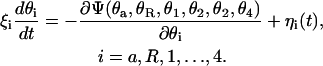 |
(2) |
The timescale for the rotary motion of the helices and the c10 oligomer is determined by the friction coefficients, ξi, which are related to the average magnitude of the corresponding random forces, ηi, through the fluctuation-dissipation theorem,
 |
(3) |
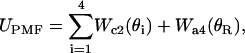
The potential function Ψ in Eq. 2 is a sum of all potential energy terms,
 |
(4) |
Here UNB describes the nonbonded interactions between the binding sites and aArg-210,
 |
(5) |
UH describes the hydrophobic interaction of the binding sites with the lipid bilayer,
 |
(6) |
and UPMF accounts for the PMF acting on the individual helices,
 |
(7) |
where  ,
,  , and
, and  denote positions of the key residues on c2L, c2R, and a4 helices, respectively, and
  denotes the a4 helix position. The load torque τ imposed by the F1 unit acts on θa only. The motor operates against this load, driving thereby synthesis of ATP.
Charged residues interact according to a screened electrostatic potential (Dimroth et al., 1999),
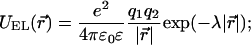 |
(8) |
here q1 and q2 are the charges of the residues, ɛ is the dielectric constant of the protein environment, 1/λ is the Debye screening length, and we assumed e2/(4πɛ0) ≈ 56 kBT nm (other parameters are listed in Table 1). To prevent the residues from getting too close to each other, the repulsive part of the Lennard-Jones potential,
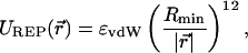 |
(9) |
was included in the nonbonded potential energy term. The Rmin parameter in Eq. 9 specifies the size of the particle representing the residue. Values for ɛvdW and Rmin parameters were based on the CHARMM force field (MacKerell et al., 1998).
TABLE 1.
The parameters of the stochastic model of Fo function
| Parameter | Notation | Value | Origin |
|---|---|---|---|
| cTMH2–c10 distance | RcTMH2 | 2.26 nm | MD |
| cTMH2–cAsp-61 charge distance | A | 0.4 nm | MD |
| aTMH4–aArg-210 charge distance | B | 0.6 nm | MD |
| aTMH4–c10 distance | RaTMH4 | 2.98 nm | MD |
| Helix rotary diffusion coefficient | Dhelix | 2 × 10⁵ s−1 | MD, Elston et al. (1998) |
| c10 complex rotary diffusion coefficient | Dc10 | 2 × 10⁴ s−1 | MD, Elston et al. (1998) |
| Steepness coefficient of hydrophobic potential H, Eq. 10 | S | 2 | Ad hoc |
| Extent of hydrophobic potential H, Eq. 10 | D | 1.25 nm | Ad hoc |
Steepness coefficient of hydrophobic potential  Eq. 20 Eq. 20
|
 |
20 | Ad hoc |
| Fo dielectric constant, Eq. 8 | ɛ | 10 | Elston et al. (1998) |
| Shielding length, Eq. 8 | 1/λ | 1.1 nm | Elston et al. (1998) |
| vdW interaction energy parameter, Eq. 9 | ɛvdW | 0.04 kBT | CHARMM |
| Virtual ion diameter, Eq. 9 | Rmin | 0.3 nm | CHARMM |
| pKa of cAsp-61 | pKa | 5.0 | Maximum ATP synthesis rate |
| Bulk pH for the periplasm | PH(peri) | 7 | Elston et al. (1998) |
| Bulk pH for the cytoplasm | PH(cyto) | 8.4 | Elston et al. (1998) |
| Surface potential at the periplasmic side of the membrane | Δφ(peri) | 2.3 kBT | Elston et al. (1998) |
| Surface potential at the cytoplasmic side of the membrane | Δφ(cyto) | 2.3 kBT | Elston et al. (1998) |
| Membrane potential | Δψ | 5.6 kBT | Elston et al. (1998) |
| Channel absorption rate of H+, Eq. 15 | σ | 1.86 × 10¹⁰ nm3/s | Elston et al. (1998) |
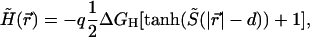
It was estimated that exposing a deprotonated aspartate to the hydrophobic environment of a lipid bilayer would cause a free energy penalty of ∼45 kBT (Elston et al., 1998). Accordingly, the hydrophobic interactions would prevent a deprotonated cAsp-61 from leaving the vicinity of the a-subunit. In the model, an empirical function was introduced to account for this effect. A smoothed step function,
 |
(10) |
was chosen, which allows us to precisely define a range d and a magnitude S of the interaction. The distance  between cAsp-61 and a4 controlled H. The free energy penalty in Eq. 10 is specified by ΔGH; q is the charge of cAsp-61.
The influence of the helix environment was taken into account by specifying a PMF for each helix type considered, Wc2 for c2 and Wa4 for a4. It was assumed that the PMF of each helix is a function of that helix's orientation only, independent of the other helices' conformations. All numerical calculations reported in this article employed empirical potentials of mean force acting on helices c2 and a4 reproduced in Fig. 5. It is possible, in principle, to compute these PMFs directly from microscopic simulations using a method described in Jensen et al. (2002).
FIGURE 5.

Potentials of mean force used in the stochastic simulations: a double-well potential governing rotation of the c2 helices (open squares) and a parabolic potential governing rotation of the a4 helix (open circles).
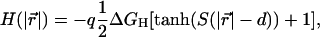
The change of the cAsp-61 protonation state is described as a Markov process, the rate constants of which depend on the distances between the relevant side groups and, thus, on the angles θa, θR, θ2, and θ3. Our description of the proton transfer events was adapted from an earlier model (Elston et al., 1998). The chemical reaction on the H+ binding sites is represented by
 |
(11) |
At equilibrium,
 |
(12) |
where kin and kout are the proton hopping rates to and off the binding site, and the square brackets indicate concentration. Given the definition,
 |
(13) |
the hopping rates obey the relation
 |
(14) |
In our model, only two cAsp-61 residues can participate in the proton transfer reaction at a time. Those are the residues that are in contact with either the periplasmic or the cytoplasmic channel. The proton pathways to and from the binding sites are not known yet. It was suggested that the residues involved in the proton transfer are located along the a4 helix (Fillingame et al., 2002; Angevine and Fillingame, 2003). Through MD simulations, which are described in Results and Discussion, we found that by turning the c2 helix, the binding sites can be exposed to either aAsn-214 or aSer-206 residues (which belong to the a4 helix; see Figs. 2 and 7). A positively charged aArg-210, which is located between aAsn-214 and aSer-206, prohibits a direct proton transfer between these residues, thereby directing the proton current to and from the binding sites. To incorporate this information into our model, it was postulated that, at any time, the binding site at c2L is accessible only from the cytoplasm and the binding cite at c2R is accessible only from the periplasm. Also, the proton transfer was assumed not to be possible when the binding sites are distant from the a4 helix.
FIGURE 7.

Hydrogen-bond network formed between the binding sites (cAsp-61) and the terminal residues of the proton periplasm (aAsn-214) and cytoplasm (aSer-206) channels. The critical residue aArg-210 forms transient hydrogen bonds with both binding sites.
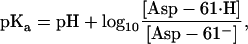
The rate kin is limited by the rate of proton influx into the channel. It can be computed by the Smoluchowski formula (Berg, 1983),
 |
(15) |
where [H+]surf is a surface proton concentration and σ is an absorption rate of the channel. Surface charges on the membrane can modify the surface proton concentration, thereby changing the electric potential drop across the membrane. The latter has no influence on kin, but kout depends on the potential drop. The proton hopping rates are also affected by the electrostatic potential generated by the charged residues. The rates were calculated using the following formulae:
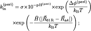 |
(16) |
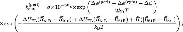 |
(17) |
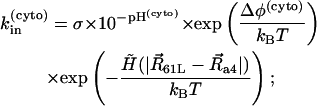 |
(18) |
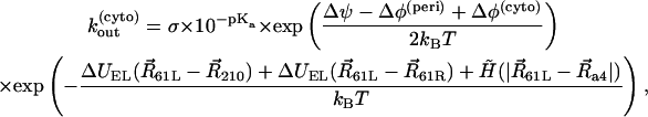 |
(19) |
where Δφ(peri) and Δφ(cyto) are potential drops induced by the surface charges at the periplasmic and cytoplasmic sides, respectively, Δψ is a membrane potential, and ΔUEL measures the difference of the electrostatic potential of cAsp-61 after its deprotonation. A hydrophobic potential,
 |
(20) |
was introduced in Eqs. 16–19 to prevent cAsp-61 from deprotonation (or protonation) when it is located far from a4. A strong distance dependence of the proton transfer probability was introduced by the steepness,  of the potential.
Unlike the one-dimensional ratchet model in Elston et al. (1998), which describes a generic protein motor, our approach directly relates the atomistic structure and dynamics of the Fo unit to the stochastic model. All geometrical parameters were determined by analyzing a 1-ns all-atom MD simulation of Fo; in particular, the particle models for cAsp-61 and aArg-210 were developed by computing the average distances from the residue charge center to the center of the parent helix. The atomistic structure of the half-channels was incorporated in the model by explicitly specifying the proton path to each binding site. Steered MD simulations (Isralewitz et al., 2001b) were performed to show that the cAsp-61 binding sites are accessible to proton transfer from the terminal residues of the half-channels (Fig. 7). The friction coefficients, ξi, were estimated by simulating a forced rotation of the individual transmembrane helices and of the c10 complex, as described in Results and Discussion (see also supplied movies at http://www.ks.uiuc.edu/Research/f0atpase/movies/).
All of the parameters used for the numerical analysis are listed in Table 1. To make comparison with the earlier model easier, some parameters were adapted from Elston et al. (1998).
To describe the dynamics of the Fo unit at the millisecond timescale, the system of stochastic differential equations (Eq. 2) was solved by numerical integration over time under the cyclic boundary conditions. Simultaneously, chemical reaction (Eq. 11) at two binding sites was simulated as a Markov process with the rate constants given by Eqs. 16– 19. The time step used in all simulation was 10−10 s. The random forces were generated in accordance with Eq. 3. The Fokker-Planck formulation, that was used to analyze numerically the earlier one-dimensional model (Elston et al., 1998), becomes computationally very expensive in the case of the present multidimensional system. Hence, our numerical solution relied on integrating the Langevin equations. To obtain statistically averaged data, a large number of independent runs were performed.
Our model includes several critical approximations. Most importantly, we considered an essentially two-dimensional system, assuming all key residues to be located in a plane and neglecting the residues' flexibility. This assumption results in a rather high sensitivity of the model to the parameters used. The total PMF was assumed to be a sum of independent contributions for each helix (Fig. 5). Empirical functions were used to model the PMF and to account for hydrophobic effects. Although our model utilizes most of the available atomistic structural information on the Fo motor, a more rigorous description will require additional structural data, particularly on the a-/c10-subunit interface.
RESULTS AND DISCUSSION
The key events involved in Fo function include rotation of the c10 oligomer relative to the a-subunit, rotation of individual TMHs in the a- and c-subunits, and protonation and deprotonation of the proton binding sites (Rastogi and Girvin, 1999; Fillingame et al., 2002; Elston et al., 1998). Below we discuss how these events are coupled to one another and how they control the system dynamics on the physiological timescale. Fig. 6 depicts the series of events involved in a 2π/10 rotation of the c10 oligomer. This figure serves to better illustrate our model of Fo function; as discussed at the end of the article, the figure presents actually a main result of our study, rather than an a priori model. The MD simulations described in this section are illustrated by animations available as supporting information at http://www.ks.uiuc.edu/Research/f0atpase/movies/.
FIGURE 6.

Schematic representation of the sequence of events suggested by our study. These events, labeled a–f, occur during rotation of the c10 oligomer by 2π/10 in the synthesis direction, viewed here from the cytoplasm. (a) In the starting conformation, two residues cAsp-61 are deprotonated and form a bidentate salt bridge with aArg-210, cAsp-61−–aArg-210–cAsp-61−. (b) A proton is transferred from the terminal residue of the periplasmic proton channel, aAsn-214, to cAsp-61 on helix c2R. (c) Subunit a rotates clockwise with respect to the c10 oligomer in concert with a clockwise rotation of helix c2L. When subunit a approaches helix c2L′, cAsp-61 on that helix rotates by 180°. The latter rotation may proceed in either clockwise or counterclockwise direction. (d) The concerted rotation of subunit a and helix c2L are completed: cAsp-61 on helix c2L′ has rotated by 180° toward subunit a. (e) A proton is transferred to the terminal residue of the cytoplasmic proton channel, aSer-206. (f) The system returns to the starting conformation a, but with the c10 oligomer advanced by an angle 2π/10. We note that the processes depicted are of stochastic nature, and, hence, do not necessarily obey the strict sequence shown.
Rotation of the c10 oligomer relative to subunit a
The forced rotation of the c10 oligomer was simulated for applied torques between 500 and 10,500 kcal/mol. cAsp-61 in all c-subunits were kept protonated. To prevent subunit a from being dragged along with the c-subunits and the surrounding lipid molecules, all backbone atoms of transmembrane α-helices 2, 3, and 5 of subunit a were restrained. Only TMH4 of subunit a, which forms the interface with the c-subunits, was not restrained. The rotation axis was normal to the membrane plane and located at the center of mass of the c10 oligomer. Simulation times varied from 0.1 to 10 ns depending on the applied torque. In all simulations, the protein structure remained stable and the final rotation angle exceeded 2π/10. For torques of <∼1000 kcal/mol, the angular velocity was approximately proportional to the applied torque, suggesting a constant friction regime. For higher torques, the angular velocity increased faster than the applied torque.
Rotation of individual TMHs
As suggested by Rastogi and Girvin (1999) as well as Fillingame and co-workers (Fillingame et al., 2002, 2000a; Jiang and Fillingame, 1998) rotation of the outer TMH of the c-subunits is a key step in the mechanism of Fo operation. This rotation was simulated by harmonically constraining each heavy atom of the outer TMH of the c-subunits to a reference point, which was rotating with a constant angular velocity. The rotation axis was the principal axis of the largest moment of inertia of the helix. Rotations were enforced at several angular velocities. The total torque exerted on the helix was monitored. The average torque required to rotate the helix increased with the angular velocity but, at small velocities (0.5–2 revolutions per nanosecond), was almost constant (∼175 kcal/M). The constant average torque regime is due to a kink induced by cPro-64 in the outer TMH, which causes steric collisions between the TMH and the surrounding protein and lipids when the TMH is rotated as a whole. However, the TMH conformation remains unchanged, since the steered atom trajectories follow a rotating template of the same shape as the initial helix.
To investigate the feasibility of TMH rotation at smaller applied torques, we simulated a system with one c-subunit embedded in a lipid bilayer and surrounded by water and ions. The forces were applied to all backbone atoms of the outer TMH, whereas the backbone atoms of the inner TMH were restrained. The proton binding site (cAsp-61) was kept protonated. To minimize steric hindrance, each residue was rotated around an individual axis directed along the local center line of the helix. The TMH thus rotated entirely within its reptation tube formed by the surrounding atoms. Not exactly being a rotation, this motion resulted in minor changes of the helix conformation and reduced the friction with the surrounding lipids. The angular velocity fluctuated in time, with occasional halts. Rotations were induced for both clockwise and counterclockwise directions, and no preference was observed. Interestingly, the average angular velocity was different for the TMH parts on either side of the cPro-64 kink: residues 47–63 tended to move faster than residues 64–79. Rotation at ∼15°/ns required a torque of ∼60 kcal/mol. Friction coefficients determined from these simulations were utilized in the stochastic model.
Proton access to the binding sites
As shown in Fig. 2, the suggested terminal residues of the half-channels (Fillingame et al., 2002; Angevine and Fillingame, 2003) are located close to aArg-210. Since the outer TMH of the c-subunits forms an angle of ∼17° with the inner TMH, rotation of the former moves cAsp-61 in the direction across the membrane, thereby bringing the side group closer to either proton half-channel terminus: in the model depicted here (Fig. 2), cAsp-61 is close to aAsn-214 at the periplasmic half-channel terminus; rotating the outer TMH by 180° brings cAsp-61 closer to the cytoplasmic side by ∼3 Å (Fig. 7). Therefore, rotation of the outer TMH can switch accessibility of the proton binding site from the periplasm to the cytoplasm and back (see also Fig. 6). The position of aAsn-214 is supported by the aN214C/cM65C cross-link (Jiang and Fillingame, 1998).
To further investigate proton access to the cAsp-61 binding sites, rotations of the c2L helix (see Fig. 8) by ∼180° were induced. Initially, cAsp-61 at both c2L and c2R were protonated. After cAsp-61 at c2L was deprotonated, it formed a stable hydrogen bond with aSer-206, the terminal group of the cytoplasmic channel (see Fig. 2). Next, helices c2L and c2R and the c10 oligomer were rotated by small angles, modeling microsecond rotational diffusion. Eventually, another stable hydrogen bond was formed between still protonated cAsp-61 at c2R and aAsn-214, whereas aArg-210 formed transient hydrogen bonds with cAsp-61 on both c2L and c2R, as shown in Fig. 7. We note that the positive charge on aArg-210 would prevent protons, at this point, from moving from one binding site to the other. A similar network of hydrogen bonds was observed when both binding sites were deprotonated, and when cAsp-61 on c2L was protonated whereas cAsp-61 on c2R was deprotonated. Thus, the two proton binding sites, cAsp-61 on c2L and cAsp-61 on c2R, appear to be simultaneously accessible to the cytoplasmic and periplasmic channels, but either one only to one channel.
FIGURE 8.

Concerted rotation of the c-subunit outer helix and the c10 complex in a lipid bilayer. The c2L helix has been forced to rotate clockwise by 180°. Shown in the instance when the salt bridge is transferred between two neighboring c-subunits, i.e., when the conformation cAsp-61−–aArg-210–cAsp-61− has been momentarily assumed.
Deprotonation of a single cAsp-61 residue blocks c10 oligomer rotation
To examine when protonation or deprotonation of the binding sites should occur, several steered rotations of the c10 oligomer were performed. Each rotation was simulated for 1 ns, the essential cAsp-61 residues being in different protonation states. With only one cAsp-61 at the interface deprotonated (cAsp-61 at c2R, Fig. 2), a rapid (within 10 ps) formation of a salt bridge with aArg-210 was observed. The salt bridge tied aTMH4 to the c10 oligomer, tearing aTMH4 off the other TMHs in the a-subunit as the forced rotation continued. To further investigate if rotation of the c10 oligomer with a single cAsp-61 deprotonated is possible, another 1-ns simulation was performed with all backbone atoms of the a-subunit restrained. In this case, we found that the outer TMH of the c-subunit quickly unwound, suggesting that, for the c10 oligomer to rotate, the salt bridge, which forms immediately after the binding site deprotonation, has to be either broken or transferred from one c-subunit to another.
Two deprotonated cAsp-61 residues make salt bridge transfer energetically feasible
To investigate which protonation states of the binding sites are needed for the rotation of the c10 oligomer to proceed, concerted rotations of the c10 oligomer and the outer TMH in one of the c-subunits (c2L in Fig. 2) were induced.
At the outset, cAsp61 of c2R was deprotonated, forming a salt bridge with cArg-210. The c2L helix was rotated counterclockwise by 180° in a 1-ns simulation (a clockwise rotation could be performed instead). When cAsp-61 of c2L approached the terminal residue aSer-206 of the cytoplasmic channel, it was deprotonated, mimicking proton release to the cytoplasm. At this point, a complex of three charged residues formed as shown in Fig. 8, dramatically reducing the dissociation energy of the salt bridge between aArg-210 and cAsp-61 and, thereby, making it possible to transfer the cAsp-61–aArg-210 salt bridge from one c-subunit to the other. Such transfer to the cAsp-61 (c2L)–aArg-210 salt bridge was indeed observed. At this point, cAsp-61 at c2R, which formed a hydrogen bond with the terminal residue aAsn-214 of the periplasmic channel, was protonated, mimicking proton intake from the periplasm; the c10 oligomer rotated counterclockwise (synthesis direction) by ∼36°, and helix c2L rotated clockwise by 180°. The salt bridge between aArg-210 and cAsp-61 at c2L stayed intact, and no significant distortions of the structure were observed, i.e., the system returned to the starting conformation, with the c10 oligomer advanced by 36°. As shown in Fig. 6, the salt bridge transfer plays a critical role in this scenario, providing the mechanism that allows the c10 oligomer to rotate further after one of the binding sites undergoes deprotonation, as well as coupling rotation of the c10 oligomer to rotations of individual TMHs via cAsp-61 protonation/deprotonation.
The main difference of the mechanism described here from the mechanisms proposed by Rastogi and Girvin (1999) as well as Fillingame and co-workers (Fillingame et al., 2002, 2000a; Jiang and Fillingame, 1998) is that the rotation of c10 is induced by the cooperative interaction of two adjacent c-subunits with TMH-4 of subunit a, whereby cAsp-61 of one of the c-subunits is always deprotonated. The rotation of c2L and c2R brings the binding sites of two adjacent c-subunits in contact with aArg-210 and with the terminal residues of the proton half-channels, aSer-206 and aAsn-214 (Figs. 7 and 8). The direction in which the c10 oligomer can rotate from this conformation depends on the protonation state of the binding sites. The rotation can only proceed when one of the binding sites is protonated, whereas the (deprotonated) other forms a salt bridge with aArg-210. Thus, the direction of the c10 rotation is controlled by the proton-motive force, which determines the probability of the binding sites' protonation and deprotonation.
Millisecond Fo motor dynamics
To examine how well the interaction between a- and c-subunits revealed by steered MD can be reconciled with the overall Fo function we analyze the Fo operation emerging from our mathematical modeling, as described above and presented in Fig. 9. We focus on the conformations of three residues: the two binding sites (cAsp-61) in contact with the a-subunit, and aArg-210. The binding site located clockwise from subunit a (viewed from the cytoplasmic side) is referred to as cAsp-61L, and the other one as cAsp-61R. As shown in Fig. 9 a, the angular coordinate of the a-subunit, θa, reveals 10 full revolutions within 100 ms against a load of 41 pN nm imposed by the F1 unit (only part of the trajectory is shown in Fig. 9).
FIGURE 9.

Stochastic events involved in Fo function. (a) Time evolution of helix angles θ2 (black), θ3 (red), θR (green), and rotor angle θa (blue). The angles are defined in Fig. 4. The a-subunit rotation takes place in discrete steps (blue line). (b) Distances between residues aArg-210–cAsp-61 of c2L (black) and aArg-210–cAsp-61 of c2R (red). Respective salt bridges are formed when these distances decrease below ∼0.25 nm. When both aspartates are deprotonated, a two-color pattern of lines at 0.25 nm indicates a frequent transfer of the salt bridge from one aspartate to another. When one of the aspartates is protonated (highlighted regions), a two-color pattern does not indicate a salt bridge transfer, but originates from the cyclic boundary conditions invoked when subunit a passes the boundary. (c) Protonation states of cAsp-61L (black) and cAsp-61R (red) (see text). (d) Nonbonded interaction energy of the three residues. The steps of the energy function are correlated with protonation/deprotonation of two cAsp-61 residues and the step motion of the a-subunit.
Fig. 9 b, which shows distances cAsp-61L–aArg-210 and cAsp-61R–aArg-210 demonstrates that, at any time, at least one binding site is deprotonated, i.e., forms a salt bridge with aArg-210 (short distance). The protonation states of cAsp-61L and cAsp-61R over the same period of time are shown in Fig. 9 c. When both binding sites are deprotonated, a complex of three charged residues (cAsp-61R, cAsp-61L, and aArg-210) is formed and has a stable dynamic structure: one binding site forms a salt bridge with aArg-210, whereas the other interacts with the dipole formed by those residues. Within the complex, the salt bridge often transfers from one binding site to the other. The time between the subsequent salt bridge transfers depends on the angular coordinate of subunit a and can be as small as 10 μs. The total energy of the nonbonded interaction between the three residues barely changes with time, as shown by the blue line in Fig. 9 d. Reconciling the energy plot with the protonation states of the binding sites, we find that the potential energy stored in a single cAsp-61–aArg-210 salt bridge is ∼19 kBT, which is higher by only 2 kBT than the potential energy of the cAsp-61L–aArg-210–cAsp-61R complex. This small difference in energy permits the salt bridge transfer from one c-subunit to another and, thereby, enables the rotation of the c10 oligomer.
The numerical analysis of our model shows that the average rotation rate of the c10 complex at the physiological conditions, i.e., τ = 10 kBT and Δμ = 8.8 kBT per H+, is ∼75 revolutions per second. This corresponds closely to the rotation rate measured in experiments, i.e., ∼100 revolutions per second (Yasuda et al., 2001). However, our rate is by a factor of two smaller than the one resulting from the model of Elston et al. (1998). This difference originates primarily from a different stoichiometry of the c-subunit oligomer assumed in the two models: following recent experiments (Jiang et al., 2001), we assumed a 10-mer of the c-subunits, whereas the model in Rastogi and Girvin (1999) and in Dmitriev et al. (1999) assumed a 12-mer. In one revolution, the total electrochemical energy that can be transformed into a torque is proportional to the number of the c-subunits in Fo. Thus, at physiological conditions, the ratio of the load torque to the total input energy is larger in our model, which naturally results in a slower rotation of the ring of c-subunits. On the other hand, our model predicts a better performance of the Fo motor in the ATP hydrolysis regime.
Substeps of the c10 oligomer rotation
The symmetric structure of the c10 oligomer implies that one cycle of the Fo motor operation is carried out when the c10 oligomer rotates by 2π/10. However, the rotation of the c10 oligomer involves steps that are smaller than 2π/10. Most of the time, the c10 oligomer is oriented at one of the two preferred angles characterized by the angular coordinate of the a4 helix with respect to the neighboring c2 helices of the c10 oligomer, as shown in Fig. 9 a. Key steps are discernible as abrupt changes of θa.
The two preferred orientations of the c10 oligomer are correlated with the conformations of the three key residues at the interface between subunits a and c10. When both binding sites (cAsp-61) at the neighboring c2 helices are deprotonated, they form a complex with aArg-210. In this conformation, the salt bridge is frequently transferred from one binding site to another. In the absence of the load potential, the time-averaged conformation of the residues is symmetric with respect to the line connecting centers of a4 and c10. Hence, the average potential of the hydrophobic, and electrostatic interactions acting on a4 is also symmetric, as shown in Fig. 10 (left, dashed line). The load potential imposed by the F1 unit shifts the position of the minimum to the right from the point equidistant from the neighboring c2 helices. When the binding site on the right receives a proton from the periplasm, the complex of three residues dissociates. The average potential becomes very asymmetric, with the minimum position shifted to the left, as shown in Fig. 10 (right). Accordingly, the a4 helix moves to the left, i.e., in the synthesis direction. If, instead of the periplasm, the proton is received from the cytoplasm, the binding site on the left in Fig. 10 (left) drifts away from the three-residue complex, whereas the a4 helix moves to the right, i.e., in the hydrolysis direction. To form a three-residue complex again, the protonated binding site and the residues forming the salt bridge have to come into contact followed by the deprotonation of the binding site. As the steps of the c10 oligomer rotations are prompted by the protonation or deprotonation of the binding sites, the average period of time that the motor spends in one or another conformation depends on physiological parameters such as cytoplasm and periplasm pH and the transmembrane potential.
FIGURE 10.

Substeps of a-subunit rotation. (Left) When both cAsp-61 residues are deprotonated, the average internal potential acting on the a-subunit is symmetric (dashed line). The F1 load (dotted line) shifts the minimum of the average potential to the right (solid line). This figure corresponds to steps a and f in Fig. 6. (Right) When cAsp-61 on c2R receives a proton from the periplasm, the average internal potential becomes asymmetric. The minimum of the total potential is shifted to the left in this case. This figure corresponds to steps c and d in Fig. 6.
CONCLUSIONS
MD simulations combined with mathematical modeling provide new insights into Fo motor operation on the atomic scale. As summarized in Fig. 6, rotation of the c10 oligomer relative to the a-subunit and coupled rotations of the outer TMHs in the c-subunits are seen to play the key role in the Fo motor function. This protein-roller bearing mechanism, i.e., interlocking rotations of c10 as a whole and of its outer helices individually, results from transfer of the salt bridge between aArg-210 and deprotonated cAsp-61 from one c-subunit to another; this transfer is imperative for the c10 oligomer to rotate. The rotation is found to occur in substeps.
Acknowledgments
We gladly acknowledge supercomputer time provided by Pittsburgh Supercomputer Center via National Resource Allocations Committee grant MCA93S028.
This work is supported by grants from the National Science Foundation (BIR-9318159) and the National Institutes of Health (PHS 5 P41 RR05969 & 1 RO1 GM067887 to A.A., I.A.B., and K.S., and PHS GM-23105 to R.H.F.).
References
- Abrahams, J., A. Leslie, R. Lutter, and J. Walker. 1994. Structure at 2.8-Å resolution of F1-ATPase from bovine heart mitochondria. Nature. 370:621–628. [DOI] [PubMed] [Google Scholar]
- Angevine, C. M., and R. H. Fillingame. 2003. Aqueous access channels in subunit a of rotary ATP synthase. J. Biol. Chem. 278:6066–6074. [DOI] [PubMed] [Google Scholar]
- Batcho, P. F., D. A. Case, and T. Schlick. 2001. Optimized particle-mesh Ewald/multiple-time step integration for molecular dynamics simulations. J. Chem. Phys. 115:4003–4018. [Google Scholar]
- Berg, H. editor. 1983. Random Walks in Biology. Princeton University Press, Princeton, NJ.
- Böckmann, R. A., and H. Grubmüller. 2002. Nanoseconds molecular dynamics simulation of primary mechanical energy transfer steps in F1-ATP synthase. Nat. Struct. Biol. 9:198–202. [DOI] [PubMed] [Google Scholar]
- Boyer, P. D. 1997. The ATP synthase—a splendid molecular machine. Annu. Rev. Biochem. 66:717–749. [DOI] [PubMed] [Google Scholar]
- Boyer, P. D. 2000. Catalytic site forms and controls in ATP synthase catalysis. Biochim. Biophys. Acta Bioener. 1458:252–262. [DOI] [PubMed] [Google Scholar]
- Brünger, A. T. 1992. X-PLOR, Version 3.1: A System for X-Ray Crystallography and NMR. The Howard Hughes Medical Institute and Department of Molecular Biophysics and Biochemistry. Yale University Press, New Haven, CT.
- Dimroth, P., H. Y. Wang, M. Grabe, and G. Oster. 1999. Energy transduction in the sodium F-ATPase of Propionigenium modestum. Proc. Natl. Acad. Sci. USA. 96:4924–4929. [DOI] [PMC free article] [PubMed] [Google Scholar]
- Dmitriev, O., P. C. Jones, and R. H. Fillingame. 1999. Structure of the subunit c oligomer in the F1F0 ATP synthase: model derived from solution structure of the monomer and cross-linking in the native enzyme. Proc. Natl. Acad. Sci. USA. 96:7785–7790. [DOI] [PMC free article] [PubMed] [Google Scholar]
- Dunn, S. D., M. Revington, D. J. Cipriano, and B. H. Shilton. 2000. The b-subunit of Escherichia coli ATP synthase. J. Bioener. Biomem. 32:347–355. [DOI] [PubMed] [Google Scholar]
- Elston, T., H. Wang, and G. Oster. 1998. Energy transduction in ATP synthase. Nature. 391:510–513. [DOI] [PubMed] [Google Scholar]
- Fillingame, R. H., C. M. Angevine, and O. Y. Dmitriev. 2002. Coupling proton movements to c-ring rotation in F1Fo ATP synthase: aqueous access channels and helix rotations at the a-c interface. Biochim. Biophys. Acta Bioener. 1555:29–36. [DOI] [PubMed] [Google Scholar]
- Fillingame, R. H., W. Jiang, and O. Y. Dmitriev. 2000a. Coupling H+ transport to rotary catalysis in F-type ATP synthases: structure and organization of the transmembrane rotary motor. J. Exp. Biol. 203:9–17. [DOI] [PubMed] [Google Scholar]
- Fillingame, R. H., W. Jiang, and O. Y. Dmitriev. 2000b. The oligomeric subunit c rotor in the F0 sector of ATP synthase: unresolved questions in our understanding of function. J. Bioener. Biomem. 32:433–439. [DOI] [PubMed] [Google Scholar]
- Gibbons, C., M. G. Montgomery, A. G. W. Leslie, and J. E. Walker. 2000. The structure of the central stalk in bovine F1-ATPase at 2.4 Å resolution. Nat. Struct. Biol. 7:1055–1061. [DOI] [PubMed] [Google Scholar]
- Girvin, M. E., V. K. Rastogi, F. Abildgaard, J. L. Markley, and R. H. Fillingame. 1998. Solution structure of the transmembrane H+-transporting subunit c of the F1F0 ATP synthase. Biochemistry. 37:8817–8824. [DOI] [PubMed] [Google Scholar]
- Groth, G. 2000. Molecular models of structural arrangement of subunits and the mechanism of proton translocation in the membrane domain. Biochim. Biophys. Acta. 1458:417–427. [DOI] [PubMed] [Google Scholar]
- Grubmüller, H., B. Heymann, and P. Tavan. 1996. Ligand binding and molecular mechanics calculation of the streptavidin-biotin rupture force. Science. 271:997–999. [DOI] [PubMed] [Google Scholar]
- Hirono-Hara, Y., H. Noji, M. Nishiura, E. Muneyuki, K. Y. Hara, R. Yasuda, K. Kinosita, Jr., and M. Yoshida. 2001. Pause and rotation of F1-ATPase during catalysis. Proc. Natl. Acad. Sci. USA. 98:13649–13654. [DOI] [PMC free article] [PubMed] [Google Scholar]
- Isralewitz, B., J. Baudry, J. Gullingsrud, D. Kosztin, and K. Schulten. 2001a. Steered molecular dynamics investigations of protein function. J. Mol. Graph. Model. 19:13–25. Also in Protein Flexibility and Folding, Biological Modeling Series. 2001. L. A. Kuhn and M. F. Thorpe, editors. Elsevier, New York. [DOI] [PubMed] [Google Scholar]
- Isralewitz, B., M. Gao, and K. Schulten. 2001b. Steered molecular dynamics and mechanical functions of proteins. Curr. Op. Struct. Biol. 11:224–230. [DOI] [PubMed] [Google Scholar]
- Jensen, M. Ø., S. Park, E. Tajkhorshid, and K. Schulten. 2002. Energetics of glycerol conduction through aquaglyceroporin GlpF. Proc. Natl. Acad. Sci. USA. 99:6731–6736. [DOI] [PMC free article] [PubMed] [Google Scholar]
- Jiang, W., and R. H. Fillingame. 1998. Interacting helical faces of subunits a and c in the F1Fo ATP synthase of Escherichia coli defined by disulfide cross-linking. Proc. Natl. Acad. Sci. USA. 95:6607–6612. [DOI] [PMC free article] [PubMed] [Google Scholar]
- Jiang, W., J. Hermolin, and R. H. Fillingame. 2001. The preferred stoichiometry of c-subunits in the rotary motor sector of Escherichia coli ATP synthase is 10. Proc. Natl. Acad. Sci. USA. 98:4966–4971. [DOI] [PMC free article] [PubMed] [Google Scholar]
- Jones, P. C., W. Jiang, and R. H. Fillingame. 1998. Arrangement of the multicopy H+-translocating subunit c in the membrane sector of the Escherichia coli F1Fo ATP synthase. J. Biol. Chem. 273:17178–17185. [DOI] [PubMed] [Google Scholar]
- Junge, W., H. Lill, and S. Engelbrecht. 1997. ATP synthase: an electrochemical transducer with rotary mechanics. Trends Biochem. Sci. 22:420–423. [DOI] [PubMed] [Google Scholar]
- Junge, W., O. Pänke, D. A. Cherepanov, K. Gumbiowski, M. Müller, and S. Englebrecht. 2001. Inter-subunit rotation and elastic power transmission in F0F1-ATPase. FEBS Lett. 504:152–160. [DOI] [PubMed] [Google Scholar]
- Kaim, G. 2001. The Na+-translocating F1F0 ATP synthase of propionigenium modestum: mechanochemical insights into the F0 motor that drives ATP synthesis. Biochim. Biophys. Acta Bioener. 1505:94–107. [DOI] [PubMed] [Google Scholar]
- Kalé, L., R. Skeel, M. Bhandarkar, R. Brunner, A. Gursoy, N. Krawetz, J. Phillips, A. Shinozaki, K. Varadarajan, and K. Schulten. 1999. NAMD2: greater scalability for parallel molecular dynamics. J. Comput. Phys. 151:283–312. [Google Scholar]
- Kato-Yamada, Y., H. Noji, K. K. J. Ryohei Yasuda, and M. Yoshida. 1998. Direct observation of the rotation of ɛ-subunit in F1-ATPase. J. Biol. Chem. 273:19375–19377. [DOI] [PubMed] [Google Scholar]
- Ma, J., T. C. Flynn, Q. Cui, A. G. W. Leslie, J. E. Walker, and M. Karplus. 2002. A dynamics analysis of the rotation mechanism for conformational change in F1-ATPase. Structure. 10:921–931. [DOI] [PubMed] [Google Scholar]
- MacKerell, A. D., Jr., B. Brooks, C. L. Brooks III, L. Nilsson, B. Roux, Y. Won, and M. Karplus. 1998. CHARMM: the energy function and its parameterization with an overview of the program. In The Encyclopedia of Computational Chemistry. P. v. R. Schleyer, editor. John Wiley & Sons, Chichester, UK.
- Martyna, G. J., D. J. Tobias, and M. L. Klein. 1994. Constant pressure molecular dynamics algorithms. J. Chem. Phys. 101:4177–4189. [Google Scholar]
- Masaike, T., N. Mitome, H. Noji, E. Muneyuki, R. Yasuda, K. Kinosita, Jr., and M. Yoshida. 2000. Rotation of F1-ATPase and the hinge structures of the β-subunit. J. Exp. Biol. 203:1–8. [DOI] [PubMed] [Google Scholar]
- Menz, R. I., J. E. Walker, and A. G. W. Leslie. 2001. Structure of bovine mitochondrial F1-ATPase with nucleotide bound to all three catalytic sites: implications for the mechanism of rotary catalysis. Cell. 106:331–341. [DOI] [PubMed] [Google Scholar]
- Mogilner, A., H. Wang, T. Elston, and G. Oster. 2002. Molecular motors: theory and experiment. In Computational Cell Biology. C. Fall, E. Marland, J. Wagner, and J. Tyson, editors. Springer, New York.
- Noji, H., K. Häsler, W. Junge, K. Kinosita, Jr., M. Yoshida, and S. Engelbrecht. 1999. Rotation of Escherichia coli F1-ATPase. Biochem. Biophys. Res. Commun. 260:597–599. [DOI] [PubMed] [Google Scholar]
- Noji, H., T. Yasuda, M. Yoshida, and K. Kinosita, Jr. 1997. Direct observation of the rotation of F1-ATPase. Nature. 386:299–302. [DOI] [PubMed] [Google Scholar]
- Pänke, O., K. Gumbiowski, W. Junge, and S. Engelbrecht. 2000. F-ATPase: specific observation of the rotating c-subunit oligomer of EF0EF1. FEBS Lett. 472:34–38. [DOI] [PubMed] [Google Scholar]
- Park, S., M. K. C. Sener, D. Lu, and K. Schulten. 2003. Reaction paths based on mean first-passage times. J. Chem. Phys. 119:1313–1319. [Google Scholar]
- Rastogi, V. K., and M. E. Girvin. 1999. Structural changes linked to proton translocation by subunit c of the ATP synthase. Nature. 402:263–268. [DOI] [PubMed] [Google Scholar]
- Sambongi, Y., Y. Iko, M. Tanabe, H. Omote, A. Iwamoto-Kihara, I. Ueda, T. Yanagida, Y. Wada, and M. Futai. 1999. Mechanical rotation of the c-subunit oligomer in ATP synthase (F0F1): direct observation. Science. 286:1722–1724. [DOI] [PubMed] [Google Scholar]
- Seelert, H., A. Poetsch, N. A. Dencher, A. Engel, H. Stahlberg, and D. J. Muller. 2000. Structural biology—proton-powered turbine of a plant motor. Nature. 405:418–419. [DOI] [PubMed] [Google Scholar]
- Senior, A. E. 1988. ATP synthesis by oxidative-phosphorylation. Physiol. Rev. 68:177–231. [DOI] [PubMed] [Google Scholar]
- Stock, D., A. G. W. Leslie, and J. E. Walker. 1999. Molecular architecture of the rotary motor in ATP synthase. Science. 286:1700–1705. [DOI] [PubMed] [Google Scholar]
- Tanabe, M., K. Nishio, Y. Iko, Y. Sambongi, A. Iwamoto-Kihara, Y. Wada, and M. Futai. 2001. Rotation of a complex of the γ-subunit and c-ring of Escherichia coli ATP synthase—the rotor and stator are interchangeable. J. Biol. Chem. 276:15269–15274. [DOI] [PubMed] [Google Scholar]
- Valiyaveetil, F. I., and R. H. Fillingame. 1997. On the role of Arg-210 and Glu-219 of subunit a in proton translocation by the Escherichia coli F1F0 ATP synthase. J. Biol. Chem. 272:32635–32641. [DOI] [PubMed] [Google Scholar]
- Vonck, J., T. K. von Nidda, T. Meier, U. Matthey, D. J. Mills, W. Kuehlbrandt, and P. Dimroth. 2002. Molecular architecture of the undecameric rotor of a bacterial Na+-ATP synthase. J. Mol. Biol. 321:307–316. [DOI] [PubMed] [Google Scholar]
- Yasuda, R., H. Noji, M. Yoshida, K. Kinosita, Jr., and H. Itoh. 2001. Resolution of distinct rotational substeps by submillisecond kinetic analysis of F1-ATP-ase. Nature. 410:898–904. [DOI] [PubMed] [Google Scholar]