Abstract
Rapid and homogeneous mixing inside a microfluidic channel is demonstrated via the acoustic streaming phenomenon induced by the oscillation of sidewall sharp-edges. By optimizing the design of the sharp-edges, excellent mixing performance and fast mixing speed can be achieved in a simple device, making our sharp-edge-based acoustic micromixer a promising candidate for a wide variety of applications.
The ability to achieve rapid and homogeneous mixing of chemical/biological species enables a wide variety of applications, such as chemical kinetic studies1,2 and nanomaterial synthesis.3-7 While microfluidic devices seem to be an excellent platform for carrying out these studies due to their short reaction times, high throughput, and reduced reagent consumption, effectively mixing fluids at the microscale is not a trivial process.8-16 Due to inherently small channel dimensions, the flow of fluid in microfluidic devices is usually laminar; under laminar flow conditions, viscous forces dominate over inertial forces and fluids are not easily mixed. In order to enable microfluidic applications which require mixing, a number of micromixing methods have been reported. These methods include: chaotic advection,17-21 hydrodynamic focusing,22-25 electrokinetically driven mixing,26-31 3D combinatorial mixing,32,33 meandering channels as well as magnetically,34,35 thermally,36 and optically37 induced mixing.
Recently, acoustic-based micromixers have attracted significant attention due to their non-invasive nature38-42 and simple mixing mechanism. In acoustic-based mixers, acoustic waves propagate into fluid media and induce pressure fluctuations, resulting in the disturbance of the laminar-flow pattern to facilitate mixing.43-49 The mixing performance of acoustic-based mixers can be further improved through the use of bubbles in the microfluidic channel. When bubbles are coupled with an acoustic wave, the acoustic streaming phenomenon50 is developed. This phenomenon results in a more prominent perturbation of the surrounding fluids, greatly facilitating the mass transport of fluids. Thus far, bubble-based acoustic mixers51-54 have been used for characterizing enzyme reactions,2 enhancing DNA hybridization,51,55 generating chemical gradients,56 and developing advanced optofluidic devices.57 Although acoustically driven, bubble-based micromixers have shown tremendous potential in a wide variety of applications, there are many concerns regarding bubble instability,53,57 heat generation,48 and inconvenient bubble-trapping processes. To take advantage of acoustic streaming without the drawbacks of microbubbles,58-61 we should explore alternative methods that can effectively and conveniently generate acoustic streaming. In this article, we demonstrate rapid and homogeneous micromixing through the acoustic streaming induced by the oscillation of the sidewall microstructures known as “sharp-edges”. This sharp-edge-based acoustofluidic62-64 micromixer can achieve rapid, homogeneous mixing with minimum hardware. In addition, the operation of the devices is extremely simple, and the mixing can be conveniently toggled on and off.
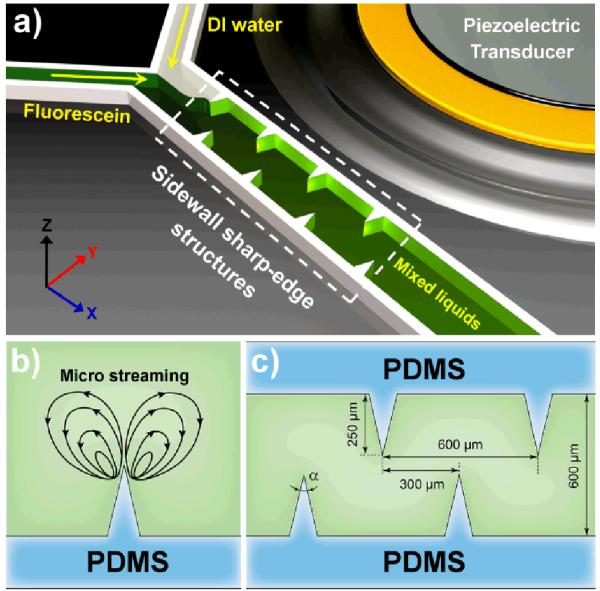
Figure 1a shows the experimental setup of the sharp-edge-based acoustofluidic micromixer. A single-layer polydimethylsiloxane (PDMS) channel with eight sharp-edges on its sidewall (four on each side) was fabricated and bonded onto a glass slide. A piezoelectric transducer (model no. 273-073, RadioShack Corp.) was then attached adjacent to the PDMS channel using an epoxy (PermaPoxy™ 5 Minute General Purpose, Permatex). Upon the actuation of the piezoelectric transducer, the sharp-edges were acoustically oscillated to generate a pair of counter-rotating vortices (double-ring recirculating flows) in the fluid around the tip of each sharp-edge, as shown in Fig. 1b. The double-ring recirculating flows will drastically enhance the mass transport across the channel width by breaking the interface of laminar fluids. Figure 1c shows the design of the microchannel with sidewall sharp-edges. The length, width and depth of the microchannel were 1 cm, 600 μm, and 50 μm, respectively; each sharp-edge was designed to be of a constant height of 250 μm and variable tip angle (α). Four different tip angles (15°, 30°, 45° and 60°) were chosen to investigate the resulting acoustic streaming effect and determine the optimal angle for best mixing performance.
Fig. 1.
(a) Schematic of the sharp-edge-based acoustofluidic mixing device. This device includes a PDMS microfluidic channel and a piezoelectric transducer. (b) Schematic showing the acoustic streaming phenomenon around the tip of an acoustically oscillated sharp-edge. (c) Schematic showing the design of the channel and sharp-edge.
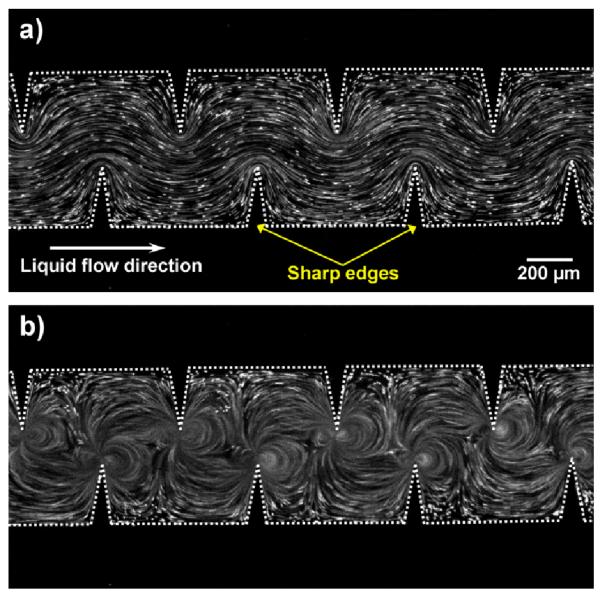
To demonstrate and characterize the fluid flow pattern inside the channel due to the acoustic streaming, a solution containing 1.9 μm diameter dragon green fluorescent beads (Bangs Laboratory) was first infused into the channel. Figure 2a shows the flow pattern of fluorescent beads in the absence of acoustic activation (with the piezoelectric transducer OFF). In the presence of acoustic activation (with the piezoelectric transducer ON), oscillating sharp-edges induced a strong acoustic streaming effect (Fig. 2b). The streaming greatly enhanced the mass transport of the two fluids by perturbing the bulk flow and breaking the interface of laminar flow, thereby enabling fast and homogeneous mixing. A video showing the acoustic streaming phenomenon can be found in the ESI (Video 1).
Fig. 2.
Characterization of the flow pattern with/without acoustic streaming. (a) In the absence of acoustic waves, a laminar flow pattern was observed in a solution containing fluorescent beads. (b) In the presence of acoustic waves, acoustic streaming was developed in the liquid around the tips of sharp-edges.
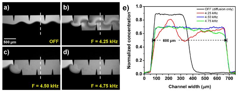
The mixing performance of our sharp-edge-based micromixer was characterized by injecting DI water and fluorescent dye (fluorescein) into the channel through two separate inlets. The sharp-edges were acoustically oscillated by the piezoelectric transducer, which was driven by an amplified sine-wave signal from a function generator and an amplifier. To determine the frequency at which the oscillating sharp-edges generate the strongest acoustic streaming effect, we first tested the device with 15° sharp-edges, and swept the frequency with a 50 Hz increment from 1 kHz to 100 kHz. Our experimental results indicated that the strongest acoustic streaming effect was generated when the sharp-edges were excited at the frequency of 4.50 kHz. Figure 3a shows the unmixed laminar flow profile at a flow rate of 1 μl/min with the piezoelectric transducer OFF, in which a clear fluid interface was observed. Figures 3b—d show the mixing results due to the presence of acoustic waves at frequencies of 4.25 kHz, 4.50 kHz, and 4.75 kHz, respectively. Homogeneous mixing of DI water and fluorescein was achieved when the sharp-edges were excited at frequencies of 4.50 kHz and 4.75 kHz, while incomplete mixing was observed at a frequency of 4.25 kHz. To further verify the mixing performance and identify the optimized driving frequency of the piezoelectric transducer, the cross-sectional dye concentration profiles (the dashed lines in Fig. 3) were plotted by measuring the grey scale value of the experimental images. Figure 3e shows the normalized dye concentration profile across the channel width for the three driving frequencies. The concentration profiles show that a uniform gray-scale value distribution across the channel width was observed at a frequency of 4.50 kHz, suggesting that 4.50 kHz is the proper driving frequency to develop the strongest acoustic streaming phenomenon and achieve optimized mixing performance. As a result, the frequency of 4.50 kHz was used in all the following experiments.
Fig. 3.
Characterization of the mixing performance of the sharp-edge-based acoustofluidic micromixer under different driving frequencies of the piezoelectric transducer. (a) A laminar flow pattern was observed when the piezoelectric transducer was off. (b) 4.25 kHz: Incomplete mixing. (c) 4.50 kHz and (d) 4.75 kHz: Excellent mixing was achieved. (e) Plots of normalized fluorescent concentration across the width of channel.
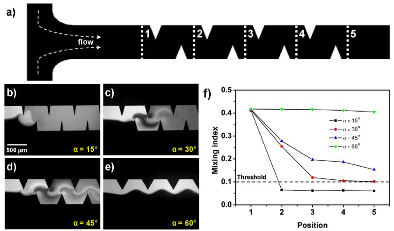
Once the driving frequency was determined, we investigated the effect of the tip angle of sharp-edges on the mixing performance. To quantitatively characterize the mixing performance along the entire length of the channel, we measured the mixing index (M) of fluids at five different positions (indicated as 1, 2, 3, 4, and 5 in Fig. 4a) along the channel. The mixing index is defined as the standard deviation of normalized gray-scale values, which were extracted from the experimental images obtained. A mixing index of 0.5 indicates completely unmixed fluids, while a mixing index of 0.0 indicates completely mixed fluids. A mixing index of 0.1 was chosen as the upper-level threshold for acceptable mixing. Figure 4 shows the mixing efficiencies of the four different tip angles of sharp-edges at a flow rate of 2 μl/min (4 μl/min for the total flow rate of the two co-injected fluids), a driving frequency of 4.50 kHz, and a driving voltage of 31 V (peak to peak). With a tip angle of 15°, a mixing index of 0.065 was achieved at position 2, suggesting excellent mixing of DI water and fluorescein. For sharp-edges with a tip angle of 30°, acceptable mixing was observed only at position 5, suggesting that a longer mixing distance was required. Incomplete mixing was observed for sharp-edges with a tip angle of 45° (Fig. 4d). With a tip angle of 60°, a side-by-side laminar flow was observed due to the unmixed fluids (even in the presence of acoustic wave), and only negligible mixing, which was caused by diffusion, was observed at downstream positions (Fig. 4e). The results showed that as the tip angle of sharp-edges decreased, the mixing performance significantly improved. The results can be explained by approximating the oscillation of sharp-edges as the cantilever vibration. For cantilever vibration, one can use the following equation,
| (1) |
where k is the spring constant, E is the Young’s modulus of material, w is the width of cantilever, t is the thickness of the cantilever, and L is the length of the cantilever. Sharp-edges with different tip angles in this study all have the same values for Young’s modulus, equivalent widths (50 μm), and equivalent lengths (250 μm). The only variable that changes with varying tip angles is the thickness, which increases as the angle increases. Thus sharp-edges with a smaller tip angle should have a lower spring constant. If the input power is constant, a lower spring constant of the cantilever will cause a larger vibration amplitude at the free end of the cantilever. Treating each single sharp-edge as one cantilever, similarly, the sharp-edges with a tip angle of 15° should have the largest vibration amplitude because of its smallest spring constant. This explains why the sharp-edges with the tip angle of 15° induced stronger acoustic streaming effects than those with tip angles of 30°, 45°, or 60°.
Fig. 4.
Characterization of the mixing performance with different tip anlges of sharp-edges. (a) Schematic of the microchannel with sidewall sharp-edges. The mixing index was characterized at five different positions (positions 1–5, indicated by the dashed white lines in the figure). (b) 15°: Excellent mixing was quickly achieved after position 2. (c) 30°: Acceptable mixing was achieved after position 4. (d) 45°: Incomplete mixing. (e) 60°: A laminar flow pattern was observed even if the piezoelectric transducer was ON. (f) Plots of mixing indices at different positions along the microchannel with different tip angles of sharp-edges.
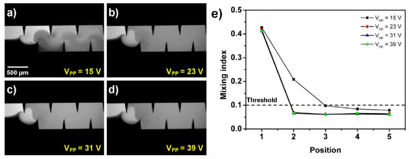
Mixing performance was further characterized by applying different driving voltages to the piezoelectric transducer. Figure 5 shows the mixing performance with different driving voltages at a flow rate of 2 μl/min and a driving frequency of 4.50 kHz. The results show that as the driving voltage of the piezoelectric transducer increased, the mixing efficiency was improved, and acceptable mixing was observed starting from position 2 with driving voltages of 23 VPP, 31 VPP, and 39 VPP. With a driving voltage of 15 VPP, the acceptable mixing index was achieved at position 3, suggesting that a lower driving voltage induced weaker acoustic streaming effects; therefore a longer mixing distance was required.
Fig. 5.
Characterization of the mixing performance under different driving voltages. (a) 15V: Acceptable mixing was achieved after position 3. (b) 23V, (c) 31V, and (d) 39V: Acceptable mixing was quickly achieved after position 2. (e)Plots of mixing indices at different positions along the microchannel under different driving voltages.
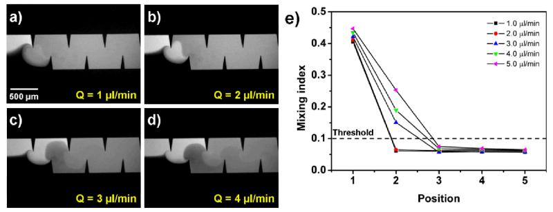
Figure 6 shows the mixing efficiency at different flow rates (1, 2, 3, 4, and 5 μl/min) with a driving frequency of 4.50 kHz and a driving voltage of 31 VPP. At lower flow rates (1 and 2 μl/min), acceptable mixing was achieved at position 2, which suggests excellent mixing of the two fluids and shorter mixing distances were required for low flow rates (Figs. 6a and 6b). For higher flow rates (3, 4, and 5 μl/min), the mixing index at position 2 was increased with an increase in flow rate, and acceptable mixing was only observed after passing position 3. The results suggest that the mixing index increases as flow rate increases, since the ability to oscillate sharp-edges to induce acoustic streaming might be suppressed by high flow rates. The upper limit of flow rate, by which we achieved a mixing index less than 0.1 after passing position 2 (after the first pair of sharpedges), was 2 μl/min (4 μl/min for the total flow rate of two coinjected fluids) . Although mixing indices less than 0.1 were achieved with the flow rates higher than 2 μl/min, they were only observed after passing position 3, suggesting a longer mixing distance.
Fig. 6.
Characterization of the mixing performance under different flow rates. (a) 1 μl/min: Excellent mixing due to low flow rate. (b) 2 μl/min: Acceptable mixing was achieved. (c) 3 μl/min and (d) 4 μl/min: Acceptable mixing was achieved only after position 3. (f) Plots of mixing indices at different positions along the microchannel under different flow rates.
Finally we characterized the mixing time of the sharp-edgebased micromixer. The average mixing time (τs) was estimated using the following equation,
| (2) |
where τ s is the mixing time, Lmix is the distance from unmixed to completely mixed regions, and Vavg is the average fluid velocity. The mixing distance was measured to be approximately 400 μm from Fig. 6b, and the average fluid velocity was calculated to be 2.2 mm/s by dividing the combined flow rate by the cross-sectional area of the channel (600 μm by 50 μm). The mixing time was thus calculated to be around 180 ms which is comparable to those of existing microfluidic mixers.42-45,51,53 We believe that the mixing time can be further shortened through the optimization of design parameters, such as the distance between consecutive single sharp-edge or the height of sharp-edges.
In conclusion, we present an acoustofluidic micromixer based on the acoustic streaming effects induced by oscillating sharp-edges. The recirculating flows induced by the oscillation of sharp-edges allow two fluids to interchange and thus enhances the mass transport across the channel, greatly improving the mixing efficiency. We have demonstrated that homogeneous mixing across the channel width can be achieved and the mixing time was calculated to be ~180 ms. The effects of the sharp-edge geometry, the driving frequency, the driving voltage, and the flow rates on mixing performance were thoroughly investigated. Our sharp-edge-based acoustofluidic micromixer has many desirable characteristics, such as its excellent mixing performance, simplicity, convenient and stable operation, fast mixing speed, and ability to be toggled on-and-off. These characteristics make it promising for a wide variety of lab-on-a-chip applications.
Supplementary Material
Acknowledgements
This research was supported by National Institutes of Health (Director’s New Innovator Award, 1DP2OD007209-01), National Science Foundation, and the Penn State Center for Nanoscale Science (MRSEC) under grant DMR-0820404. Components of this work were conducted at the Penn State node of the NSF-funded National Nanotechnology Infrastructure Network. We thank Christine Truong for helpful discussion.
Footnotes
Electronic Supplementary Information (ESI) available: Video of acoustic streaming induced by acoustically oscillated sharp-edges
references
- 1.Pollack L, Tate MW, Darnton NC, Knight JB, Gruner SM, Eaton W. a, Austin RH. Proceedings of the National Academy of Sciences. 1999;96:10115–10117. doi: 10.1073/pnas.96.18.10115. [DOI] [PMC free article] [PubMed] [Google Scholar]
- 2.Xie Y, Ahmed D, Lapsley MI, Lin S-CS, Nawaz AA, Wang L, Huang TJ. Analytical chemistry. 2012;84:7495–501. doi: 10.1021/ac301590y. [DOI] [PMC free article] [PubMed] [Google Scholar]
- 3.DeMello J, DeMello A. Lab on a Chip. 2004;4:11N. doi: 10.1039/b403638g. [DOI] [PubMed] [Google Scholar]
- 4.Hung L-H, Teh S-Y, Jester J, Lee AP. Lab on a chip. 2010;10:1820–5. doi: 10.1039/c002866e. [DOI] [PubMed] [Google Scholar]
- 5.Capretto L, Cheng W, Carugo D, Katsamenis OL, Hill M, Zhang X. Nanotechnology. 2012;23:375602. doi: 10.1088/0957-4484/23/37/375602. [DOI] [PubMed] [Google Scholar]
- 6.Schabas G, Yusuf H, Moffitt MG, Sinton D. Langmuir : the ACS journal of surfaces and colloids. 2008;24:637–43. doi: 10.1021/la703297q. [DOI] [PubMed] [Google Scholar]
- 7.Yang S, Guo F, Kiraly B, Mao X, Lu M, Huang TJ. Lab on a chip. 2012;12:2097–102. doi: 10.1039/c2lc90046g. [DOI] [PMC free article] [PubMed] [Google Scholar]
- 8.Ho C, Tai Y. Journal of Fluids Engineering. 1996;118:437–47. [Google Scholar]
- 9.Whitesides GM. Nature. 2006;442:368–73. doi: 10.1038/nature05058. [DOI] [PubMed] [Google Scholar]
- 10.Mao X, Waldeisen JR, Juluri BK, Huang TJ. Lab on a chip. 2007;7:1303–8. doi: 10.1039/b708863a. [DOI] [PubMed] [Google Scholar]
- 11.Mao X, Juluri BK, Lapsley MI, Stratton ZS, Huang TJ. Microfluidics and Nanofluidics. 2009;8:139–44. [Google Scholar]
- 12.Nguyen N-T, Wu Z. Journal of Micromechanics and Microengineering. 2005;15:R1–R16. [Google Scholar]
- 13.Capretto L, Cheng W, Hill M, Zhang X. Microfluidics. 2011:27–68. doi: 10.1007/128_2011_150. [DOI] [PubMed] [Google Scholar]
- 14.Neuzil P, Giselbrecht S, Länge K, Huang TJ, Manz A. Nature Reviews Drug Discovery. 2012;11:620–32. doi: 10.1038/nrd3799. [DOI] [PMC free article] [PubMed] [Google Scholar]
- 15.Mao X, Huang TJ. Lab on a Chip. 2012;12:4006–9. doi: 10.1039/c2lc90100e. [DOI] [PMC free article] [PubMed] [Google Scholar]
- 16.Mao X, Huang TJ. Lab on a Chip. 2012;12:1412–6. doi: 10.1039/c2lc90022j. [DOI] [PMC free article] [PubMed] [Google Scholar]
- 17.Guo F, Lapsley MI, Nawaz AA, Zhao Y, Lin S-CS, Chen Y, Yang S, Zhao X-Z, Huang TJ. Analytical chemistry. 2012;84:10745–9. doi: 10.1021/ac302623z. [DOI] [PMC free article] [PubMed] [Google Scholar]
- 18.Song H, Ismagilov RF. Journal of the American Chemical Society. 2003;125:14613–9. doi: 10.1021/ja0354566. [DOI] [PMC free article] [PubMed] [Google Scholar]
- 19.Miller EM, Wheeler AR. Analytical and bioanalytical chemistry. 2009;393:419–26. doi: 10.1007/s00216-008-2397-x. [DOI] [PubMed] [Google Scholar]
- 20.Hsu C-H, Folch A. Applied Physics Letters. 2006;89:144102. [Google Scholar]
- 21.Hossain S, Ansari MA, Kim KY. Chemical Engineering Journal. 2009;150:492–501. [Google Scholar]
- 22.Mao X, Waldeisen JR, Huang TJ. Lab on a chip. 2007;7:1260–2. doi: 10.1039/b711155j. [DOI] [PubMed] [Google Scholar]
- 23.Mao X, Lin S-CS, Dong C, Huang TJ. Lab on a chip. 2009;9:1583–9. doi: 10.1039/b820138b. [DOI] [PubMed] [Google Scholar]
- 24.Wang T-H, Peng Y, Zhang C, Wong PK, Ho C-M. Journal of the American Chemical Society. 2005;127:5354–9. doi: 10.1021/ja042642i. [DOI] [PubMed] [Google Scholar]
- 25.Knight J, Vishwanath A, Brody J, Austin R. Physical Review Letters. 1998;80:3863–66. [Google Scholar]
- 26.Lee C-Y, Lee G-B, Fu L-M, Lee K-H, Yang R-J. Journal of Micromechanics and Microengineering. 2004;14:1390–8. [Google Scholar]
- 27.Harnett CK, Templeton J, Dunphy-Guzman K. a, Senousy YM, Kanouff MP. Lab on a chip. 2008;8:565–72. doi: 10.1039/b717416k. [DOI] [PubMed] [Google Scholar]
- 28.Sigurdson M, Wang D, Meinhart CD. Lab on a chip. 2005;5:1366–73. doi: 10.1039/b508224b. [DOI] [PubMed] [Google Scholar]
- 29.Ng WY, Goh S, Lam YC, Yang C, Rodríguez I. Lab on a chip. 2009;9:802–9. doi: 10.1039/b813639d. [DOI] [PubMed] [Google Scholar]
- 30.Coleman JT, McKechnie J, Sinton D. Lab on a chip. 2006;6:1033–9. doi: 10.1039/b602085b. [DOI] [PubMed] [Google Scholar]
- 31.Yang R-J, Wu C-H, Tseng T-I, Huang S-B, Lee G-B. Japanese Journal of Applied Physics. 2005;44:7634–7642. [Google Scholar]
- 32.Neils C, Tyree Z, Finlayson B, Folch A. Lab on a chip. 2004;4:342–50. doi: 10.1039/b314962e. [DOI] [PubMed] [Google Scholar]
- 33.Lim TW, Son Y, Jeong YJ, Yang D-Y, Kong H-J, Lee K-S, Kim D-P. Lab on a chip. 2011;11:100–3. doi: 10.1039/c005325m. [DOI] [PubMed] [Google Scholar]
- 34.Ryu KS, Shaikh K, Goluch E, Fan Z, Liu C. Lab on a chip. 2004;4:608–13. doi: 10.1039/b403305a. [DOI] [PubMed] [Google Scholar]
- 35.Zhu G-P, Nguyen N-T. Lab on a chip. 2012;12:4772–80. doi: 10.1039/c2lc40818j. [DOI] [PubMed] [Google Scholar]
- 36.Tsai J, Lin L. Sensors and Actuators A: Physical. 2002;97-98:665–671. [Google Scholar]
- 37.Hellman AN, Rau KR, Yoon HH, Bae S, Palmer JF, Phillips KS, Allbritton NL, Venugopalan V. Analytical chemistry. 2007;79:4484–92. doi: 10.1021/ac070081i. [DOI] [PubMed] [Google Scholar]
- 38.Lin S-CS, Mao X, Huang TJ. Lab on a chip. 2012;12:2766–70. doi: 10.1039/c2lc90076a. [DOI] [PMC free article] [PubMed] [Google Scholar]
- 39.Ding X, Lin S-CS, Kiraly B, Yue H, Li S, Shi J, Benkovic SJ, Huang TJ. Proceeding of National Academy of Sciences of the United States of America (PNAS) 2012;109:11105–9. doi: 10.1073/pnas.1209288109. [DOI] [PMC free article] [PubMed] [Google Scholar]
- 40.Shi J, Mao X, Ahmed D, Colletti A, Huang TJ. Lab on a chip. 2008;8:221–3. doi: 10.1039/b716321e. [DOI] [PubMed] [Google Scholar]
- 41.Rezk AR, Qi A, Friend JR, Li WH, Yeo LY. Lab on a chip. 2012;12:773–9. doi: 10.1039/c2lc21065g. [DOI] [PubMed] [Google Scholar]
- 42.Tseng W-K, Lin J-L, Sung W-C, Chen S-H, Lee G-B. Journal of Micromechanics and Microengineering. 2006;16:539–548. [Google Scholar]
- 43.Wixforth A, Strobl C, Gauer C, Toegl A, Scriba J, Guttenberg Z. v. Analytical and bioanalytical chemistry. 2004;379:982–91. doi: 10.1007/s00216-004-2693-z. [DOI] [PubMed] [Google Scholar]
- 44.Frommelt T, Kostur M, Wenzel-Schäfer M, Talkner P, Hänggi P, Wixforth A. Physical Review Letters. 2008;100:034502. doi: 10.1103/PhysRevLett.100.034502. [DOI] [PubMed] [Google Scholar]
- 45.Yaralioglu GG, Wygant IO, Marentis TC, Khuri-Yakub BT. Analytical chemistry. 2004;76:3694–8. doi: 10.1021/ac035220k. [DOI] [PubMed] [Google Scholar]
- 46.Sritharan K, Strobl CJ, Schneider MF, Wixforth A, Guttenberg Z. Applied Physics Letters. 2006;88:054102. [Google Scholar]
- 47.Yu H, Kwon J, Kim E. Journal of Microelectromechanical Systems. 2006;15:1015–1024. [Google Scholar]
- 48.Yang Z, Matsumoto S, Goto H, Matsumoto M, Maeda R. Sensors and Actuators A: Physical. 2001;93:266–272. [Google Scholar]
- 49.Oberti S, Neild A, Ng TW. Lab on a chip. 2009;9:1435–8. doi: 10.1039/b819739c. [DOI] [PubMed] [Google Scholar]
- 50.Marmottant P, Hilgenfeldt S. Nature. 2003;423:153–156. doi: 10.1038/nature01613. [DOI] [PubMed] [Google Scholar]
- 51.Liu RH, Yang J, Pindera MZ, Athavale M, Grodzinski P. Lab on a chip. 2002;2:151–7. doi: 10.1039/b201952c. [DOI] [PubMed] [Google Scholar]
- 52.Tovar AR, Lee AP. Lab on a chip. 2009;9:41–3. doi: 10.1039/b812435c. [DOI] [PubMed] [Google Scholar]
- 53.Ahmed D, Mao X, Shi J, Juluri BK, Huang TJ. Lab on a chip. 2009;9:2738–41. doi: 10.1039/b903687c. [DOI] [PubMed] [Google Scholar]
- 54.Ahmed D, Mao X, Juluri BK, Huang TJ. Microfluidics and Nanofluidics. 2009;7:727–731. [Google Scholar]
- 55.Rodaree K, Maturos T, Chaotheing S, Pogfay T, Suwanakitti N, Wongsombat C, Jaruwongrungsee K, Wisitsoraat A, Kamchonwongpaisan S, Lomas T, Tuantranont A. Lab on a chip. 2011;11:1059–64. doi: 10.1039/c0lc00419g. [DOI] [PubMed] [Google Scholar]
- 56.Ahmed D, Chan CY, Lin S-CS, Muddana HS, Nama N, Benkovic SJ, Huang TJ. Lab on a chip. 2013;13:328–31. doi: 10.1039/c2lc40923b. [DOI] [PMC free article] [PubMed] [Google Scholar]
- 57.Huang P-H, Lapsley MI, Ahmed D, Chen Y, Wang L, Jun Huang T. Applied physics letters. 2012;101:141101. doi: 10.1063/1.4742864. [DOI] [PMC free article] [PubMed] [Google Scholar]
- 58.Hashmi A, Heiman G, Yu G, Lewis M, Kwon H-J, Xu J. Microfluidics and Nanofluidics. 2012;14:591–596. [Google Scholar]
- 59.Hashmi A, Yu G, Reilly-Collette M, Heiman G, Xu J. Lab on a chip. 2012;12:4216–27. doi: 10.1039/c2lc40424a. [DOI] [PubMed] [Google Scholar]
- 60.Xu Y, Hashmi A, Yu G, Lu X, Kwon H-J, Chen X, Xu J. Applied Physics Letters. 2013;102:023702. [Google Scholar]
- 61.Patel MV, Tovar AR, Lee AP. Lab on a chip. 2012;12:139–45. doi: 10.1039/c1lc20626e. [DOI] [PubMed] [Google Scholar]
- 62.Bruus H, Dual J, Hawkes J, Hill M, Laurell T, Nilsson J, Radel S, Sadhal S, M Wiklund. Lab on a chip. 2011;11:3579–80. doi: 10.1039/c1lc90058g. [DOI] [PubMed] [Google Scholar]
- 63.Shi J, Ahmed D, Mao X, Lin S-CS, Lawit A, Huang TJ. Lab on a chip. 2009;9:2890–5. doi: 10.1039/b910595f. [DOI] [PubMed] [Google Scholar]
- 64.Shi J, Huang H, Stratton Z, Huang Y, Huang TJ. Lab on a chip. 2009;9:3354–9. doi: 10.1039/b915113c. [DOI] [PubMed] [Google Scholar]
Associated Data
This section collects any data citations, data availability statements, or supplementary materials included in this article.


