Abstract
Three-dimensional (3D) brain organoids derived from human pluripotent stem cells (hPSCs), including human embryonic stem cells (hESCs) and induced pluripotent stem cells (iPSCs), have become a powerful system to study early development events and to model human disease. Cerebral organoids are generally produced in static culture or in a culture vessel with active mixing, and the two most widely used systems for mixing are a large spinning flask and a miniaturized multi-well spinning bioreactor (also known as Spin Omega (SpinΩ)). The SpinΩ provides a system that is amenable to drug testing, has increased throughput and reproducibility, and utilizes less culture media. However, technical limitations of this system include poor stability of select components and an elevated risk of contamination due to the inability to sterilize the device preassembled. Here, we report a new design of the miniaturized bioreactor system, which we term Spinfinity (Spin∞) that overcomes these concerns to permit long-term experiments. This updated device is amenable to months-long (over 200 days) experiments without concern of unexpected malfunctions.
Keywords: Pluripotent stem cells, Brain organoid, Bioreactor, 3D printing, Long term culture, Cortical differentiation
1. Hardware in context
Brain organoids are three-dimensional (3D) structures formed from neural stem cells (NSCs) derived from human pluripotent stem cells (hPSCs) that can effectively model human brain development up to 12–14 weeks post-conception [1–4], a time period which includes critical patterning events in the cerebral cortex and other brain regions [5,6]. On a cellular level, brain organoids show a high level of similarity to the in vivo developing human brain in the early stages of development, including progenitor zones (ventricular zone and subventricular zone consisting of Paired box protein-6 (PAX6) +/ Sex determining region Y-box2 (SOX2) + NSCs) that form around central lumens [1,4]. These 3D organoid cultures therefore provide a robust system amenable to extended cultivation and manipulation, which makes them a useful tool to model development and disease in the context of the complex brain microenvironment [7–9].
Specifications table
| Hardware name | Spin∞ |
|---|---|
| Subject area | Neuroscience |
| Hardware type | Biological sample handling and preparation |
| Open Source License | CC-BY-SA 4.0 |
| Cost of Hardware | $2500 |
| Source File Repository | https://doi.org/10.17605/OSF.IO/FV9T4 |
Recently, two protocols have been published on enhancing cortical plate formation within hPSC-derived cerebral organoids: one using large spinner flasks and microfilaments as a solid support [1,10] and another that uses a miniature spinning bioreactor termed Spin Omega (SpinΩ) [11,12], which consists of 3D printed gears and paddles driven by a single electric motor. The SpinΩ provide an accessible and versatile format for culturing brain-region-specific organoids due to its reduced incubator footprint, decreased media consumption (3 mL of media per well compared to 75–100 mL of media per spinner [8]), and increased throughput, but several technical caveats limit its use in long-term experiments, most prominently the choice of components used to fabricate the device and the design of the device with respect to limiting the chances of contamination and mechanical failure. Here, we redesigned the SpinΩ to overcome these problems, leading to the creation of a device that we have termed Spinfinity (Spin∞).
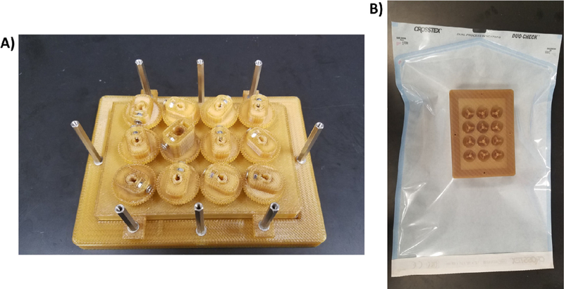
To develop this improved device, we first considered the choice of motor that drives the spinning bioreactor. Motor life span inside an incubator can be a major hurdle when using a bioreactor system because motors that are not designed to withstand harsh environments (high humidity, 5% carbon dioxide, and elevated heat) can easily corrode and break, leading to unexpected failures in the middle of long-term experiments. We therefore selected a DC 12V 100RPM gear motor with the ability to operate at increased temperatures (max 70 °C) and humidity (90% humidity). Additionally, parylene C vapor deposition was applied to the motor to provide an additional moisture barrier to further the lifetime of the motor and increase durability [13]. Next, we considered the basic design of the bioreactor. Due to the humidity issue raised above, we used stainless steel screws, standoffs, nuts, and washers in order to reduce the oxidation of the metal and prolong the life of the bioreactor. These parts also have the advantage of being autoclavable as separate components or with the assembled bioreactor, and the updated design now allows the majority of the equipment (including the 3D printed parts) to be assembled and autoclaved to reduce external handling and improve sterility. The addition of an upper acrylic lid on the bioreactor (where the motor is anchored) further enhances stability and consistency of the device. The SpinΩ motor was anchored in two points on the upper lid, which frequently caused the motor to shift and oscillate, thereby putting unnecessary additional stress on the motor leading to eventual failure. Because the updated Spin∞ was designed using a separate acrylic sheet, hex standoffs, and a larger, more durable motor, all components are kept in1perpendicular alignment to the well plate, thus preventing shifting and oscillation. Additionally, because the Spin∞ is designed with hex standoffs and an autoclavable 3D printed base, the lid is securely placed on the 12-well plate, which prevents spills and possible contamination points. By comparison, the original SpinΩ design freely rests on the top of the plate, making this design prone to spillage and contamination. Overall, these changes yield a miniaturized spinning bioreactor that is exceptionally easy to maintain and performs consistently. This updated device is amenable to months-long experiments without concern of unexpected malfunctions. Compared with the previous versions of the bioreactor, our system minimizes the manipulation post-sterilization since all parts, excluding the acrylic and motor, is able to be autoclaved while assembled. The increased stability provided by the acrylic lid and the base reduces the chances of contamination as it maintains the bioreactor lid firmly in place during transit from and to the incubator.
2. Hardware description
The Spin∞ is built primarily from 3D printed ULTEM 1010 resin to permit autoclaving. Alternate 3D printing filaments, such as acrylonitrile butadiene styrene (ABS), can be used but require more extensive sterilization steps such as sequential washes in 10% bleach, 70% ethanol, distilled water washes and UV irradiation. The bottom 3D printed frame contains an inset to hold a 12-well plate, as well as inserts for the metal standoffs. The top 3D printed frame houses polytetrafluoroethylene (PTFE) collars, gears, and paddles, which are manually assembled. All of the gears except one are used solely for turning, while the remaining gear connects directly to a DC 12V 100RPM gear motor (Greartisan) attached to an acrylic plate. The acrylic plate rests on the metal standoffs and is screwed into place to ensure mechanical stability. All components can be optionally coated with parylene C to prevent corrosion of the metal housing on the motor and to add an additional hydrophobic barrier to prevent absorption of media into the 3D printed parts. The motor connects to a L298n bridge and a Raspberry Pi 3A+ that controls the motor speed through a touchscreen interface.
Increased motor life span under high temperature and humidity conditions.
Can be autoclaved after assembly, thus removing the need for disassembly for cleaning and sterilization.
Sturdy, fully enclosed assembly to prevent leaks and spills while ensuring consistent operation.
Integrated touch screen for changing motor speed.
3. Design files
Table 1 contains links to all STL design files for 3D printed parts, the python script for running the bioreactor, and a video demonstration of step-by-step assembly of the device.
Table 1.
Design files.
| Design file name | File type | Open source license | Location of the file |
|---|---|---|---|
| Base | STL | CC-BY-SA 4.0 | https://doi.org/10.17605/OSF.IO/FV9T4 |
| 12-Well Plate Lid | STL | CC-BY-SA 4.0 | https://doi.org/10.17605/OSF.IO/FV9T4 |
| CCW Paddle | STL | CC-BY-SA 4.0 | https://doi.org/10.17605/OSF.IO/FV9T4 |
| CW Paddle | STL | CC-BY-SA 4.0 | https://doi.org/10.17605/OSF.IO/FV9T4 |
| Gear | STL | CC-BY-SA 4.0 | https://doi.org/10.17605/OSF.IO/FV9T4 |
| Motor Shaft Gear | STL | CC-BY-SA 4.0 | https://doi.org/10.17605/OSF.IO/FV9T4 |
| Parylene Template for Gears (Optional) | STL | CC-BY-SA 4.0 | https://doi.org/10.17605/OSF.IO/FV9T4 |
| Parylene Template for Paddles (Optional) | STL | CC-BY-SA 4.0 | https://doi.org/10.17605/OSF.IO/FV9T4 |
| X4 L298n Bridge Holder (Optional) | STL | CC-BY-SA 4.0 | https://doi.org/10.17605/OSF.IO/FV9T4 |
| 5Motors | PY | CC-BY-SA 4.0 | https://doi.org/10.17605/OSF.IO/FV9T4 |
| Spinfinity Assembly | AVI | CC-BY-SA 4.0 | https://doi.org/10.17605/OSF.IO/FV9T4 |
The Base holds a 12-well cell culture plate where the organoids are cultured.
The 12-Well Plate Lid holds the PTFE collars, counter-clockwise (CCW) Paddles, clockwise (CW) Paddles, Gears, and Motor Shaft Gear. This component replaces the traditional lid on a cell culture plate.
The CCW Paddle is partially submerged in the media and carries out mixing in a counter clockwise direction.
The CW Paddle is partially submerged in the media and carries out mixing in a clockwise direction.
The Gear holds the paddles and spins under the control of the motor.
The Motor Shaft Gear directly attaches to the motor and turns all of the other gears.
The Parylene Template for Gears holds the gears during parylene C deposition. This print is optional if the user will not coat with parylene C.
The Parylene Template for Paddles holds the paddles during parylene C deposition. This print is optional if the user will not coat with parylene C.
The X4 L298n Bridge Holder holds four individual bridges for driving the motors.
The 5Motors is a python script to enable touchscreen control over motor speed and direction.
The Spinfinity Assembly is a video showing each step of the bioreactor installation.
All files can be found under the reserved Spinfinity repository: doi: https://doi.org/10.17632/89g9nsd4gk.1
4. Bill of materials
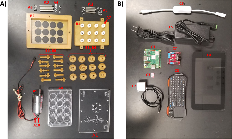
Tables 2–4 contain descriptions, suppliers, and pricing on hardware, 3D prints, and software components. Fig. 1 shows all components. If applicable, the part name in Tables 2–4 contains its corresponding designation in Fig. 1.
Table 2.
Hardware components.
| Quantity | Part Name | Supplier | Part Number | Cost |
|---|---|---|---|---|
| 1 | Acrylic Sheet | McMaster-Carr | 8560K354 | $17.34 |
| 12″ × 12″ × ¼” (part A1) | ||||
| 4/Bioreactor | 18–8 Stainless Steel | McMaster-Carr | 93655A226 | $4.25 |
| 45 mm Hex (part A2) | ||||
| 4/Bioreactor | 18–8 Stainless Steel | McMaster-Carr | 93655A224 | $4.11 |
| 35 mm Hex (part A3) | ||||
| 8/Bioreactor | 18–8 Stainless Steel | McMaster-Carr | 93475A210 | $1.62 (Pack of 100) |
| Washer M3 (part A4) | ||||
| 8/Bioreactor | 18–8 Stainless Steel | McMaster-Carr | 91828A211 | $5.55 (Pack of 100) |
| Hex Nut M3 | ||||
| 0.5 mm Thread (part A5) | ||||
| 14/Bioreactor | 18–8 Stainless Steel | McMaster-Carr | 92010A120 | $4.65 (Pack of 100) |
| Philips Flat Head Screw M3 (part A6) | ||||
| 12/Bioreactor | PTFE Collars (part A7) | McMaster-Carr | 2685t11 | $6.16 |
| 1/Bioreactor | 12-Well Cell Culture Plate (part A8) | Corning | 3737 | $431.00 (Case of 100) |
| 1/Bioreactor | Autoclavable Bags | Fisher Scientific | 01-812-58 | $182.00 (Pack of 100) |
| 1/Bioreactor | Motor 100RPM, 12V, Eccentric Shaft (part A9) | Amazon | B0721T1PXQ | $15.49 |
| 1 Set | Screwdriver Set | McMaster-Carr | 52985A22 | $30.62 |
| 1 Set | Solder | McMaster-Carr | 7667A51 | $38.77 |
| 1 Set | Heat Shrink Tubing | McMaster-Carr | 6334K414 | $12.71 |
Table 4.
Electronic components.
| Quantity | Part Name | Supplier | Part Number | Unit Cost |
|---|---|---|---|---|
| 1/Bioreactor | Raspberry Pi 3 A+ (part C1) | Sparkfun | DEV-15139 | $29.95 |
| 1/Bioreactor | Raspberry Pi 3 A+ Power supply (part C2) | Sparkfun | TOL-13831 | $7.95 |
| 1/Raspberry Pi | Raspberry Pi™ – 16 GB MicroSD NOOBS Card (part C3) | Sparkfun | COM-13945 | $24.95 |
| 1/Raspberry Pi | Raspberry Pi LCD - 7″ Touchscreen (part C4) | Sparkfun | LCD-13733 | $64.95 |
| 1/Bioreactor | Power Supply 12 V, 5A (part C5) | Amazon | B06Y64QLBM | $8.99 |
| 1/8 Bioreactors | 4-way DC Jack Splitter (part C6) | Amazon | B00MHUGL7W | $8.29 |
| 1/Bioreactor | 5 PCS L298N Motor Drive Controller Board | Amazon | B06X9D1PR9 | $15.99 (Pack of 5) |
| 1/Bioreactor | 100ft 4 Pin RGB Extension Cable Wire | Amazon | B074H7DM4B | $16.99 |
| 1/Motor | 2-pin JST SM Male & Female Plug Housing | Amazon | B0188DMF3A | $14.99 |
| 1/L298N Bridge | In-line Power Toggle (Optional) (part C7) | Amazon | B0782JXQNP | $5.85 |
| I/LCD Screen | SmartPi Touch Case (Optional) | Amazon | B01HV97F64 | $27.99 |
| 1/LCD Screen | Wireless Bluetooth Keyboard (part C8) | Amazon | B00BX0YKX4 | $24.99 |
Fig. 1.
All individual components used to build the Spin∞. Photo of all parts needed to build one bioreactor. Please refer to Table 1 for parts list and corresponding labels. A) Hardware and 3D printed components. B) Electronic components.
ULTEM 1010 can be autoclaved and is recommended for 3D prints that will be used under sterile conditions. ABS can be used instead, but several additional steps are required to sterilize the 3D printed parts (parylene C coating and a series of 10% bleach, 70% ethanol, distilled water washes, as well as UV radiation).
The 3D prints for Parylene Template for Plate Gears, Parylene Template for Plate Paddles, and L298n Bridge Holder can be made from ABS because they are not used under sterile conditions.
The Parylene Template for Plate Gears and Parylene Template for Plate Paddles do not need to be printed if the user does not intend to coat with parylene C.
Cost of 3D printed parts depends on quantity ordered and vendor.
5. Build instructions
The essential bioreactor components are 3D printed. The remaining hardware and electronics can be purchased from common suppliers.
The additional tools required for assembly include:
Drill
5 mm drill bit
Philips screwdriver
CO2 laser cutter
Optional: parylene C vapor deposition machine such as a Labcoter supplied by Specialty Coating Systems
Solder and soldering iron
Heat shrink tubing and heat shrink gun
Crimper
JST connectors (male and female)
2-wire (18–20 AWG, 66ft)
5.1. Hardware assembly and operation
5.1.1. Motor preparation
Solder positive and negative terminals (3 ft of 2 wire cable).
Heat shrink tubing to each terminal.
Crimp on male version of the JST plugs.
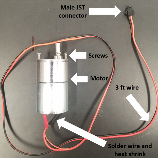
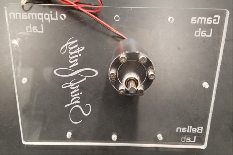
Add 6 screws loosely to motor (Fig. 2).
Optional: coat the entire motor unit with parylene C.
Fig. 2.
Motor preparation. Photo of assembled motor for connecting to the acrylic plate.
5.1.2. Acrylic plate preparation
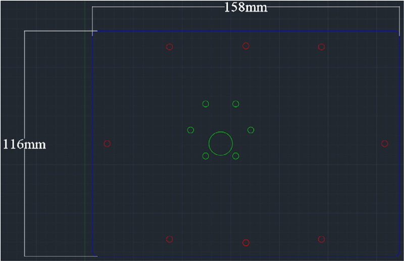
Laser cut the acrylic plate with appropriate dimensions (Fig. 3). Settings will vary based on laser wattage. Here, a 45 W laser cutter was used with 80% power and 70% speed with two passes.
Fig. 3.
Acrylic plate dimensions for laser cutting.
5.1.3. Bioreactor assembly
Optional: coat the 3D printed 12-Well Plate Lid and Base with parylene C.
Optional: attach the paddles and the gears to the 3D printed holders (Parylene Template for Gears and Parylene Template for Paddles) and coat with parylene C. Be sure to place the bottom of the gears facing up to maximize vapor deposition.
Insert the stainless steel M3 nuts in the gears.
Use a 5 mm (diameter of PTFE collar) drill bit to gently core out the center of the PTFE collar and insert into the 12-Well Plate Lid. Be sure to lightly drill out the center of the PTFE collar and remove as little as possible.
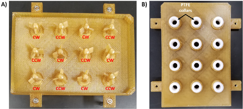
Insert CW Paddles and CCW Paddles into the lid and PTFE collars (Fig. 4). Proper position of each paddle is noted.
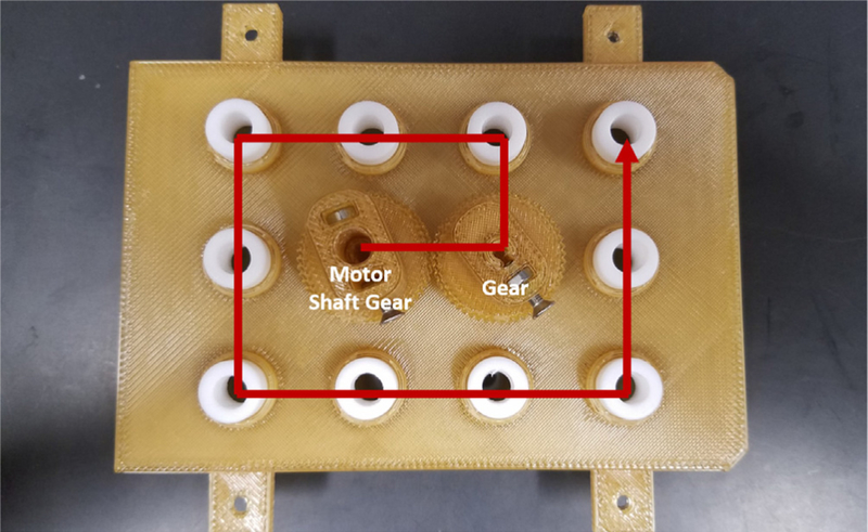
- To attach the Gears, start with the Motor Shaft Gear at the B2 position (Fig. 5).
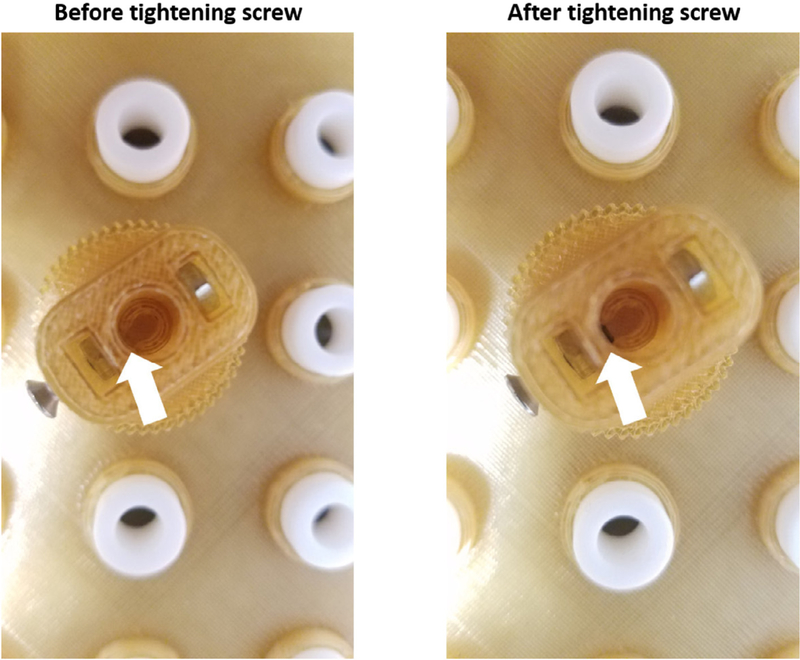
- The bottom set screw gear needs to be aligned with the opening on the paddle.
- Screw in the top screw. Do not screw the screws in any further than what is shown in the image. The shaft should easily and freely spin (Fig. 6).
Attach the other gears to the rest of the wells working counterclockwise around the lid (Fig. 5). The teeth of the gears should be aligned and interlock.
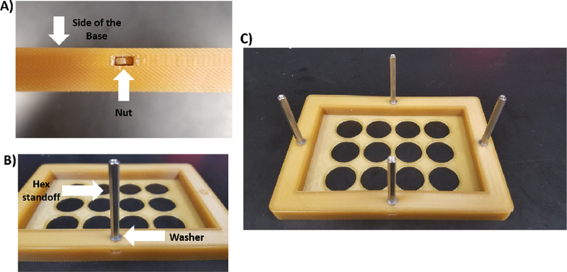
- Attach the hex standoffs and 4 hex nuts to the base (Fig. 7).
- Screw on the 45 mm hex standoffs with washers attached to the 4 locations with the hex nuts on the base.
- Attach screws to hex standoffs.
Attach the hex standoffs to the lid and insert the nuts into the 12-Well Plate Lid (Fig. 8). Screw the 35 mm hex standoffs with washers attached to all the locations with the hex nuts on the lid and attach screws to the hex standoffs.
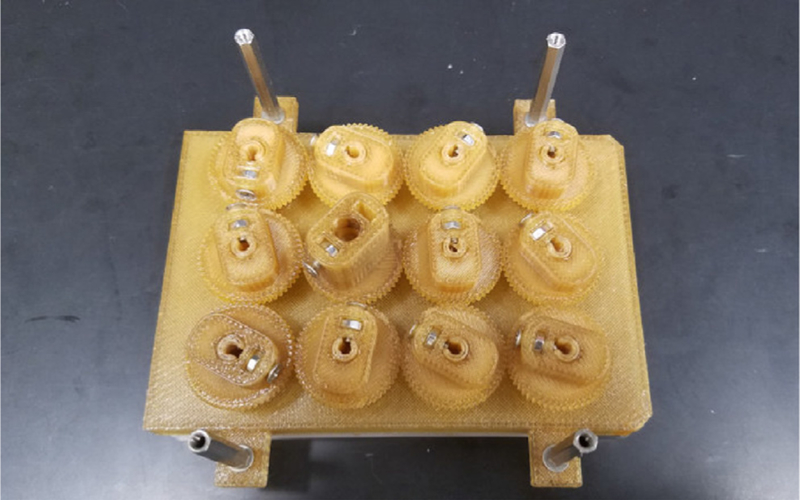
- Autoclave the 3D printed and stainless-steel parts either assembled or as individual pieces for 60 min (Fig. 9).
- Place all autoclavable items in an autoclavable bag upside down, and seal the bag.
- Everything but the motor, acrylic plate, and cell culture plate can be autoclaved.
After autoclaving is complete, spray the autoclave bag with 70% ethanol and transfer it into the biosafety hood. Take the device out of the bag.
Outside of the hood, insert the shaft of the motor through the hole in the acrylic plate, and attach the motor to the acrylic plate using the six 10 mm screws (Fig. 10).
Transfer the motor and acrylic plate into the biosafety hood. The motor and acrylic plate should be sprayed with 70% ethanol for sterilization.
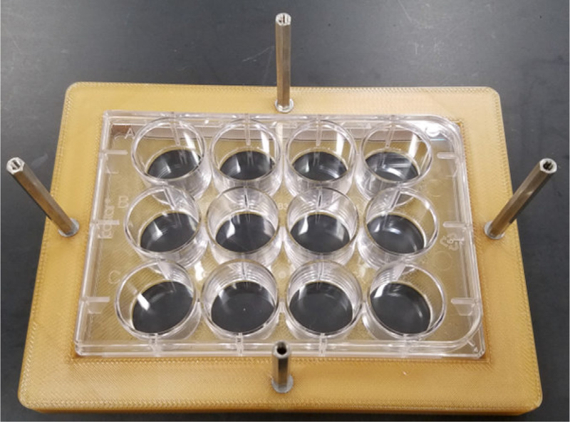
Remove the lid from a sterile 12-well plate and place it into the Base. Add the 12-Well Plate Lid to the top of the plate (Fig. 11).
Take the screws off the hex standoffs. The screws can be stored in a sterile petri dish.
Make sure that the top screw on the Motor Gear Shaft is loosened.
Place the acrylic sheet on top of the hex standoffs. Make sure that the motor shaft goes inside the Motor Shaft Gear.
- Attach the motor to the Motor Gear Shaft (Fig. 12).
- Find the beveled side of the motor shaft and line it up with the top screw of the Motor Shaft Gear.
- By hand, screw the top screw to where there is a little play with the set screw in the shaft.
- Critical: avoid overtightening the top screw of the Motor Gear Shaft.
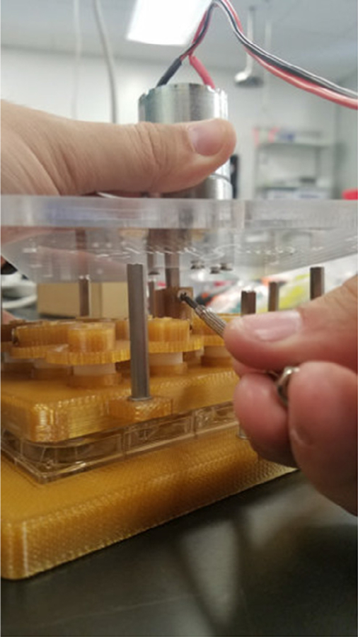
Thread the screws into the 35 mm hex standoffs (12-Well Plate Lid) through the acrylic plate (Fig. 13). Do not tighten completely! There should be some play.
Thread the screws through the acrylic plate to the 45 mm hex standoffs on the Base, and tighten all four screws. These should be securely tightened.
Tighten the screws attached to the 35 mm hex standoffs. Once fully tightened, turn the screws ½ counter clockwise. The screws to the 12-Well Plate Lid hex standoffs are designed to be loose.
Before using with cells, allow the assembled bioreactor to run for at least 24–48 h dry in a 37 °C incubator to remove any debris from the 3D printed parts. Sterile PBS can then be used in the 12-well plates to wash the paddles bioreactor of any remaining debris.
Fig. 4.
Insertion of paddles into the 12-Well Plate Lid. A) Positioning of the CW Paddles and CCW Paddles are noted. B) Positioning of the PTFE collars are shown on the opposite side of the lid.
Fig. 5.
Assembly pattern of the Gears to ensure proper operation. Make sure each gear is properly threaded before moving on to the next one. The position of the Motor Shaft Gear is noted.
Fig. 6.
Proper positioning of screws in the Gears. Screws should be turned to where the threading is just exposed and touching the paddle. Screws should not be overtightened.
Fig. 7.
Attachment of the 45 mm hex standoffs to the Base. A) Each nut is placed into the side of the Base. B) A washer is added to the 45 mm hex standoff, which is then screwed into the nut. C) Image showing all hex standoffs attached to the Base.
Fig. 8.
Attachment of the 35 mm hex standoffs to the 12-Well Plate Lid. The procedure for attaching these standoffs is identical to Fig. 7.
Fig. 9.
Preparation of the bioreactor for autoclaving. A) The Base with the hex standoffs, the 12-Well Plate Lid with the Paddles and Gears, and the stainless-steel screws can all be autoclaved. B) The piece should be placed upside down in an autoclavable bag (the Base should face the clear side of the bag).
Fig. 10.
Attachment of the motor to the acrylic plate.
Fig. 11.
Placement of a 12-well plate into the Base.
Fig. 12.
Attachment of the beveled side of the motor shaft into the Motor Shaft Gear.
Fig. 13.
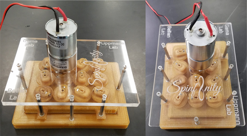
Fully assembled bioreactor. A front and side view of the fully assembled Spinfinity.
5.2. Electronics assembly
5.2.1. Initial assembly
Follow the Raspberry Pi Touchscreen assembly instructions with the Raspberry Pi 3 A + and Raspberry Pi SD card preloaded with Noobs. The Raspberry Pi should be powered by the 5 V microUSB power source provided in the kit.
Once the touchscreen has been assembled, the electronics need to be assembled as described below.
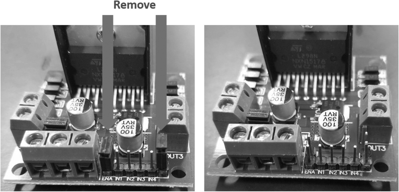
First, remove the jumper from enable A and B on the L298n bridge (Fig. 14).
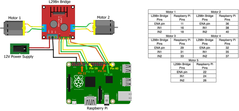
Connect the bridge to the GPIO pins on the Raspberry Pi (Fig. 15). For the first motor, connect the ENA pin on the L298n bridge to GPIO pin 11, connect IN1 on the L298n bridge to GPIO pin 16 and connect the IN2 on the L298n bridge to GPIO pin 18 (Fig. 15). Repeat this for all motors and L298n bridges. Each L298n bridge can control two motors, and using the instructions in Fig. 15, a single Raspberry Pi can run up to five motors.
Connect the in-line power toggle to turn the bridge on and off.
Make sure the L298n bridge has a 12 V input. The ground wire goes to the bridge and the Raspberry Pi. This is essential and will not work without both grounds.
Last, connect 3 feet of 2-wire to the output screw terminals for motor 1 and attach a female JST connector on the other end.
Fig. 14.
Removal of the jumpers from the L298n bridge.
Fig. 15.
Example for how to connect an L298n bridge to two motors and a Raspberry Pi. The accompanying table provides pin locations for connecting the Raspberry Pi to up to five motors.
5.2.2. Software download and installation
Turn on the Raspberry Pi and open the command terminal.
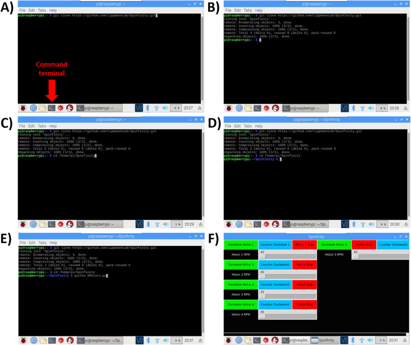
Type the following text in the command line (Fig. 16A–B): git clone https://github.com/LippmannLab/Spinfinity.git
Enter (Fig. 16C): cd/home/pi/Spinfinity
A new line should read (Fig. 16D): pi@raspberrypi: ~/Spinfinity $
Enter (Fig. 16E): python 5Motors.py
The program will now open (Fig. 16F). If the Raspberry Pi is restarted, then open the command terminal again and reenter steps 3–5 to open the program.
Fig. 16.
Software installation setup. A-B) The Command Terminal is opened, and by entering the text shown in the figure, the repository will be cloned from Github into a folder on the Raspberry Pi. C-D) Opening of the repository. E-F) Opening of the software, which leads to the user interface with touchscreen control.
5.3. Media changes
Turn off the motor using the in-line power switch and disconnect the JST connector.
Take the Spin∞ out of the incubator and place it in a biosafety hood.
Unscrew the screws attached to the 45 mm hex standoffs. Do not lose the other screws.
Transfer the 12-Well Plate Lid (that is still attached to the acrylic plate and motor) to a sterile, empty 12 well plate. This will expose the plate of organoids resting in the Base, which can be removed for imaging if desired.
- Change the media:
- Tilt the plate approximately 45°so that the organoids will sink to the bottom of the well.
- Carefully remove the media from each well using a P1000 micropipette and put the spent media into an empty 15 mL conical tube.
- Check the spent media to make sure that no organoids were accidentally removed.
- Once spent media is removed, add 3–4 mL of fresh media to each well using a P1000 micropipette.
Return the 12-Well Plate Lid on top of the 12-well plate that is resting in the Base.
Screw the screws back onto the 45 mm hex standoffs tightly.
Put the device back into the incubator.
Connect the JST connector and turn on the motor. Check to make sure that the gears and paddles are turning at the desired speed.
6. Validation and Characterization
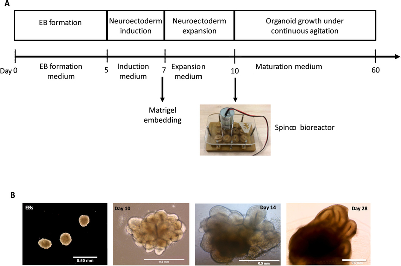
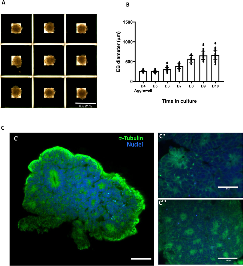
Brain organoids were generated using the STEMdiff™ Cerebral Organoid Kit (Stem Cell Technologies) with some modifications (Fig. 17A and 17B) [1,8,11,14]. As the generation of homogeneous embryoid bodies (EBs) is critical for achieving homogenous organoids, we utilize a 24-well plate AggreWell™ 800 (Stem Cell Technologies, catalog 34815) [15,16] to increase the reproducibility and the yield of EBs (Fig. 18A and 18B). After 4 days of culture in the AggreWells, we transfer the organoids to a 10 cm ultra-low attachment plate to allow further growth of the EBs before the Matrigel embedding process (Fig. 17B). The diameter of the EBs increased over time; by the embedding day (day 7) the average diameter was 387 μm (±57 μm) and by the bioreactor transfer day (day 10) the average diameter was 661 μm (±112 μm) (Fig. 18B) (11–142 technical replicates for each time point in three biological replicates (n = 3)). High resolution images show the formation of organized neural rosettes within the EBs at day 8 [1,11]. Alpha-tubulin (α-tubulin filaments) can be seen organized radially from the lumen (Fig. 18C) [17–20]. These polarized neuroepithelium-like structures resemble neural tube formation and are the precursors to the formation of the brain lobules [10].
Fig. 17.
Protocol for the generation of brain organoids using Spin∞. A) Schematic of the major stages in the culture protocol with key time points. B) Macroscopic images (taken with inverted microscope) of brain organoids at different developmental stages. Scale bars: 0.5 mm.
Fig. 18.
Embryoid body generation and size over time. A) Four day-old embryoid bodies (EB) generated using microwells from Aggrewell. B) Relative growth of the embryoid bodies over time. C) Light sheet microscope images of day 7 embryoid body showing the formation of organized neural rosettes. C” and C” show close up to the neural rosettes. Data are mean ± s.d. Scale bars: (A) 0.5 mm, (C’) 100 lm, (C”) 50 lm, (C”’) 100 μm.
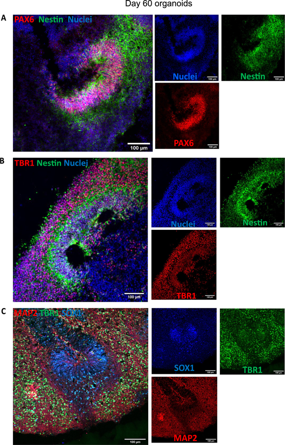
Characterization of the organoids was performed at day 60 (4 technical replicates in each of the three biological replicates (n = 3)) and day 150 (4 technical replicates in one biological replicate (n = 1)). Organoids were fixed in 4% paraformaldehyde (PFA) for 15 min at 4 °C, followed three 5 min washes in phosphate-buffered saline (PBS) and 30% sucrose dehydration overnight at 4 °C. Embedding for sectioning was performed as reported previously [1]. Cryosections (15 lm thick) were stained using neural progenitor cell (NPC), mature pan-neuronal, and cortical layer markers. As previously reported for day 60 organoids [11], the cells that stain positive for neural progenitor markers are localized in the periphery to the ventricle-like structures (Fig. 19A). Multi-layer stratified structures can be readily seen and are comprised of NPC+ cells marked by SOX 1, SOX2, and PAX6 marking the progenitor zone (Fig. 19A–C). PAX6 expression confirmed the forebrain identity in the regions of interest [1]. Nestin positive cells mark radial glia, key structures for the expansion of the mammalian cortex by differentiating into neurons and intermediate progenitor cells (Fig. 19A and B) [21].
Fig. 19.
Staining for neural progenitor cells and cortical neurons. A) Day 60 organoids showing the presence of neural progenitor markers Pax6 and Nestin. B) Cortical plate marker TBR1 shows the organization of the pre-plate. C) MAP2 positive cells indicate the presence of committed neurons at this stage. Immunostainings were repeated on four brain organoids from three independent experiments. Scale bars: (A-C) 100 μm.
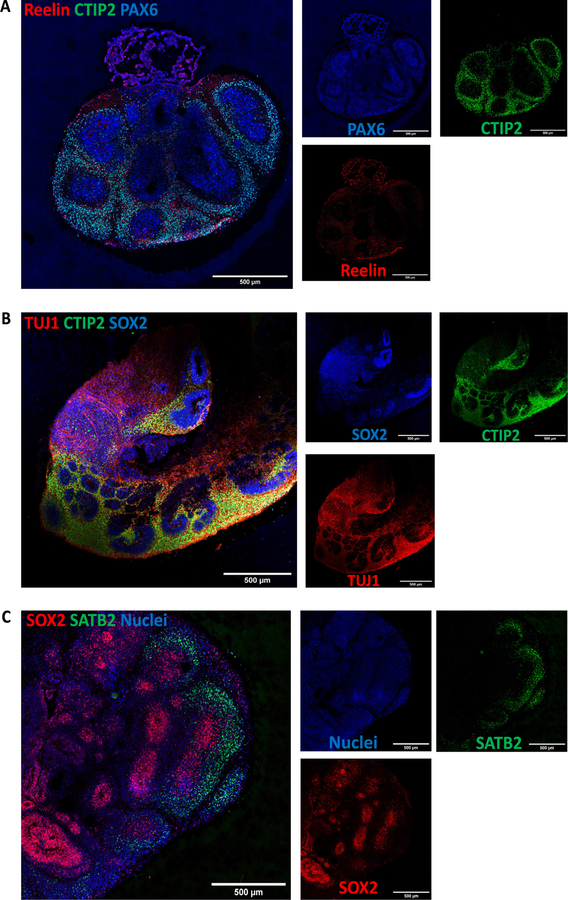
Pre-plate formation was confirmed by the presence of T-box brain (TBR) 1 + cells (Fig. 19B and C). This marker also identifies cells localized to the early-born layer VI of the cortex [22]. TBR1+ neurons are vital for guiding the subsequent neuronal migrations [22]. Radial organization can be seen by Microtubule-associated protein (MAP) 2, a neuronal marker for dendritic outgrowth and branching (Fig. 19C) [23]. Cajal-Retzius cells, a cell population crucial to the generation of the cortical plate architecture, is present by Reelin+ neurons located along the organoid surface (Fig. 20A). These early born cells localize to the marginal zone of the cortex (layer I) and contribute to the formation of the inside-out layering of the neurons in the neocortex [24].
Fig. 20.
Characterization of cortical layers present after 60 days in culture. A) Cajal-Retzius neurons stained for reelin show the presence of marginal zone. B) Staining for deep layer neurons (CTIP2) and neuronal markers (TUJ1). C) Upper-layer marker SATB2 indicate the presence of neurons belonging to the cortical layer IV. Immunostainings were repeated on four brain organoids from three independent experiments. Stitched images at 20×, scale bars: 500 μm.
At day 60, early-born neurons from layer V were positive for CTIP2 (also known as B-cell lymphoma/leukemia 11B) (Fig. 20A and 20B). Furthermore, late-born neurons from the superficial layers (layer IV) can be seen as Special AT-rich sequence-binding protein (SATB) 2+ cells (Fig. 20C). Interestingly, these markers show a clear separation from the neural progenitor zone, indicating a spatial separation of the different neuronal lineages, as well as the recapitulation of the cortical architecture observed in other brain organoid protocols.
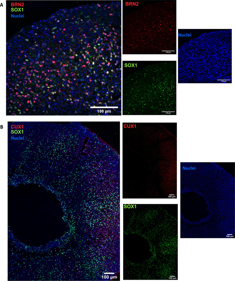
Neurons expressing layer II/III markers Cut Like Homeobox (CUX) 1 and BRN2 are present by day 150 (Fig. 21A and B). Presence of these late born neurons [1,5,9,11] underlie the capacity of the organoid system to recapitulate the cytoarchitecture of the developing cortex.
Fig. 21.
Long term culture of brain organoids allows upper layer specification. Sample images of immunostaining for superficial layer neuron markers (A) BRN2 and (B) CUX1 in cerebral organoids at day 150. Immunostainings were repeated on four brain organoids from one independent experiment. Scale bars: 100 μm.
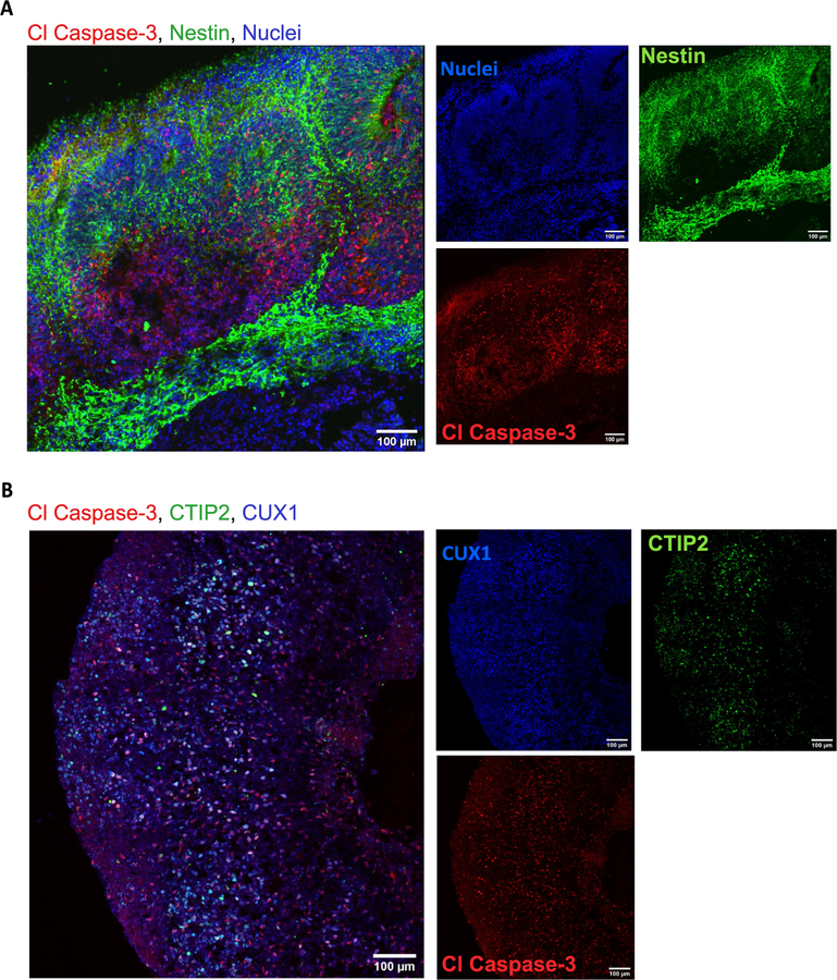
Finally, we analyzed the expression of the apoptosis marker cleaved Caspase 3 (ClC3). At day 60 and day 150, the presence of apoptosis is evident but the integrity of the cortical structures is maintained (Fig. 22A and 22B). Apoptosis is a key process during brain formation, controlling cellularity in the developing brain [25,26]. Work in human [27], mouse [26], and rat [28] brain samples shows high incidence of cell death during the development of the neocortex. As the overall architecture of the organoids was maintained, the observed cell death may be the result of the normal elimination of cells that takes place in the developing brain.
Fig. 22.
Immunostaining for apoptosis marker Caspase 3. A) Cells expressing Nestin and cleaved caspase 3 (Cl Caspase-3) at day 60 B) and day 150 show no structural compromise of the cortical architecture. CTIP2 (layer 5) and CUX1 (layer 2) markers of cortical layers are included for this time point. Immunostainings were repeated on four brain organoids from three independent experiments for day 60 and four brain organoids from one independent experiment for day 150.Scale bars: 100 μm. (B) stitched image.
Here we have shown that organoids cultured Spin∞ have the growth capacity and laminar organization previously reported in the literature [1,8,11,14]. Brain organoids grow above 3 mm in diameter. Immunohistochemistry analysis shows a distinct neural progenitor zone as well as positive markers for all cortical layers. Human NPC markers, as well as deep cortical and pan-neuronal markers can be identified in a structured manner and in the expected stages. Evaluation of the apoptotic marker ClC3 shows cell death in the core of the organoid as expected with no major compromise of the organoid integrity.
Our system demonstrated the following capabilities:
While the data shown here only include brain organoids grown up to day 150, we have successfully culture them over 200 days without the need to change motors, which demonstrates the increased motor life span of Spin∞ under high temperature and humidity conditions.
No contamination was detected even after long-term culture, which we suggest is due in part to the ability to autoclave the majority of Spin∞ components after assembly.
Supplementary Material
Table 3.
3D print components.
| Quantity | Part Name | Supplier |
|---|---|---|
| 1 | 12-Well Plate Lid (part B1) | Xometry (ULTEM 1010) |
| 1 | Base (part B2) | Xometry (ULTEM 1010) |
| 1 | Motor Shaft Gear (part B3) | Stratasys (ULTEM 1010) |
| 11 | Gear (part B4) | Stratasys (ULTEM 1010) |
| 6 | CW Paddle (part B5) | Stratasys (ULTEM 1010) |
| 6 | CCW Paddle (part B6) | Stratasys (ULTEM 1010) |
| 1 | Parylene Template for Gears | Stratasys (ABS) |
| 1 | Parylene Template for Paddles | Stratasys (ABS) |
| 1 | L298n Bridge Holder | Stratasys (ABS) |
Acknowledgments
We thank Dr. Bryan Millis (Vanderbilt Nikon Center for Excellence) for his technical support with image acquisition and processing, Dr. Jenny Schafer (Vanderbilt Cell Imaging Shared Resource) for support with light sheet imaging of embryoid bodies, and Dr. Rebecca Ihrie for helpful technical and scientific insight. We would like to thank members of the Gama and Lippmann Laboratories for helpful discussions and comments to the manuscript.
Funding
Funding was provided by a Ben Barres Early Career Acceleration Award from the Chan Zuckerberg Initiative (to ESL); NIH/NIGMS 1R35GM128915-01 (to VG); NIH/NCI 1R21 CA227483-01A1 (to VG); the Precision Medicine and Mental Health Initiative sponsored by the Vanderbilt Brain Institute (to VG and ESL); and NSF 1506717 (to LB). BJO was supported by the Vanderbilt Interdisciplinary Training Program in Alzheimer’s Disease (T32 AG058524). KMB was supported by the Training Program in Environmental Toxicology (T32 ES007028). Image acquisition and analysis were performed in part through the use of the Nikon Center of Excellence within the Vanderbilt Cell Imaging Shared Resource (supported by NIH grants CA68485, DK20593, DK58404, DK59637 and EY08126), Vanderbilt University Medical Center’s Translational Pathology Shared Resource supported by NCI/NIH Cancer Center Support Grant 2P30 CA068485-14, and the Vanderbilt Mouse Metabolic Phenotyping Center Grant 5U24DK059637-13.
Footnotes
Declaration of interest
The authors have no conflict of interest to declare.
Appendix A. Supplementary data
Supplementary data to this article can be found online at https://doi.org/10.1016/j.ohx.2019.e00084.
References
- [1].Lancaster MA, Renner M, Martin CA, Wenzel D, Bicknell LS, Hurles ME, Homfray T, Penninger JM, Jackson AP, Knoblich JA, Cerebral organoids model human brain development and microcephaly, Nature. 501 (2013) 373–379, 10.1038/nature12517. [DOI] [PMC free article] [PubMed] [Google Scholar]
- [2].Camp JG, Badsha F, Florio M, Kanton S, Gerber T, Wilsch-Bräuninger M, Lewitus E, Sykes A, Hevers W, Lancaster M, Knoblich JA, Lachmann R, Pääbo S, Huttner WB, Treutlein B, Human cerebral organoids recapitulate gene expression programs of fetal neocortex development, Proc. Natl. Acad. Sci 201520760 (2015), 10.1073/pnas.1520760112. [DOI] [PMC free article] [PubMed] [Google Scholar]
- [3].Quadrato Giorgia, Nguyen Tuan, Macosko Evan Z., Sherwood John L., Sung Min Yang Daniel R. Berger, Maria Natalie, Scholvin Jorg, Goldman Melissa, Kinney Justin P., Boyden Edward S., Lichtman Jeff W., Williams Ziv M., Steven A. McCarroll, Paola Arlotta, Cell diversity and network dynamics in photosensitive human brain organoids, Nature 545 (7652) (2017) 48–53, 10.1038/nature22047. [DOI] [PMC free article] [PubMed] [Google Scholar]
- [4].Subramanian L, Bershteyn M, Paredes MF, Kriegstein AR, Dynamic behaviour of human neuroepithelial cells in the developing forebrain, Nat. Commun 8 (2017) 14167, 10.1038/ncomms14167. [DOI] [PMC free article] [PubMed] [Google Scholar]
- [5].Pasßca AM, Sloan SA, Clarke LE, Tian Y, Makinson CD, Huber N, Kim CH, Park J-Y, O’Rourke NA, Nguyen KD, Smith SJ, Huguenard JR, Geschwind DH, Barres BA, Pasßca SP, Functional cortical neurons and astrocytes from human pluripotent stem cells in 3D culture, Nat Methods. 12 (2015) 671–678, 10.1038/nmeth.3415. [DOI] [PMC free article] [PubMed] [Google Scholar]
- [6].Pașca AM, Park JY, Shin HW, Qi Q, Revah O, Krasnoff R, O’Hara R, Willsey AJ, Palmer TD, Pașca SP, Human 3D cellular model of hypoxic brain injury of prematurity, Nat. Med 1 (2019), 10.1038/s41591-019-0436-0. [DOI] [PMC free article] [PubMed] [Google Scholar]
- [7].Kelava I, Lancaster MA, Stem Cell Models of Human Brain Development, Cell Stem Cell. 18 (2016) 736–748, 10.1016/j.stem.2016.05.022. [DOI] [PubMed] [Google Scholar]
- [8].Lancaster MA, Knoblich JA, Generation of cerebral organoids from human pluripotent stem cells, Nat. Protoc 9 (2014) 2329–2340, 10.1038/nprot.2014.158. [DOI] [PMC free article] [PubMed] [Google Scholar]
- [9].Kadoshima T, Sakaguchi H, Nakano T, Soen M, Ando S, Eiraku M, Sasai Y, Self-organization of axial polarity, inside-out layer pattern, and speciesspecific progenitor dynamics in human ES cell-derived neocortex, Proc. Natl. Acad. Sci 110 (2013) 20284–20289, 10.1073/pnas.1315710110. [DOI] [PMC free article] [PubMed] [Google Scholar]
- [10].Lancaster MA, Corsini NS, Wolfinger S, Gustafson EH, Phillips AW, Burkard TR, Otani T, Livesey FJ, Knoblich JA, Guided self-organization and cortical plate formation in human brain organoids, Nat. Publ. Gr 35 (2017), 10.1038/nbt.3906. [DOI] [PMC free article] [PubMed] [Google Scholar]
- [11].Qian X, Nguyen HN, Song MM, Hadiono C, Ogden SC, Hammack C, Yao B, Hamersky GR, Jacob F, Zhong C, Yoon KJ, Jeang W, Lin L, Li Y, Thakor J, Berg DA, Zhang C, Kang E, Chickering M, Nauen D, Ho CY, Wen Z, Christian KM, Shi PY, Maher BJ, Wu H, Jin P, Tang H, Song H, Ming GL, Brain-Region-Specific Organoids Using Mini-bioreactors for Modeling ZIKV Exposure, Cell. 165 (2016) 1238–1254, 10.1016/j.cell.2016.04.032. [DOI] [PMC free article] [PubMed] [Google Scholar]
- [12].Qian X, Jacob F, Song MM, Nguyen HN, Song H, Ming GL, Generation of human brain region–specific organoids using a miniaturized spinning bioreactor, Nat. Protoc 13 (2018) 565–580, 10.1038/nprot.2017.152. [DOI] [PMC free article] [PubMed] [Google Scholar]
- [13].Tan CP, Craighead HG, Surface engineering and patterning using parylene for biological applications, Materials (Basel). 3 (2010) 1803–1832, 10.3390/ma3031803. [DOI] [Google Scholar]
- [14].Sutcliffe M, Lancaster MA, A Simple Method of Generating 3D Brain Organoids Using Standard Laboratory Equipment, Humana Press (2017) 1–12, 10.1007/7651_2017_2. [DOI] [PubMed] [Google Scholar]
- [15].Marton RM, Miura Y, Sloan SA, Li Q, Revah O, Levy RJ, Huguenard JR, Pașca SP, Differentiation and maturation of oligodendrocytes in human three-dimensional neural cultures, Nat. Neurosci 22 (2019) 484–491, 10.1038/s41593-018-0316-9. [DOI] [PMC free article] [PubMed] [Google Scholar]
- [16].Yoon SJ, Elahi LS, Pașca AM, Marton RM, Gordon A, Revah O, Miura Y, Walczak EM, Holdgate GM, Fan HC, Huguenard JR, Geschwind DH, Pașca SP, Reliability of human cortical organoid generation, Nat. Methods 16 (2019) 75–78, 10.1038/s41592-018-0255-0. [DOI] [PMC free article] [PubMed] [Google Scholar]
- [17].Zhang S-C, Wernig M, Duncan ID, Brüstle O, Thomson JA, In vitro differentiation of transplantable neural precursors from human embryonic stem cells, Nat. Biotechnol 19 (2001) 1129–1133, 10.1038/nbt1201-1129. [DOI] [PubMed] [Google Scholar]
- [18].Gerrard L, Rodgers L, Cui W, Differentiation of human embryonic stem cells to neural lineages in adherent culture by blocking bone morphogenetic protein signaling, Stem Cells. 23 (2005) 1234–1241, 10.1634/stemcells.2005-0110. [DOI] [PubMed] [Google Scholar]
- [19].Hříbková H, Grabiec M, Klemová D, Slaninová I, Sun Y-M, Five steps to form neural rosettes: structure and function, J. Cell Sci 131 (2018) jcs206896, 10.1242/jcs.206896. [DOI] [PubMed] [Google Scholar]
- [20].Elkabetz Y, Panagiotakos G, Al Shamy G, Socci ND, Tabar V, Studer L, Human ES cell-derived neural rosettes reveal a functionally distinct early neural stem cell stage, Genes Dev. 22 (2008) 152–165, 10.1101/gad.1616208. [DOI] [PMC free article] [PubMed] [Google Scholar]
- [21].Kriegstein A, Alvarez-Buylla A, The Glial Nature of Embryonic and Adult Neural Stem Cells, Annu. Rev. Neurosci 32 (2009) 149–184, 10.1146/annurev.neuro.051508.135600. [DOI] [PMC free article] [PubMed] [Google Scholar]
- [22].Hevner RF, Shi L, Justice N, Hsueh YP, Sheng M, Smiga S, Bulfone A, Goffinet AM, Campagnoni AT, Rubenstein JL, Tbr1 regulates differentiation of the preplate and layer 6, Neuron. 29 (2001) 353–366, 10.1016/S0896-6273(01)00211-2. [DOI] [PubMed] [Google Scholar]
- [23].Shafit-Zagardo B, Kalcheva N, Making sense of the multiple MAP-2 transcripts and their role in the neuron, Mol. Neurobiol 16 (1998) 149–162, 10.1007/BF02740642. [DOI] [PubMed] [Google Scholar]
- [24].Frotscher M, Cajal-Retzius cells, Reelin, and the formation of layers, Curr. Opin. Neurobiol 8 (1998) 570–575, 10.1016/S0959-4388(98)80082-2. [DOI] [PubMed] [Google Scholar]
- [25].Kuan C-Y, Roth KA, Flavell RA, Rakic P, Mechanisms of programmed cell death in the developing brain, Trends Neurosci. 23 (2000) 291–297, 10.1016/S0166-2236(00)01581-2. [DOI] [PubMed] [Google Scholar]
- [26].Nonomura K, Yamaguchi Y, Hamachi M, Koike M, Uchiyama Y, Nakazato K, Mochizuki A, Sakaue-Sawano A, Miyawaki A, Yoshida H, Kuida K, Miura M, Local apoptosis modulates early mammalian brain development through the elimination of morphogen-producing cells, Dev. Cell 27 (2013) 621–634, 10.1016/j.devcel.2013.11.015. [DOI] [PubMed] [Google Scholar]
- [27].Anlar B, Atilla P, Cakar N, Tombakoglu M, Bulun A, Apoptosis in the developing human brain: a preliminary study of the frontal region, Early Hum. Dev 71 (2003) 53–60, 10.1016/S0378-3782(02)00116-0. [DOI] [PubMed] [Google Scholar]
- [28].White LD, Barone S, Qualitative and quantitative estimates of apoptosis from birth to senescence in the rat brain, Cell Death Differ. 8 (2001) 345–356, 10.1038/sj.cdd.4400816. [DOI] [PubMed] [Google Scholar]
Associated Data
This section collects any data citations, data availability statements, or supplementary materials included in this article.


