Abstract
The synthetic peptide RAD16-II has shown promise in tissue engineering and drug delivery. It has been studied as a vehicle for cell delivery and controlled release of IGF-1 to repair infarcted cardiac tissue, and as a scaffold to promote capillary formation for an in vitro model of angiogenesis. The structure of RAD16-II is hierarchical, with monomers forming long β-sheets that pair together to form filaments; filaments form bundles approximately 30–60 nm in diameter; branching networks of filament bundles form macroscopic gels. We investigate the mechanics of shearing between the two β-sheets constituting one filament, and between cohered filaments of RAD16-II. This shear loading is found in filament bundle bending or in tensile loading of fibers composed of partial-length filaments. Molecular dynamics simulations show that time to failure is a stochastic function of applied shear stress, and that for a given loading time behavior is elastic for sufficiently small shear loads. We propose a coarse-grained model based on Langevin dynamics that matches molecular dynamics results and facilities extending simulations in space and time. The model treats a filament as an elastic string of particles, each having potential energy that is a periodic function of its position relative to the neighboring filament. With insight from these simulations, we discuss strategies for strengthening RAD16-II and similar materials.
1. Introduction
The mechanical properties of bundled filamentous proteins confer unique functionality to many important materials in biology and engineering. Filament bundles enable the extraordinary toughness of collagen [1], the frequency-selective transduction of sound waves by stereocilia [2], and the extension of filopodia by a migrating cell [3]. In all of these cases the fibers serve a structural role, and their mechanical properties are of great importance. Scaffold materials used as three-dimensional substrates for tissue engineering frequently have a similar structure. The scaffold’s stiffness influences cell viability, migration, and differentiation, and the ability to modulate mechanical properties is therefore highly desirable. One important determinant of the properties of a filament bundle is the shear response between adjacent filaments, which may be modeled as elastic [4] or inelastic [1]. The elastic models often used for filaments are appropriate for filament bundles when energy loss due to interfilament slippage is negligible.
We introduce the term “amyloid-forming peptides” (AFP’s, for brevity) to describe one class of materials that form filament bundles. Many synthetic AFP’s now exist, some that copy or mimic a segment of a natural protein [5–7] and some that do not [8, 9]. Their key characteristic is the formation of filaments with a cross-β structure, wherein monomers are aligned normal to the filament axis in either parallel [10] or antiparallel [11] fashion.
Many AFP’s reviewed by Zhang [12] possess a self-complementary pattern of charged residues wherein (1) the juxtaposition of oppositely charged side chains energetically favors the formation of β-sheets, and (2) the primary sequence alternates between hydrophobic and hydrophilic residues, resulting in a β-sheet with one side composed of hydrophobic side chains and the other of ionizable side chains. In the present study we examine the self-complementary peptide Ac-[RARADADA]2-Am, called RAD16-II. RAD16-II forms a tape-like filament of two β-sheets with a hydrophobic core (Figure 1). Each β-sheet has a hydrophobic surface of alanine side chains while charged arginine and aspartic acid side chains form the opposing hydrophilic surface. An antiparallel β-sheet is thought to be favored, as it has a lower energy than a parallel formation, which would juxtapose like charges [13]. At concentrations on the order of 0.1%, RAD16-II forms a macroscopic gel. These gels are networks of filament bundles 30–40 nm in diameter [14], or 10–20 nm when dehydrated [15], each large enough to include many individual filaments.
Figure 1.
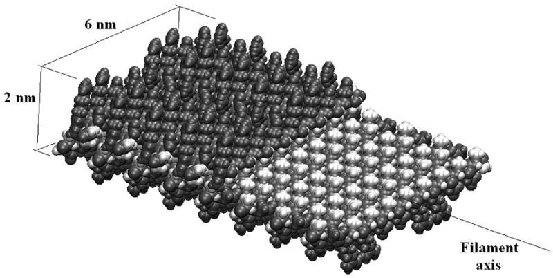
A filament of RAD16-II comprises two β-sheets, each with a hydrophobic surface of alanine side chains oriented toward the filament center, and an outer hydrophilic surface of arginine and aspartic acid side chains. A filament has a roughly rectangular cross-section. Here the upper β-sheet is cut away to show the hydrophobic core.
Self-assembly of individual filaments into fibers and gels is initiated when repulsive charges are either neutralized by changing pH or shielded by increasing ionic strength. The forces driving various AFP’s assembly into stable gels have been attributed to salt bridges between charged residues [16], interaction of hydrophobic residues [16–18], polar organization due to amphiphilicity [19], and hydrogen bonding between glutamine residues [20]. One or more of these mechanisms may be at work in any given peptide. The fibrillar β-sheet structure tends to make these materials tolerant to extremes of temperature and pH [16], resistant to enzymatic activity [9, 16], and congophillic [7]. Many have noted the structural similarity of synthetic amyloid-forming peptides to naturally occurring A-β protein [7, 18], pathogenic polyglutamines [9], and silk fibroin [16], all proteins of extraordinary stability.
RAD16-II and other self-complimentary AFP’s show promise for applications in tissue engineering and drug delivery. For cardiac repair, injectable RAD16-II has been proposed as a vehicle for cell delivery and a scaffold for controlled release of tethered IGF-1 [21, 22]. RAD16-II also provides a model for studying angiogenesis, as human microvascular endothelial cells embedded in RAD16-II gels give rise to a 3-D capillary-like network in vitro [23]. Other self-complementary AFP’s used in tissue engineering research include RAD16-I (Ac-[RADA] 4-Am) [24] and KLD12 (Ac-[KLDL] 3-Am) [25, 26].
For some applications the utility of RAD16-II and similar materials may be restricted by their low stiffness or their tendency to fracture at relatively small strains. Gel stiffness may be increased over a certain range by raising peptide concentration, but this approach is limited by peptide solubility. Some previous attempts have been made to increase the stiffness of various AFP gels. Introducing cross-links (biotin-streptavidin [27], or lysine-glutamine [9]) does not increase mechanical integrity appreciably, but materials of varied primary structure do exhibit a wide range (170–3500 Pa) of stiffness [28]. These observations suggest that the stiffness of AFP gels is not limited primarily by slippage between filament bundles, which cross-linking should restrict, but by the stiffness of the filament bundles themselves. While β-sheet filaments have a high elastic modulus on the order of 10 GPa in tension [13], filament bundles may have little resistance to bending if slipping occurs between filaments. Such slippage reportedly occurs in bundles of carbon nanotubes [29], but this phenomenon had not yet been postulated for bundled amyloid filaments such as RAD16-II.
In this study we use simulations to probe the mechanical properties of RAD16-II filaments and inter-filament bonds. RAD16-II is selected for its simple, straight filament structure and its promise as a biomaterial. We perform molecular dynamics (MD) simulations on all-atom representations of one- and two-filament segments to observe the mechanics of elastic strain and slippage between β-sheets. Computational expense limits MD simulations to nanoseconds of duration and nanometers of filament length, therefore we introduce a coarse-grained model of inter-filament shear to interpret and extend the MD results.
2. Molecular dynamics simulations
2.1. Methods
CHARMM version 32b was used to conduct all-atom MD simulations of the synthetic peptide Ac-[RARADADA]2-Am. The CHARMM version 27 force field [30] was used to calculate the force acting on each atom, and the classical equations of motion were numerically integrated over discrete time steps to obtain trajectories. A cutoff of 16 Å was applied to nonbonded electrostatic interactions. The Nose-Hoover thermostat [31] was used to allow sampling from the canonical ensemble, and the GBSW implicit solvent model [32] was used to approximate energetic effects of water. GBSW has been shown to agree well with Poisson-Boltzmann solvers [33] and with experimental observables [34].
While it has not been experimentally determined whether RAD16-II β-sheets have parallel or antiparallel alignment, previous simulations have shown that the antiparallel structure has significantly lower energy [13]. To make antiparallel β-sheets, we assigned dihedral angles consistent with a β-sheet to the peptide backbone, and positioned one peptide every 4.8 Å. A double-layer filament was created by positioning two such β-sheets with their hydrophobic surfaces in contact. A two-filament (two double-layers) structure was created by duplicating this filament and positioning it beside the original, with the charged surfaces in contact. Each system was minimized with 200 steps of the steepest descent algorithm followed by 2000 steps of adopted basis Newton-Raphson and equilibrated at 300 °C for 500 ps. The final coordinates and velocities of the equilibrated structures were used as starting conditions for simulations. When simulations were performed in triplicate, a second and third set of initial conditions were generated by equilibrating for a further 50 ps and 100 ps.
Shear between surfaces was created by applying to each α-carbon in one β-sheet a constant force along the filament axis, and applying an opposite force to the α-carbons of another sheet (Figure 2). Because the moment from these forces would give rise to a rotation, a small force normal to the filament axis was applied to the α-carbons of the first and last two peptides of each loaded β-sheet, such that the net moment was zero. In double-filament simulations the shear force is applied to the two outer β-sheets while the two inner β-sheets are not subjected to any external force, such that all three bonding surfaces are stressed (Figure 2B). Displacement between the backbones of two β-sheets was calculated as the difference in mean position of the α-carbon atoms of each. Displacement was converted to shear strain by dividing by 17.5 Å, the width of one period in equilibrated, stacked filaments.
Figure 2.
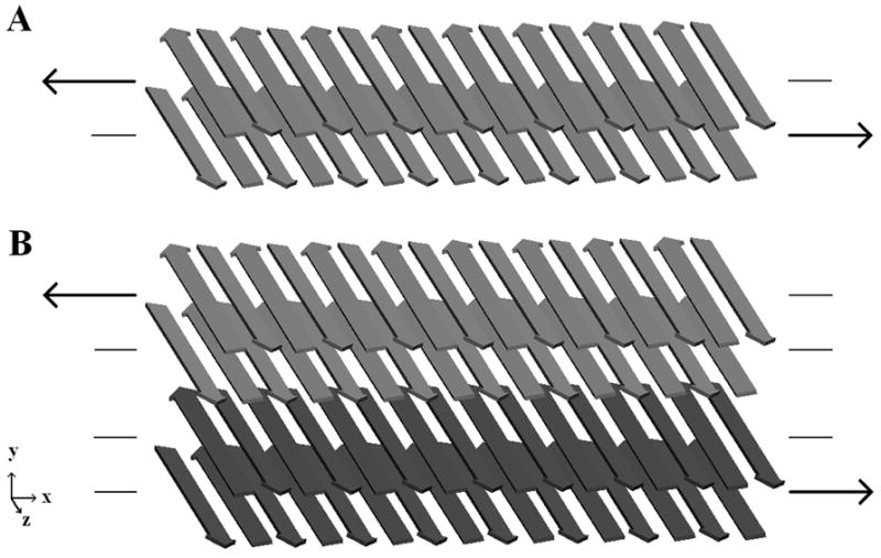
Shear loading schemes for one (A) or two (B) double-layered filaments are shown. (A) Shear stress is applied over the hydrophobic surface at the core of a single filament. (B) Shear stress is applied over the hydrophobic core of each filament and the charged surface between the filaments. In each case a constant force is applied to the α-carbons in one β-sheet, and an opposite force to the α-carbons of another β-sheet. Forces are directed along the filament axis.
2.2. Linear elastic behavior
When varied levels of shear stress were applied to two stacked filaments (Figure 2B), a linear elastic regime with a shear modulus of 1.8 GPa was evident for shear stresses below 83 MPa and engineering shear strains less than about 5%. At these low levels of stress, strain was elastically recovered within a few picoseconds after the shear stress was removed. Strain softening was observed for shear loads of 125 to 208 MPa, with near-complete elastic recovery after the load was removed. At the higher end of this range, trajectories showed a slight drift following the initial abrupt change in displacement, suggesting that failure may still occur at these stresses if simulation times were extended. When these levels of shear load were removed, an initial abrupt strain recovery was followed by a drift toward zero displacement.
2.3. Atomistic description of shear failure
With a load of 250 MPa, the two hydrophobic surfaces in the stacked filament pair failed during the 40-ps interval (Figure 3), while the charged surface did not slip. To understand the nature of this failure, note in Figure 1 the makeup of the hydrophobic surface. The methyl side chains of alanine residues, shown in white, form a regular rectangular array. Alanine side chains from the opposite β-sheet fill the interstices of this array to make a regular pattern with each side chain occupying a space corresponding to a minimum of free energy. In order for slippage to occur between the two β-sheets, each methyl group must jump from one open space into the next.
Figure 3.
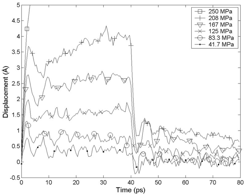
Under small shear loads the shear deformation of RAD16-II filaments (loaded as in Figure 2B) is elastic. Under 250 MPa of applied shear, the filaments slip irreversibly within a few ps.
Figure 5 shows the trajectory of one of these methyl groups relative to nearby atoms on the opposing surface. The side chain moved in discrete jumps of about 5 Å, corresponding to the spacing between β-strands. By choosing a threshold position and measuring the time at which it is crossed by each side chain, we could discern the pattern of failure initiation and propagation on the hydrophobic intrafilament surface (Figure 6). In this simulation, failure began near the center of the right edge and propagated laterally along a β-strand and longitudinally to neighboring β-strands.
Figure 5.
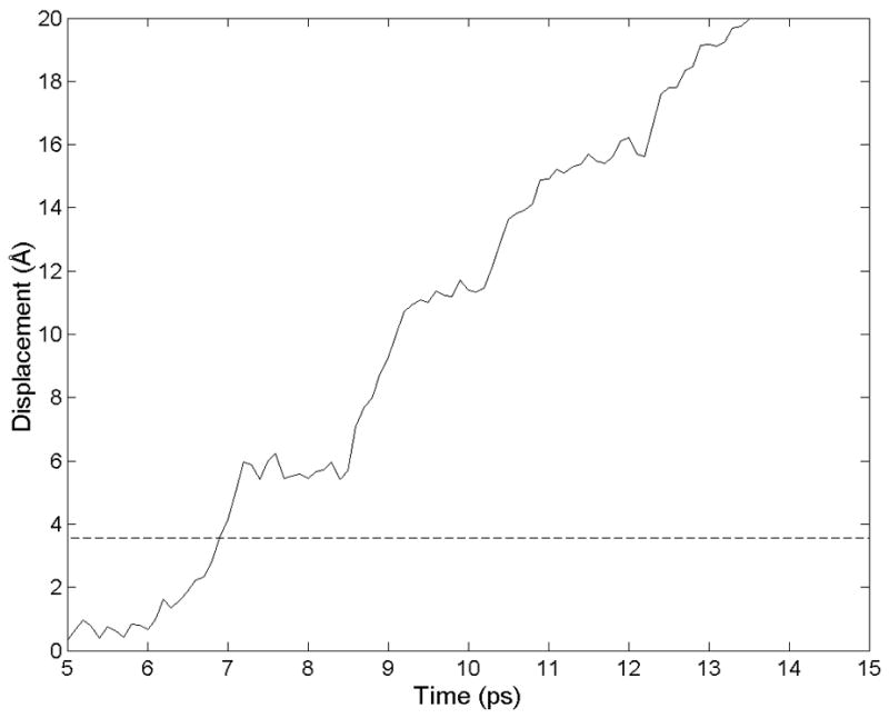
The trajectory of the methyl carbon in an alanine side chain is shown as a the hydrophobic core of an RAD16-II filament is forced to slip. The discrete jumps indicate energy minima with a spacing that corresponds to the 4.8 Ǻ between β-strands.
Figure 6.
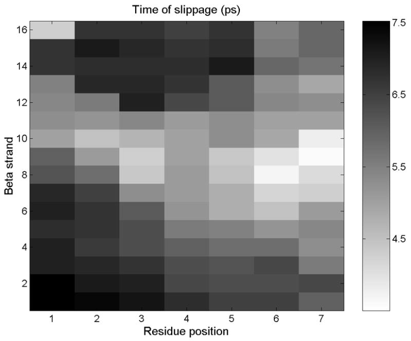
The hydrophobic surface of a filament of RAD16-II is represented, with each pixel representing one alanine side chain. Failure initiates at the white-colored points, then propagates laterally and longitudinally to the rest of the surface.
2.4. Time to failure
The simulation results discussed in the previous section suggest that in bundles of RAD16-II filaments, the hydrophobic surfaces are weaker than hydrophilic surfaces. This is subject to the caveat that our modeled filaments are well aligned with bound surfaces in full contact and no incorporated water molecules, while the actual geometry may be somewhat more complicated. Based on the results above we turn our attention to the apparently weaker hydrophobic surfaces by applying a shear load as demonstrated in Figure 2A.
Over a 1-ns window of simulation time, we observed failure of the hydrophobic surface for shear loads ≥200 MPa (Figure 7). The mean time at which slippage occurs decreased with increasing shear stress. In all three simulations at 183 MPa, failure did not occur within 1 ns. On a node of 8 CPUs, simulations have a rate of about 20 ps of per hour.
Figure 7.
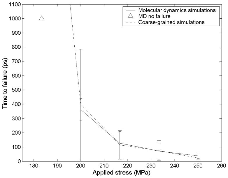
The time from when a load is first applied to when failure occurs is plotted against the applied shear stress for both MD simulations (n=3) and coarse-grained simulations (n=100). The triangle indicates MD simulations terminated before failure occurred (n=3). At 183 MPa the coarse-grained simulations had a mean failure time of 2935 ps, standard deviation 2552 ps.
3. Coarse-grained model of filament slippage
While longer filaments and longer MD simulation times would help to illuminate the behavior of RAD16-II filaments, the computational expense quickly becomes prohibitive. To gain insights into these computationally expensive regimes of material behavior, we developed a coarse-grained model of filament slippage.
3.1. The model
Here we introduce a mechanistic model to describe sliding between two noncovalently bound filaments. For simplicity we rigidly fix one filament and consider only the motions of its partner. The moving filament is assumed to be a linear chain of identical units, each unit represented as a single particle. We assume particles move only along the filament axis, reducing the model to one dimension. Using Newton’s classical equations of motion would neglect fluctuations in energy introduced by the surrounding environment. Instead, to simulate the canonical ensemble we use Langevin dynamics as a thermostat:
| (1) |
| (2) |
The variable xi(t) represents position, vi(t) velocity, and mi the mass of particle i. α is a friction constant with units of [mass/time]. The thermal force R(t) is assigned a Gaussian distribution with a mean of <R(t)> = 0 and covariance <R(t)R(t′)> = 2αkBTδ(t). When discretized into time steps of length Δt, the covariance becomes <R(t)R(t′)> = 2αkBT/Δt. Fi(t) represents the force acting on the particle. This includes contributions from the rest of the filament, the neighboring filament, and an externally applied force. In our long one-dimensional chain, particles have an equilibrium spacing distance of l. We assume linear elasticity such that the energy of the bond of particle i with particles i−1 and i+1 is Uf, i = κf ((xi−xi−1−l)2+(xi+1−xi−l)2)/2, where κf is filament stiffness. κf, is equal to AEf/l, where A is cross-sectional area and Ef is the axial Young’s modulus of the filament. The force exerted on displaced particle i is the negative of the spatial derivative of energy, Ff, i = −∂Uf,i/∂xi.
Due to the repeating filament structure, energetic interactions of each particle with the rigid, bound filament are assumed periodic in x with a period of l. The peaks in this energy landscape might correspond to points of steric hindrance and high van der Waals energy, unfavorable electrostatic interactions or breakage of favorable electrostatic interactions, or reduced entropy due to motion constraints. Specifically, we define the energy Ub,i of the ith particle as a sinusoid of period l. (See section 3.3 for a discussion of selecting the periodic function.) Twice its amplitude gives the transition energy Ua between minima, and a Taylor expansion about the minimum gives a local stiffness of κb=2π2Ua/l2. The resulting force on particle i is Fb,i = −∂Ub,i/∂xi. Additionally, each particle is subjected to an externally applied force Pi, with energy UP,i = xiPi. The force Pi may arise from the shear stress transmitted from surrounding filaments in a filament bundle, and for uniform shear loading we assume constant Pi = P uniformly for all particles. The total potential energy of particle i is Ui = Uf,i + Ub,i + UP,i, and the force on particle i is Fi = Ff,i + Fb,i + P.
We nondimensionalize the equations of motion, taking as characteristic values mass m, length l, and the thermal energy setpoint kBTo. This gives rise to dimensionless variables x* = x/l, t* = (kBTo/ml2)1/2t, and v* = dx*/dt* = (m/kBTo)1/2dx/dt. From the governing equations, four dimensionless parameters arise:
| (3) |
ΠP, Πf, Πt, and Πα may be considered dimensionless expressions of external force per particle, filament stiffness, transition state energy, and strength of coupling to the thermal bath (or viscosity), respectively. Defining a dimensionless thermal force R* whose mean is zero and whose variance is 2Πα/Δt* we can now rewrite the governing equations in dimensionless form.
| (4) |
| (5) |
A script was written in C to numerically integrate Eqs. (4) and (5) using the leapfrog method. All parameters could be arbitrarily specified, including the number of particles and the time step. As an initial condition all particles were evenly spaced and positioned at a local energy minimum. Unless otherwise specified we use 16 particles and a time step of 10−4. Select simulations repeated with a time step 10−5 yielded nearly identical results (not shown).
3.2. Time to failure
Nondimensional results were applied to RAD16-II using parameters consistent with the MD simulations: β-strand spacing l = 4.8 Å, thermal energy kBT = 4.14 × 10⁻²¹ J/K, and RAD16-II monomer mass m=1.713 kDa. In MD simulations, a friction constant of γ = 5 ps−1 (the fbeta parameter in CHARMM) was found to produce particle velocities whose autocorrelation had a decay time similar to that produced with the Nosé-Hoover thermostat in MD simulations (results not shown). Correspondingly, a viscous constant of α =γ/m = 1.42 × 10⁻¹¹ kg/ps was used in the coarse-grained model. Applied shear forces were exactly specified in the range of 576–720 pN per particle. Of the four dimensionless parameters, two are specified by the values above (ΠP = 61.3 to 83.4, and Πα = 63), leaving only Πf and Πb for tuning. These were varied and the quality of fit was manually checked to iteratively obtain a satisfactory fit.
Good agreement with MD results is obtained using Πf = 30 and Πb = 95 (Figure 7). Let us ask whether these values are physically reasonable. From the simulations described in Figure 3 we obtained a shear modulus of 1.8 GPa for strains < 4%, and from this we estimate the stiffness of the bond between β-sheets. With shear occurring between β-sheets whose backbones are about 10 Ǻ apart, and a sheared area of 4.8 Ǻ × 60 Ǻ per β-strand, κb is 5.2 N/m, corresponding to a value of Πb = 46, in order-of-magnitude agreement with our fitted value. Park et al. estimate that a two-β-sheet filament exerts 1.6±0.6 × 10⁻⁷ N per unit axial strain; for one β-sheet over one period of 4.8 Ǻ this corresponds to a stiffness of 167 N/m, or a nondimenesional stiffness of 9300. Πf, the stiffness between alanine side chains on adjacent β-strands, is much lower since the displacement can occur due to side chain flexing or rotation of the β-strand in addition to stretching of the backbone. Thus the values fitted values of Πf and Πb appear to be reasonable. All parameters defining the coarse-grained model are listed in Table 1.
Table 1.
Dimensionless parameters of the coarse-grained model of interfilament shear.
| Parameter | Value | Description |
|---|---|---|
| ΠP | 61.3–83.4 | Applied shear |
| Πf | 30 | Tensile stiffness |
| Πb | 95 | Shear stiffness between bound β-sheets |
| Πα | 63 | Strength of coupling to thermal bath |
In addition to accurately predicting mean time to failure, the behavior of coarse-grained model simulations was generally consistent with that of MD simulations of slippage. The center-of-mass trajectories exhibited discrete jumps in position analogous to the jumps in shear strain observed in MD simulations and shown in Figure 5.
Plotting the mean time to failure against the applied stress on a log-log scale shows a linear trend (Figure 8), regardless of chain length. This power law is consistent with the behavior of a single energetic trap observed by Evans et al. [35, 36]. For a given level of applied stress, time to failure also varies with the number of particles in the chain via a power law relationship. Intuitively, we understand that time to initiation of failure decreases as filament length increases, since the longer filament provides more sites at which initiation might occur. A best fit to a double-power law relationship gives the parameters in Equation (6) and the trend lines in Figure 8 (r2=0.935).
Figure 8.
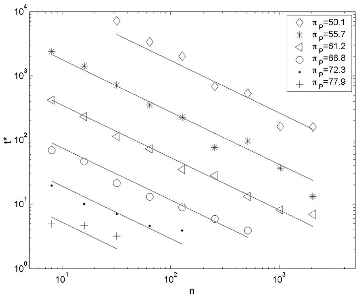
In coarse-grained simulations, a power law was found to relate time to initial failure to applied load and to the number of particles simulated. The lines show a global best-fit described by Equation (6), with r2=0.935.
| (6) |
The first factor in this equation has the form proposed by Evans et al., while the second factor is new and purely empirical.
With the fitted parameters, simulations are stable and consistent with a dimensionless time step as large as 0.01. With this time step, simulations run at about 300 dimensionless time units (or 4 ns) per hour, about 1500x faster than the corresponding MD simulations on a per-CPU basis.
We examined time-to-failure results’ sensitivity to the model parameters. Results were most sensitive to changes in Πb, with as much as an 8-fold increase in average failure time resulting from a 10% increase in Πb. This parameter determines the height of the energy barrier, so its importance is not unexpected. A 2-fold increase in filament stiffness Πf increased average failure times as much as 5-fold, and a 2-fold increase in viscosity Πα approximately doubled average failure times.
3.3. Contour of the energy landscape
While a sinusoidal energy landscape was used to produce the above results, the model behavior is similar with to that obtained with other suitable periodic functions. Five energy landscape functions were examined (Figure 9A). We designated these as the triangle wave (V), the sinusoid (S), the parabola with sharp cusps at the energy maxima (U), and parabolas whose cusps are smoothed with either 3rd- or 4th-order polynomials (3o) or (4o). 3o is undesirable as it leaves an abrupt, flat curve over the cusp compared to the smoother 4o. V is unique also in that its force is discontinuous at both the energy minima and the energy maxima. U and 4o gave results very similar to the sinusoid S when the zero-force transition energy of the functions (as opposed to the stiffness about the energy minima) was matched (Figure 9B).
Figure 9.
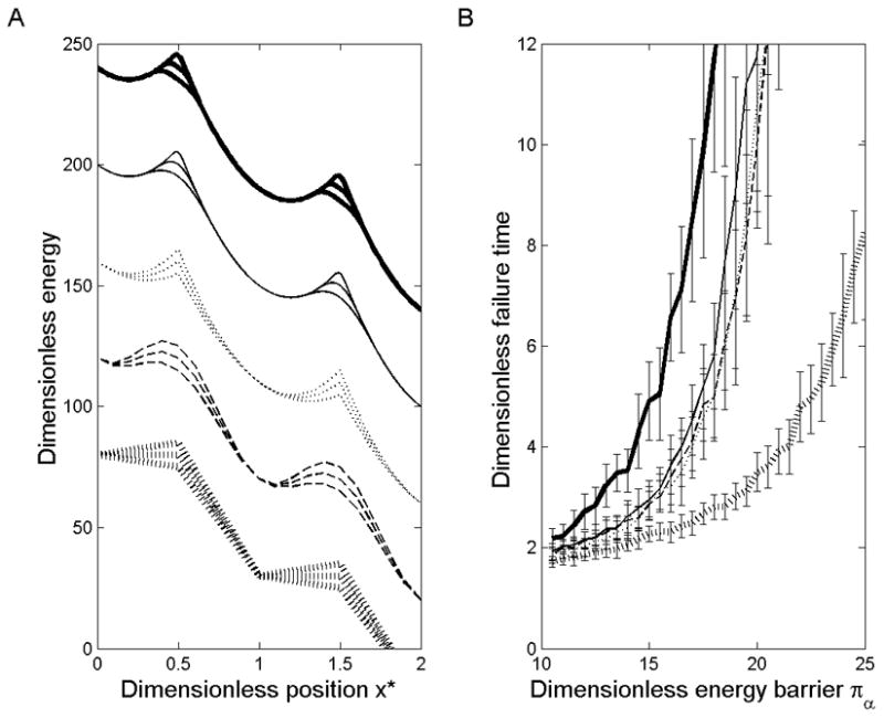
(A) Five periodic energy functions are shown, with arbitrary positioning on the y-axis. Each is shown with dimensionless energy barrier Πb set to 30, 25, and 20 for illustration, all under a dimensionless load of ΠP = 50. From top to bottom these are 3o, 4o, U, S, and V, as defined in the text. (B) Dimensionless time to failure is plotted from simulations performed with a system of 16 particles using each energy function over a range of values for Πb Each line style matches that of the function in (A) used to generate it.
4. Discussion
Modeling has proven useful in understanding the mechanical behavior of protein filament bundles. For example, Bathe et al. have introduced a model to describe actin bundles formed from a host of actin-binding proteins (ABP’s), based on the shear stiffness and spacing of these ABP’s and the bundle diameter and length ([37]). Buehler has investigated the properties of collagen fibers using a coarse-grained model that incorporates the failure strength of slippage between molecules, as obtained by MD [1]. We find that unlike Bathe’s actin bundles, filaments of RAD16-II and other AFP’s require consideration of interfilament slippage. Buehler’s approach uses MD simulations to estimate a fixed failure strength, but the short time scales of MD simulations, generally ns or μs, are expected to result in unusually high strengths [38]. To our knowledge, the time dependence of failure strength has not been taken into account for protein filament bundles until the present study.
Many elements of our coarse-grained model appear in the literature. The Rouse model, for example, represents a polymeric filament as a chain of particles connected by springs and subjected to Langevin forces [39]. In a general sense, our model is also similar to all-atom (MD) or coarse-grained simulations using Langevin dynamics (e.g. [40]). All these approaches include discrete particles moving in a defined energy landscape according to Langevin dynamics. Our model differs from these, though, in its one-dimensionality. The model proposed by Bathe et al. ([37]) similarly neglects deflection in directions normal to the filament axis but provides only a static solution of the shearing of filament bundles wherein no slippage occurs. Thus while our coarse-grained model relies on methods well established in the literature, it has combined these in a new way to model the deformation of sheared bundles of aligned filament that undergo slippage.
Park et al. [13] used thermal mode analysis and normal mode analysis to determine that the tensile stiffness of RAD16-II at 1.6±0.6 × 10⁻⁷ N (where stiffness is unusually defined as resisting force per unit strain.) For one filament’s cross-sectional area of about 17.5 Ǻ × 60 Ǻ, this gives a Young’s modulus of 9.5–21 GPa. In an isotropic, incompressible material the shear modulus would be one third of this value, 3.2–7.0 GPa. We found the shear modulus between tightly stacked filaments to be only 1.8 GPa, and the inclusion of water-filled voids might lower the modulus and increase the anisotropy even further. Given the inherently anisotropic structure of filament bundles, this is not a surprising result. Anisotropy has been documented for other bundled filaments such as microtubules [41] and single-walled carbon nanotube ropes [42].
While MD simulation is suitable for obtaining the elastic properties of a system the size of ours (7500 to 15,000 atoms), obtaining failure data is a greater challenge. Failure time is a stochastic function of the applied load; or conversely, failure strength is a function of observation time. For results of MD simulations--generally nanoseconds in duration--to be applied to ordinary time scales, this time dependence must be accounted for. We have done so in two ways. First, using a coarse-grained model allows us to run more simulations and to extend them to longer times than would be feasible using MD. Second, we have fit the simulation results with Eq. 6 to predict behavior at time scales unattainable even with coarse-graining.
At each of these steps, efficiency is obtained at the expense of detailed information. MD simulations comprising 7500 atoms, each with independent 3-dimensional motion, are mimicked by a coarse-grained model of 16 particles moving in one dimension. Fitting an equation to the failure times obtained from simulations reduces the system further such that no information on individual particle motion remains. This approach assumes that the failure mechanism on a time scale of seconds is the same mechanism as occurs in nanoseconds, a postulation that can only be verified when model predictions are confirmed by experiment. Such coarse models are necessary to bridge the gap between the atomistic detail obtainable only in MD simulations and the much larger time and length scales accessible by experimental techniques.
A previous analysis by Leon et al. [43] modeled the AFP gel EFK8 as a cellular solid composed of isotropic elastic beams which deform primarily in bending. This analysis found the bulk properties of EFK8 consistent with a filament Young’s modulus of ~1 MPa, whereas Park et al. [13] found the axial Young’s modulus of RAD16-II filaments to be about 1000x this value. The results from the present study allow us to explore and shed some light on this discrepancy. Three potential explanations are as follow:
Anisotropy makes the filament bundles more compliant in shear such that bending is no longer the dominant mode of deformation.
Adhesion between filaments is sufficiently weak that slippage occurs in the filament bundle to relieve stress even for small strains at the bulk level.
Imperfections or void spaces within the filament bundles are sufficiently common that filament bundles cannot be modeled as a monolithic beam.
The following analysis suggests that explanations (1) and (2) are unlikely, while explanation (3) is plausible. The prevalence of void spaces or packing imperfections will remain a subject for future studies.
The modeling approach of Gibson and Ashby [44] for mechanical analysis of cellular solids has been successfully applied to a wide range of porous materials, including protein filament networks [43, 45]. Given the Young’s modulus of the material’s solid fraction, this modeling approach enables a rough estimate of bulk Young’s modulus by analyzing a unit cell with typical microstructural dimensions. Employing the cellular solids model, we consider a unit cell wherein a filament bundle of RAD16-II is loaded by intersecting fibers as in Figure 10A. Figure 10B shows the idealized loading condition, where moments and shear are resisted at both end points and a load P is applied at the filament bundle’s center. At the inflection point halfway between the end and the center, the moment falls to zero. This enables us to model each segment of the filament bundle as a cantilevered beam with a lateral applied load of P/2 at the tip (Figure 10C). Elementary beam theory predicts that
Figure 10.
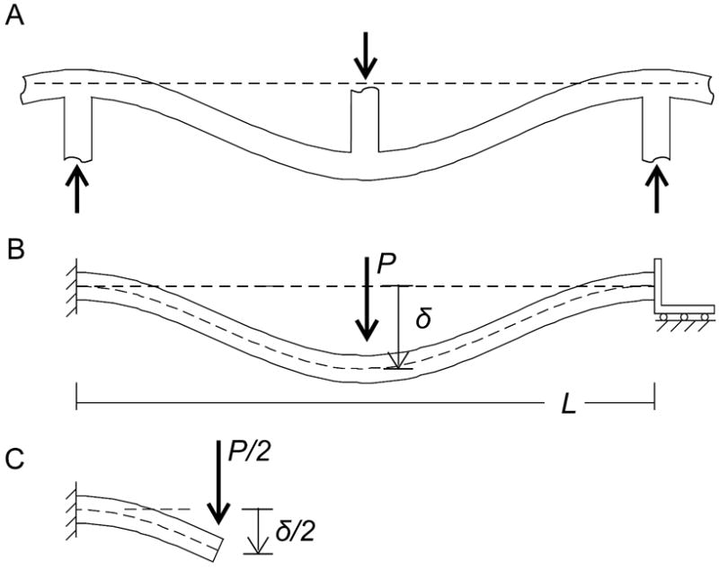
(A) When a load is applied to an RAD16-II gel at the bulk level, the load is thought to be borne at the microstructural level by the bending of filament bundles as they are loaded at their points of intersection. (B) This bending is idealized as a beam whose ends are fastened such that they resist both moments and shear, and whose center is loaded by force P. (C) The problem may be simplified by noting that each quarter of the beam is loaded as a cantilevered beam with a shear load but no moment at the tip.
| (7) |
where δ/2 is the deflection of the tip of the beam due to bending, (P/2) is the applied force, L/4 the length of the cantilevered beam, and I the moment of inertia. For a circular cross section, I = πd4/64, where d is the beam diameter. In an RAD16-II gel, where a typical pore size is L=~300 nm and typical filament bundle diameter d=~30 nm [14], we predict a tip deflection δ/2 = 0.18P, or a deflection of δ = 0.35P at the midpoint, for P in nN and δ in nm. Referring again to the cellular solids model, we note that bulk strain scales as ε ~ δ/L and bulk stress as σ ~ P/L2, giving a bulk Young’s modulus of Eb = σ/ε = P(L/4) 3/IEf. (The subscripts f and b are used to distinguish between filament and bulk properties.) By algebraic manipulation we find
| (8) |
where k is a constant of order 1. This predicts for RAD16-II a Young’s modulus of Eb ~ 1 MPa, an over-estimation based on the experiments by a factor of 100–1000.
Could this discrepancy be due to the mild anisotropy of cohered RAD16-II filaments found in the present study (explanation 1)? Consider that our cantilevered beam may deflect not only in bending but in shear, and that a low shear modulus makes this deflection greater than it would be in an isotropic material. However, deflection due to shear, δshear=(P/2)(L/2)/AG (A is the cross-sectional area, G is the shear modulus of 1.8 GPa), is small, less than 10% of bending deflection even after accounting for anisotropy. The anisotropy of tightly packed filament bundles therefore fails to account for the compliance of RAD16-II gels.
Is the shear load resulting from small bulk strains sufficient to cause slippage between filaments of RAD16-II (explanation 2)? While points of slippage failure may propagate within a filament bundle, the grain boundaries found at junctions between filament bundles would stop the failure propagation. Since the spacing between these junctions is about 300 nm and the diameter of the filaments 30 nm, we take the maximum failure surface to be the area 300 nm × 30 nm = 9000 nm2. Each particle in our coarse-grained model represents an area of 0.48 nm × 6 nm = 2.88 nm2. We can conservatively assume that the number of particles on a failure surface will not exceed 9000/2.88 = 3125. We apply Equation (6) to ask what level of shear stress could cause failure on a surface of this size on ordinary time scales of t ~ 1 s (t* = 8×10¹⁰) and find that a shear load of 45 MPa (ΠP=15) is needed.
Using the cellular solids model outlined above, we estimate that a load of P = 10 nN (or σ = 444 kPa) produces a 10% bulk strain. Under the loading conditions of Figure 10, the average shear across the filament bundle is τave= P/2A = 7 MPa. The maximum shear in a beam with a circular cross section is τmax =1.5τave= 11 MPa. Even under conservative assumptions, then, the shear load is not sufficient to produce slippage in a tightly packed filament bundle.
Consider now explanation (3), that filament bundles are either not monolithic or have weak points due to packing imperfections. We repeat the cellular solids analysis treating each filament bundle not as a single beam but as many independent smaller beams. Each filament has a cross-sectional area of about 12 nm2, corresponding to an effective diameter of about d=4 nm. In a 30-nm bundle, with cross-sectional area 700 nm^2, about n=50 individual filaments exist. Equation (8) becomes
| (9) |
where k is a constant of order 1. Taking Ef to be 15 GPa this gives a bulk Young’s modulus of ~24 kPa, on the order of experimental results, e.g. by Leon et al. [43]. Thus, experimental and theoretical results are consistent if bundled filaments do not transfer significant shear between one another and bend independently rather than as a monolithic beam. This would be expected if the internal structure were random rather than the highly ordered arrangement assumed in the previous analysis. In this scenario, the charged groups interact only loosely, and are therefore free to slide relative to one another. Further investigations of the fiber internal structure will be needed to confirm this hypothesis.
These predictions suggest two potential means for increasing the modulus of AFP gels. One is to enhance the extent to which the filaments align in the idealized fashion with the hydrophilic side groups optimally matched. In this instance, the gel bulk modulus could increase, approaching the 1 MPa prediction from equation (8). While this might seem challenging, there is evidence with a different peptide sequence that fibers can be formed that exhibit ordered structure on a scale of microns, although the geometry of these fibers is more sheet-like than cylindrical [46]. A second, perhaps more feasible approach would be to introduce a cross-linking agent that bridges between filaments internal to the fiber, producing a gel modulus somewhere between the two limiting cases presented above. For this strategy, the cross-linking agent should be much smaller than the previously used streptavidin [27] or transglutaminase [9], to ensure that it accesses the core of the fiber.
5. Conclusions
We have demonstrated that noncovalently bundled filaments may exhibit elastic behavior at low stresses and small displacements, with mild anisotropy. Higher loads may introduce inelastic deformations associated with transitions between minima of free energy. The frequency of inelastic slippage between closely cohered filaments is a stochastic function of shear stress and the size of the loaded surface. Extrapolating simulation results to the time scale of seconds with conservative assumptions, we found that filament bundles are not likely to commonly fail under less than 45 MPa of shear. An approximate analysis based on a cellular solids model shows, however, that tightly adhered filament bundles would experience a maximum shear stress of only about 11 MPa, while the shear stress in bundles with void spaces would be lower still. We conclude that neither filament anisotropy nor slippage between adhered filaments can satisfactorily account for the low bulk Young’s modulus of RAD16-II or other AFP gels. However, if bundled filaments are assumed to be well lubricated (e.g. by included water), the bulk Young’s modulus and the Young’s modulus of RAD16-II filaments are consistent.
Figure 4.
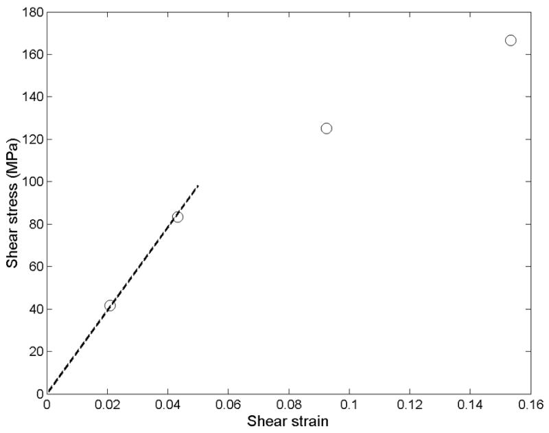
The trajectories in Figure 3 exhibit a linear stress-strain relationship only up to about 5% strain. In this low-strain region, the shear modulus is 1.8 GPa. At larger strains, strain softening occurs.
Acknowledgments
The authors wish to thank Aurore Zyto and Jeenu Kim for many constructive discussions on molecular dynamics, Al Davis and Seung Lee for their continuous help on using computational resources, and Patrick Doyle for his insights on modeling. This material is based upon work supported under a National Science Foundation Graduate Research Fellowship and a research grant from the NIBIB (EB003805). This research was also supported in part by the National Science Foundation through TeraGrid resources provided by SDSC.
Footnotes
Publisher's Disclaimer: This is a PDF file of an unedited manuscript that has been accepted for publication. As a service to our customers we are providing this early version of the manuscript. The manuscript will undergo copyediting, typesetting, and review of the resulting proof before it is published in its final citable form. Please note that during the production process errors may be discovered which could affect the content, and all legal disclaimers that apply to the journal pertain.
* References
- 1.Buehler MJ. Nature designs tough collagen: explaining the nanostructure of collagen fibrils. Proc Natl Acad Sci U S A. 2006;103(33):12285–90. doi: 10.1073/pnas.0603216103. [DOI] [PMC free article] [PubMed] [Google Scholar]
- 2.Kennedy HJ, Crawford AC, Fettiplace R. Force generation by mammalian hair bundles supports a role in cochlear amplification. Nature. 2005;433(7028):880–3. doi: 10.1038/nature03367. [DOI] [PubMed] [Google Scholar]
- 3.Mogilner A, Rubinstein B. The physics of filopodial protrusion. Biophys J. 2005;89(2):782–95. doi: 10.1529/biophysj.104.056515. [DOI] [PMC free article] [PubMed] [Google Scholar]
- 4.Claessens MM, Bathe M, Frey E, Bausch AR. Actin-binding proteins sensitively mediate F-actin bundle stiffness. Nat Mater. 2006;5(9):748–53. doi: 10.1038/nmat1718. [DOI] [PubMed] [Google Scholar]
- 5.Aggeli A, Bell M, Boden N, Keen JN, Knowles PF, McLeish TC, et al. Responsive gels formed by the spontaneous self-assembly of peptides into polymeric beta-sheet tapes. Nature. 1997;386(6622):259–62. doi: 10.1038/386259a0. [DOI] [PubMed] [Google Scholar]
- 6.Kirschner DA, Inouye H, Duffy LK, Sinclair A, Lind M, Selkoe DJ. Synthetic peptide homologous to beta protein from Alzheimer disease forms amyloid-like fibrils in vitro. Proc Natl Acad Sci U S A. 1987;84(19):6953–7. doi: 10.1073/pnas.84.19.6953. [DOI] [PMC free article] [PubMed] [Google Scholar]
- 7.Zhang S, Holmes T, Lockshin C, Rich A. Spontaneous assembly of a self-complementary oligopeptide to form a stable macroscopic membrane. Proc Natl Acad Sci U S A. 1993;90(8):3334–8. doi: 10.1073/pnas.90.8.3334. [DOI] [PMC free article] [PubMed] [Google Scholar]
- 8.Aggeli A, Bell M, Carrick LM, Fishwick CW, Harding R, Mawer PJ, et al. pH as a trigger of peptide beta-sheet self-assembly and reversible switching between nematic and isotropic phases. J Am Chem Soc. 2003;125(32):9619–28. doi: 10.1021/ja021047i. [DOI] [PubMed] [Google Scholar]
- 9.Collier JH, Messersmith PB. Enzymatic modification of self-assembled peptide structures with tissue transglutaminase. Bioconjug Chem. 2003;14(4):748–55. doi: 10.1021/bc034017t. [DOI] [PubMed] [Google Scholar]
- 10.Benzinger TL, Gregory DM, Burkoth TS, Miller-Auer H, Lynn DG, Botto RE, et al. Two-dimensional structure of beta-amyloid(10–35) fibrils. Biochemistry. 2000;39(12):3491–9. doi: 10.1021/bi991527v. [DOI] [PubMed] [Google Scholar]
- 11.Balbach JJ, Petkova AT, Oyler NA, Antzutkin ON, Gordon DJ, Meredith SC, et al. Supramolecular structure in full-length Alzheimer’s beta-amyloid fibrils: evidence for a parallel beta-sheet organization from solid-state nuclear magnetic resonance. Biophys J. 2002;83(2):1205–16. doi: 10.1016/S0006-3495(02)75244-2. [DOI] [PMC free article] [PubMed] [Google Scholar]
- 12.Zhang S. Emerging biological materials through molecular self-assembly. Biotechnol Adv. 2002;20(5–6):321–39. doi: 10.1016/s0734-9750(02)00026-5. [DOI] [PubMed] [Google Scholar]
- 13.Park J, Kahng B, Kamm RD, Hwang W. Atomistic simulation approach to a continuum description of self-assembled beta-sheet filaments. Biophys J. 2006;90(7):2510–24. doi: 10.1529/biophysj.105.074906. [DOI] [PMC free article] [PubMed] [Google Scholar]
- 14.Sieminski AL, Was AS, Kim G, Gong H, Kamm RD. The stiffness of three-dimensional ionic self-assembling peptide gels affects the extent of capillary-like network formation. Cell Biochem Biophys. 2007;49(2):73–83. doi: 10.1007/s12013-007-0046-1. [DOI] [PubMed] [Google Scholar]
- 15.Holmes TC, de Lacalle S, Su X, Liu G, Rich A, Zhang S. Extensive neurite outgrowth and active synapse formation on self-assembling peptide scaffolds. Proc Natl Acad Sci U S A. 2000;97(12):6728–33. doi: 10.1073/pnas.97.12.6728. [DOI] [PMC free article] [PubMed] [Google Scholar]
- 16.Zhang S, Lockshin C, Cook R, Rich A. Unusually stable beta-sheet formation in an ionic self-complementary oligopeptide. Biopolymers. 1994;34(5):663–72. doi: 10.1002/bip.360340508. [DOI] [PubMed] [Google Scholar]
- 17.Caplan MR, Schwartzfarb EM, Zhang S, Kamm RD, Lauffenburger DA. Control of self-assembling oligopeptide matrix formation through systematic variation of amino acid sequence. Biomaterials. 2002;23(1):219–27. doi: 10.1016/s0142-9612(01)00099-0. [DOI] [PubMed] [Google Scholar]
- 18.Hwang W, Zhang S, Kamm RD, Karplus M. Kinetic control of dimer structure formation in amyloid fibrillogenesis. Proc Natl Acad Sci U S A. 2004;101(35):12916–21. doi: 10.1073/pnas.0402634101. [DOI] [PMC free article] [PubMed] [Google Scholar]
- 19.Gordon DJ, Balbach JJ, Tycko R, Meredith SC. Increasing the amphiphilicity of an amyloidogenic peptide changes the beta-sheet structure in the fibrils from antiparallel to parallel. Biophys J. 2004;86(1 Pt 1):428–34. doi: 10.1016/S0006-3495(04)74119-3. [DOI] [PMC free article] [PubMed] [Google Scholar]
- 20.Aggeli A, Nyrkova IA, Bell M, Harding R, Carrick L, McLeish TC, et al. Hierarchical self-assembly of chiral rod-like molecules as a model for peptide beta -sheet tapes, ribbons, fibrils, and fibers. Proc Natl Acad Sci U S A. 2001;98(21):11857–62. doi: 10.1073/pnas.191250198. [DOI] [PMC free article] [PubMed] [Google Scholar]
- 21.Davis ME, Hsieh PC, Takahashi T, Song Q, Zhang S, Kamm RD, et al. Local myocardial insulin-like growth factor 1 (IGF-1) delivery with biotinylated peptide nanofibers improves cell therapy for myocardial infarction. Proc Natl Acad Sci U S A. 2006;103(21):8155–60. doi: 10.1073/pnas.0602877103. [DOI] [PMC free article] [PubMed] [Google Scholar]
- 22.Davis ME, Motion JP, Narmoneva DA, Takahashi T, Hakuno D, Kamm RD, et al. Injectable self-assembling peptide nanofibers create intramyocardial microenvironments for endothelial cells. Circulation. 2005;111(4):442–50. doi: 10.1161/01.CIR.0000153847.47301.80. [DOI] [PMC free article] [PubMed] [Google Scholar]
- 23.Narmoneva DA, Oni O, Sieminski AL, Zhang S, Gertler JP, Kamm RD, et al. Self-assembling short oligopeptides and the promotion of angiogenesis. Biomaterials. 2005;26(23):4837–46. doi: 10.1016/j.biomaterials.2005.01.005. [DOI] [PubMed] [Google Scholar]
- 24.Semino CE, Kasahara J, Hayashi Y, Zhang S. Entrapment of migrating hippocampal neural cells in three-dimensional peptide nanofiber scaffold. Tissue Eng. 2004;10(3–4):643–55. doi: 10.1089/107632704323061997. [DOI] [PubMed] [Google Scholar]
- 25.Kisiday J, Jin M, Kurz B, Hung H, Semino C, Zhang S, et al. Self-assembling peptide hydrogel fosters chondrocyte extracellular matrix production and cell division: implications for cartilage tissue repair. Proc Natl Acad Sci U S A. 2002;99(15):9996–10001. doi: 10.1073/pnas.142309999. [DOI] [PMC free article] [PubMed] [Google Scholar]
- 26.Kisiday JD, Jin M, DiMicco MA, Kurz B, Grodzinsky AJ. Effects of dynamic compressive loading on chondrocyte biosynthesis in self-assembling peptide scaffolds. J Biomech. 2004;37(5):595–604. doi: 10.1016/j.jbiomech.2003.10.005. [DOI] [PubMed] [Google Scholar]
- 27.Kim G. M.S. Thesis. Massachusetts Institute of Technology; 2005. Characterization of a peptide biomaterial used for cell-seeded scaffolds with an analysis of relevant stem cell policy. [Google Scholar]
- 28.Caplan MR, Schwartzfarb EM, Zhang S, Kamm RD, Lauffenburger DA. Effects of systematic variation of amino acid sequence on the mechanical properties of a self-assembling, oligopeptide biomaterial. J Biomater Sci Polym Ed. 2002;13(3):225–36. doi: 10.1163/156856202320176493. [DOI] [PubMed] [Google Scholar]
- 29.Kis A, Csanyi G, Salvetat JP, Lee TN, Couteau E, Kulik AJ, et al. Reinforcement of single-walled carbon nanotube bundles by intertube bridging. Nat Mater. 2004;3(3):153–7. doi: 10.1038/nmat1076. [DOI] [PubMed] [Google Scholar]
- 30.Brooks BR, Bruccoleri RE, Olafson BD, States DJ, Swaminathan S, Karplus M. CHARMM: A program for macromolecular energy, minimization, and dynamics calculations. Journal of Computational Chemistry. 1983;4(2):187–217. [Google Scholar]
- 31.Hoover WG. Canonical dynamics: Equilibrium phase-space distributions. Phys Rev A. 1985;31(3):1695–1697. doi: 10.1103/physreva.31.1695. [DOI] [PubMed] [Google Scholar]
- 32.Im W, Lee MS, Brooks CL., 3rd Generalized born model with a simple smoothing function. J Comput Chem. 2003;24(14):1691–702. doi: 10.1002/jcc.10321. [DOI] [PubMed] [Google Scholar]
- 33.Feig M, Onufriev A, Lee MS, Im W, Case DA, Brooks CL., 3rd Performance comparison of generalized born and Poisson methods in the calculation of electrostatic solvation energies for protein structures. J Comput Chem. 2004;25(2):265–84. doi: 10.1002/jcc.10378. [DOI] [PubMed] [Google Scholar]
- 34.Wong SE, Bernacki K, Jacobson M. Competition between intramolecular hydrogen bonds and solvation in phosphorylated peptides: simulations with explicit and implicit solvent. J Phys Chem B. 2005;109(11):5249–58. doi: 10.1021/jp046333q. [DOI] [PubMed] [Google Scholar]
- 35.Evans E, Berk D, Leung A. Detachment of agglutinin-bonded red blood cells. I. Forces to rupture molecular-point attachments. Biophys J. 1991;59(4):838–48. doi: 10.1016/S0006-3495(91)82296-2. [DOI] [PMC free article] [PubMed] [Google Scholar]
- 36.Evans E, Ritchie K. Dynamic strength of molecular adhesion bonds. Biophys J. 1997;72(4):1541–55. doi: 10.1016/S0006-3495(97)78802-7. [DOI] [PMC free article] [PubMed] [Google Scholar]
- 37.Bathe M, Heussinger C, Claessens MM, Bausch A, Frey E. Cytoskeletal bundle mechanics. Biophys J. 2007 doi: 10.1529/biophysj.107.119743. [DOI] [PMC free article] [PubMed] [Google Scholar]
- 38.Evans E. Probing the relation between force--lifetime--and chemistry in single molecular bonds. Annu Rev Biophys Biomol Struct. 2001;30:105–28. doi: 10.1146/annurev.biophys.30.1.105. [DOI] [PubMed] [Google Scholar]
- 39.Doi M, Edwards SF. The Theory of Polymer Dynamics. New York: Oxford University Press; 1986. [Google Scholar]
- 40.Arkhipov A, Freddolino PL, Imada K, Namba K, Schulten K. Coarse-grained molecular dynamics simulations of a rotating bacterial flagellum. Biophys J. 2006;91(12):4589–97. doi: 10.1529/biophysj.106.093443. [DOI] [PMC free article] [PubMed] [Google Scholar]
- 41.Kis A, Kasas S, Babic B, Kulik AJ, Benoit W, Briggs GA, et al. Nanomechanics of microtubules. Phys Rev Lett. 2002;89(24):248101. doi: 10.1103/PhysRevLett.89.248101. [DOI] [PubMed] [Google Scholar]
- 42.Salvetat J-P, Briggs GAD, Bonard J-M, Bacsa RR, Kulik AJ, Stöckli T, et al. Elastic and Shear Moduli of Single-Walled Carbon Nanotube Ropes. Physical Review Letters. 1999;82(5):944. [Google Scholar]
- 43.Leon EJ, Verma N, Zhang S, Lauffenburger DA, Kamm RD. Mechanical properties of a self-assembling oligopeptide matrix. J Biomater Sci Polym Ed. 1998;9(3):297–312. doi: 10.1163/156856298x00668. [DOI] [PubMed] [Google Scholar]
- 44.Gibson LJ, Ashby Michael F. Cellular Solids: Structure and Properties. Oxford: Pergamon Press; 1988. [Google Scholar]
- 45.Satcher RL, Jr, Dewey CF., Jr Theoretical estimates of mechanical properties of the endothelial cell cytoskeleton. Biophys J. 1996;71(1):109–18. doi: 10.1016/S0006-3495(96)79206-8. [DOI] [PMC free article] [PubMed] [Google Scholar]
- 46.Lu K, Guo L, Mehta AK, Childers WS, Dublin SN, Skanthakumar S, et al. Macroscale assembly of peptide nanotubes. Chem Commun (Camb) 2007;(26):2729–31. doi: 10.1039/b701029j. [DOI] [PubMed] [Google Scholar]


